Revell Type VII Build advice

Collapse
X
 
  • Time
  • Show
Clear All
new posts
  • Avera
    Lieutenant
    • May 2012
    • 95

    #76
    Hi David,

    Going back to the LPB parts or manifolds, in your video (thanks for making it), I see the SNORT system in the sub but only two of the manifolds being used. The stern bulkhead one and the one that sucks in the air. I don't see the one that pumps the air into the tube. Are you using it?

    video link: http://www.youtube.com/watch?v=r27INRGIYhE

    Andrew

    Comment

    • H2Ohaze
      Lieutenant Commander
      • Jul 2011
      • 117

      #77
      Originally posted by He Who Shall Not Be Named

      Let's have a picture of the 'mystery' LPB manifold.

      David
      here is a picture:
      Attached Files

      Comment

      • He Who Shall Not Be Named
        Moderator
        • Aug 2008
        • 12321

        #78
        Originally posted by H2Ohaze
        here is a picture:
        If you have a situation (the 1/144 SEAWOLF is a prim example) where the sail is way forward on the hull and you want to put the sail induction line at the extreme front end of the SD, you use this manifold. It transitions the vertically placed hose that runs up into the sail to a horizontal hose that runs into the middle manifold where it is passed on to the manifold on the outer face of the motor bulkhead. Most people won't need this LPB manifold.

        David
        Who is John Galt?

        Comment

        • Avera
          Lieutenant
          • May 2012
          • 95

          #79
          Hi David,

          Is the stern manifold glue on or just pressed onto the brass tubes coming off the bulkhead?

          In either case both lines run from the stern forward with one going up the sail (induction line) and the other going into the ballast tank (need to drill a hole).

          Now do both of these lines attach to the manifold that has two brass tubes on one side, a single tube on the opposite side and a hole on the bottom where it attaches to the hull?

          Now here is the big question for me and probably relates to the stern manifold, do I have to pull off the two hoses from the stern every time I want to open up the stern dry space? If the stern manifold is pressed on, then the process is simple; just pop off the manifold and remove the stern bulkhead from the Lexan tube. The alternative is a little bit harder as those tube are on tight using a blow dryer to soften the hosing to get it on/off.

          Andrew

          Comment

          • He Who Shall Not Be Named
            Moderator
            • Aug 2008
            • 12321

            #80
            Originally posted by Avera
            Hi David,

            Is the stern manifold glue on or just pressed onto the brass tubes coming off the bulkhead?

            In either case both lines run from the stern forward with one going up the sail (induction line) and the other going into the ballast tank (need to drill a hole).

            Now do both of these lines attach to the manifold that has two brass tubes on one side, a single tube on the opposite side and a hole on the bottom where it attaches to the hull?

            Now here is the big question for me and probably relates to the stern manifold, do I have to pull off the two hoses from the stern every time I want to open up the stern dry space? If the stern manifold is pressed on, then the process is simple; just pop off the manifold and remove the stern bulkhead from the Lexan tube. The alternative is a little bit harder as those tube are on tight using a blow dryer to soften the hosing to get it on/off.

            Andrew
            If you just press-fit the after most manifold in place, it will work, but a bit of water will get into the line -- no big whoop, it's a closed loop and none of it can get into the dry spaces. I glue mine on -- come on! ... how much work is it to slip two flexible hoses on and off their nipples?!! If you do, take care not to get any RTV into the lines!

            You use the brass-tubes-on-one-side-a-single-tube-on-the-opposite-side LPB manifold only if you need to run the induction line well forward. If you do, it becomes an intermediate manifold that dumps discharge air into the ballast tank, but runs the induction hose forward to the specialized LPB manifold previously discussed.

            You can make those flexible hoses a looser fit to the nipples by heating a 3/32" wire slightly and sticking it into the end of the hose. That permanently expands the hose a bit and reduces its hardness.

            You people!

            David

            Click image for larger version

Name:	DSCN0056.jpg
Views:	1
Size:	80.6 KB
ID:	68029Click image for larger version

Name:	DSCN0057.jpg
Views:	1
Size:	84.5 KB
ID:	68030Click image for larger version

Name:	DSCN0059.jpg
Views:	1
Size:	80.7 KB
ID:	68031Click image for larger version

Name:	DSCN0064.jpg
Views:	1
Size:	81.8 KB
ID:	68032Click image for larger version

Name:	DSCN0066.jpg
Views:	1
Size:	85.2 KB
ID:	68033Click image for larger version

Name:	DSCN0068.jpg
Views:	2
Size:	78.5 KB
ID:	68034
            Who is John Galt?

            Comment

            • Reckless
              Lieutenant Commander
              • Jan 2012
              • 183

              #81
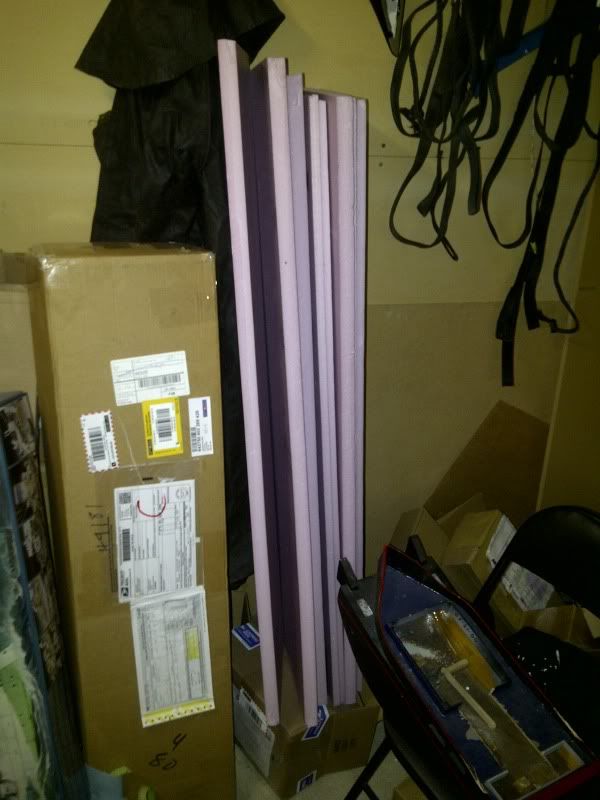
              I got my foam at the local hardware/home improvement place (lowes, home depot...etc) I got a full sheet of 1/2 inch thick and a full sheet of 1 inch thick... I use the 1 inch for working/transport stands, and inside my other boats if needed... and cut carve shave the 1/2 to fit for the sub... pink exterior foam.. I beleive it's ment for under floors, and under siding

              I don't have a truck, I have a 4dr econo family sedan... I asked a nice person in the home depot with a sharp blade to make each sheet 4 pieces for me...

              I think it was $18 cnd with taxes


              Originally posted by Avera
              On a side note regarding the trim foam, any thought on the grey plumbing foam used to insulate pipes? The form comes in a split tube 6 feet long by 4.5 inches wide and about 3/8 inch thick. It appears closed cell (nearly as dense as neoprene but lighter) and does not retain water. Giving its curved shape, it should easily conform to the hull. My LHS does not carry any of the pink foam, nor does the local craft store.

              Andrew

              Comment

              • Avera
                Lieutenant
                • May 2012
                • 95

                #82
                Hi David,

                I was looking at the photos of your VIIC sub SD and noticed that the induction manifold and fill manifold are one unit. The SD came with them as two separate units. I assum this is not a be deal, just requiring the gluing of two parts instead of one and perhaps allowing for better location of either one.

                Comment

                • H2Ohaze
                  Lieutenant Commander
                  • Jul 2011
                  • 117

                  #83
                  Originally posted by Avera
                  Hi David,

                  I was looking at the photos of your VIIC sub SD and noticed that the induction manifold and fill manifold are one unit. The SD came with them as two separate units. I assum this is not a be deal, just requiring the gluing of two parts instead of one and perhaps allowing for better location of either one.


                  Avera, are you sure about that? The pic I posted above shows just a single right angle manifold, but David said that is only for subs such as Seaview with foreward sails. In my SD driver, which must be similar to the one shipped to you, there definitely is a "middle" manifold which accommodates both the induction from the sail AND the return from the pump- dumping into the top of flooded ballast tank.

                  The one change from older "middle" manifolds is that the induction intake tube is parallel, not perpendicular, to the lexan SD tube.

                  Comment

                  • Reckless
                    Lieutenant Commander
                    • Jan 2012
                    • 183

                    #84
                    the top manifold (2 tubes inline with the SD, and 1 tube up for the snort "snorkel") should go between the gas fill, and the tank vent.. this will put it under the sail.

                    I got mine from another user .. with the boat itself 95% built, and the SD assembled... but the snort top manifold was put in the same location as for a GATO (in front of the gas fill) ... and it ends up being right under the front gun... not the sail... so I've had to make minor adjustments and compromises.... the big one being that I had to lift the deck a few mm's (I just stacked magnets) so the snort tube could curl back under the deck and into the sail .

                    oh... and a word of advice..... don't get the wood deck... it's a pain in the rear...

                    Comment

                    • Avera
                      Lieutenant
                      • May 2012
                      • 95

                      #85
                      H2Ohaze,

                      Look at the photos in the Cabal report regarding trimming the VIIC. It shows one combined manifold near the gas tank.

                      Comment

                      • H2Ohaze
                        Lieutenant Commander
                        • Jul 2011
                        • 117

                        #86
                        Originally posted by Reckless
                        the top manifold (2 tubes inline with the SD, and 1 tube up for the snort "snorkel") should go between the gas fill, and the tank vent.. this will put it under the sail.

                        I got mine from another user .. with the boat itself 95% built, and the SD assembled... but the snort top manifold was put in the same location as for a GATO (in front of the gas fill) ... and it ends up being right under the front gun... not the sail... so I've had to make minor adjustments and compromises.... the big one being that I had to lift the deck a few mm's (I just stacked magnets) so the snort tube could curl back under the deck and into the sail .

                        oh... and a word of advice..... don't get the wood deck... it's a pain in the rear...
                        Yes, except that the new manifold doesn't have the induction port sticking up from the SD...it now comes in parallel to the SD lexan tube.

                        Which leads to the other issue: From studying pics that David gave me of his VIIC just converted to SAS (yes at least one does exist at this time), my guess is that the hose for the new float valve is aft of the periscope where the old induction hose was mounted(??).

                        So I just wanted to get a fix on the best place to mount that manifold taking into account: 1) hose now comes in parallel, not perpendicular; 2) The tube that connects down from the deck/sail will move aft of it's current (periscope) location(?), the better to fit the float valve under the sail; 3) The SAS includes a safety valve which is a small canister which I think will have to mount outside of SD and therefore may affect(?) routing of hoses to manifolds.

                        Again, cart before the horse. By the time I am routing the LPB, the SAS may be available, so I just can position everything from deck location of float valve and then mount the manifold, then etc. I'm not worried about it much at the moment.

                        Comment

                        • H2Ohaze
                          Lieutenant Commander
                          • Jul 2011
                          • 117

                          #87
                          Originally posted by Avera
                          H2Ohaze,

                          Look at the photos in the Cabal report regarding trimming the VIIC. It shows one combined manifold near the gas tank.
                          Ummm...yes I know this, that part is obvious. But thank you. Please see my post #86. I guess I could ask you "How near, and also considering future addition of SAS?" :)

                          Comment

                          • He Who Shall Not Be Named
                            Moderator
                            • Aug 2008
                            • 12321

                            #88
                            STOP!!!!

                            You people are making me nuts!

                            Conversion from LPB to SAS for most of our SD's (including the Type-7 SD, discussed here) is a simple matter of adding a snorkel head-valve atop the deck, under the sail; and a safety float-valve within the ballast tank. A slight plumbing change will occur during conversion -- external of the SD's dry spaces. You will install the safety float-valve within the ballast tank, and it will interface with a new forward/intermediate SAS manifold mounted over the ballast tank and a manifold over the forward dry space (from which SD on-board air will be drawn if the snorkel is still underwater when a 'blow' is commanded.


                            So ... why have I taken so long to freeze the conversion arrangement, get product bagged, and into your impatient little mitts?...


                            ... Well, I have completed the arrangement for the 3.5 SD's, That work's out of the way ... whew!. But I'm still working out the last problem with the smaller SD's: where to stick the safety float-valve. Remember, some pictures showed how I initially had the safety float-valve external of the SD? What a nightmare! However, the issue of fit and simplicity has been resolved by putting it in the ballast tank (in some conversions, it will physically replaces the gas on-board bottle), but there remained the problem of a nipple projecting from the bottom of the cylinder -- a source of potential failure should it damaged during handling. I've worked the thing now where the entire safety float-valve is suspended by a screw collar fitting at the top (much as I currently mount the on-board bottles), putting the bottom nipple well within the protective envelop of the ballast tank structure. Once I get the all-thread, taps and dies needed to achieve this thread cut to the neck of the 'new' safety float-valves, we're in business. I've gone through a LOT of copper, boys and girls!

                            Anyway ... that's my story, and I'm sticking to it, damit!


                            David
                            Who is John Galt?

                            Comment

                            • H2Ohaze
                              Lieutenant Commander
                              • Jul 2011
                              • 117

                              #89
                              Thanks, David. Actually, I'm not chomping at the bit for the SAS, I'm still finishing the limber holes, so it will be awhile before I start on the SD plumbing. I was curious how it was going to work, esp as I had been under the impression that the safety valve was going to be placed outside SD, and was trying to envision placement of manifolds and tubing.

                              It sounds like keeping Gas + SAS is problematical, if safety valve will now fit inside ballast space where Gas tank is now. Will run out of room maybe...

                              Comment

                              • He Who Shall Not Be Named
                                Moderator
                                • Aug 2008
                                • 12321

                                #90
                                Originally posted by H2Ohaze
                                Thanks, David. Actually, I'm not chomping at the bit for the SAS, I'm still finishing the limber holes, so it will be awhile before I start on the SD plumbing. I was curious how it was going to work, esp as I had been under the impression that the safety valve was going to be placed outside SD, and was trying to envision placement of manifolds and tubing.

                                It sounds like keeping Gas + SAS is problematical, if safety valve will now fit inside ballast space where Gas tank is now. Will run out of room maybe...
                                Your concern for available real-estate within the ballast tank is a valid one for boats with small ballast tanks like the KILO, SEAWOLF, and Type-7 -- the loss of volume by addition of the safety float-valves volume, plus that of the on-board bottle, would result in a lower than scale waterline in surfaced trim.


                                With some actual run-time under my belt with different boats converted over to SAS only (1/72 SKIPJACK, 1/72 GATO, 1/96 Type-212, 1/72 Type-7 and the Moebius SEAVIEW), I can say with confidence that a gas back-up sub-system is an un-needed luxury. I've found that the SAS is capable of getting the boat up off the bottom (how deep is yet to be determined as I'll need a proper pressure gage to measure maximum pump back-pressure) and high enough out of the water to broach the sub-systems snorkel float to enable complete emptying of the ballast tank.

                                Not to worry, I've abandoned the idea of placing the safety float-valve outside of the SD.

                                Functionality, reliability, accessibility: the watchwords of good, sound mechanical design.

                                I ARE TORPEDOMAN!

                                David
                                Who is John Galt?

                                Comment

                                Working...