
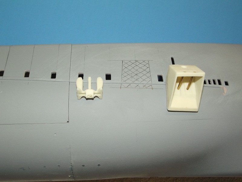
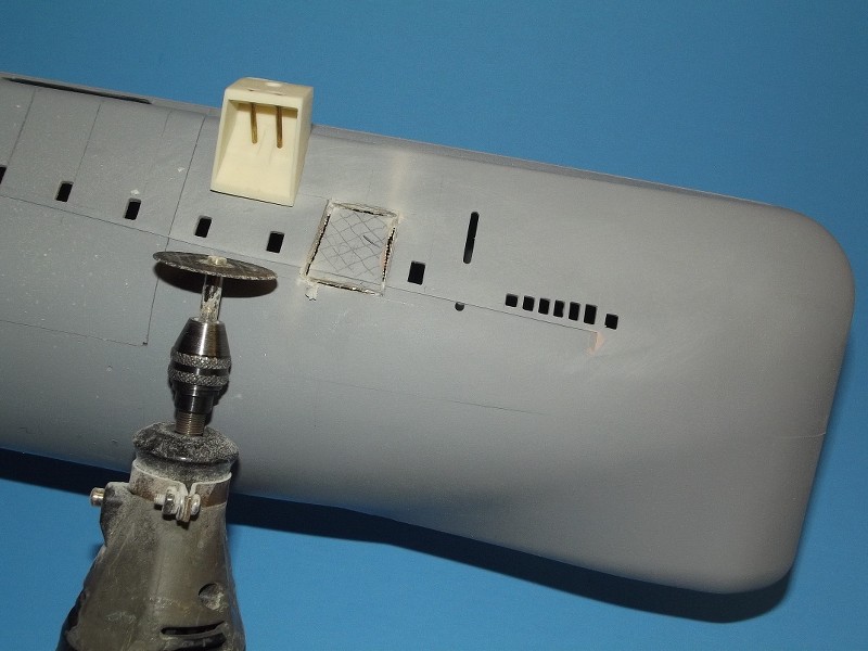
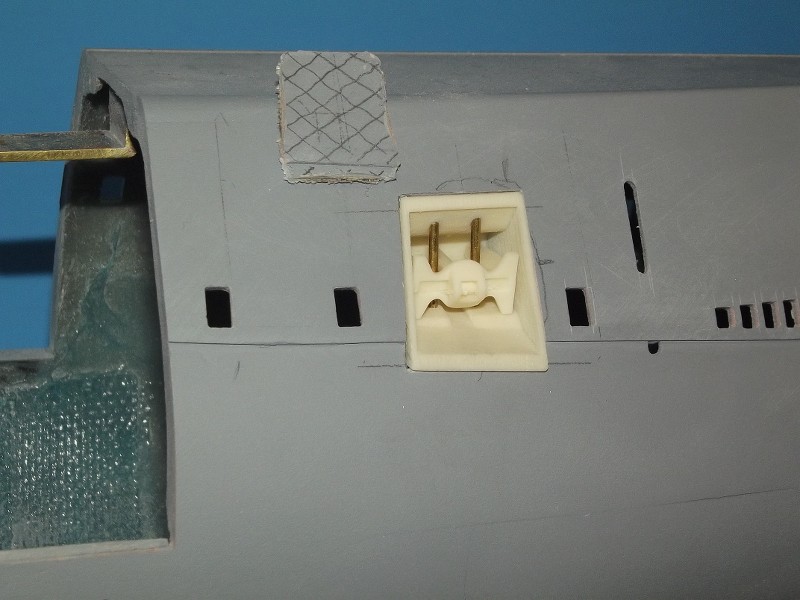
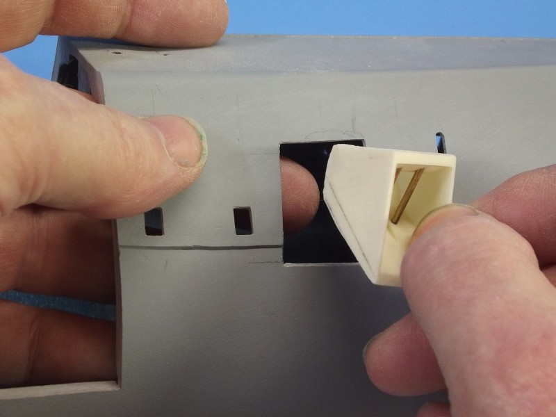
On the ceiling of the control room, I've attached the feed through for the direction finder antennae and the corresponding drive. When the antennae was extended (hydraulics), a clutch cage connected to the feed through and the radio operator cold turn it using the manual drive in the radio cabin.
-
I'm mainly occupied doing sll parts right now. Here's an example including machine telegraph, rpm meter, the steering column of the rudder including a compass daughter, the secondary switchboard, an oxygen meter, lime cartridges, and a vent valve....
On the ceiling of the control room, I've attached the feed through for the direction finder antennae and the corresponding drive. When the antennae was extended (hydraulics), a clutch cage connected to the feed through and the radio operator cold turn it using the manual drive in the radio cabin.
Last edited by DrSchmidt; 12-17-2021, 11:35 AM. -
Are going to display this in 1/2 the hull only or are you going with those red-edged cut out windows?Leave a comment:
-
I'm slowly moving ahead...the pressure hull wall has been painted and weathered. On the left radio room outer wall the switch boxes for echo sounder and gyro compass have found their positions. On the top right the display device for the Atlas echo sounder, left of it the tiny adjustment box for the preamplifier. Left below the pre amplifier and right below it the switch box with the signal generation. The big block at the bottom is the switch box for the Ansch�tz gyro compass and the compass daughters. Cables have to be added....
All that fits quite well in the bottom assembly. The bulkhead to the torpedo room is installed and painted.The table on the back right for the gyro compass has been installed. The big tube in the front is the ventilation duct that sucks air form the radio room, the torpedo room and the battery compartment.
Leave a comment:
-
The radio cabin is glued to the pressure hull and the remaining gaps filled with putty. I put the remaining wirng of the equipment into place an installed the speaking tube (red mouth piece).
The radio cabin speaking tube and the speaking tube for the helmsman rund down from the conning tower through shut off valves (in case of a flodded conning tower).
The whole assembly fits neatly into the bottom structure of the control room...
Leave a comment:
-
Still working on the raio room. All the wall-mounted equipment is glued in place. I also installed the two brass lamps that will be lighted using 1 mm x 0,5 mm LEDs. Installinge the LEDs was a bit of an Odyssee, but now it should work....I hope. Currently I'm putting the cabling in place. Once that is done, I can think about glueing the cabin to the pressure hull wall....
Leave a comment:
-
Continuing work on the radio room. I added equipment on the outer wall....on the left the T3PLL�38 direction finder receiver, next to it the Radione R3 short wave receiver and to the right the fuse panel. Below the desk several power supplies and amplifier boxes. Getting full in there....
Leave a comment:
-
Still working on the raio booth. Added the switch box of the underwater telegraphy...below, under the desk ist the respective filter box. Benarth the radio finder drive I added the respective power supply and the connector box. On the other side wall , beneath the desk, I added the direction box of the GHG with its han wheel.....quite pleased.
Leave a comment:
-
-
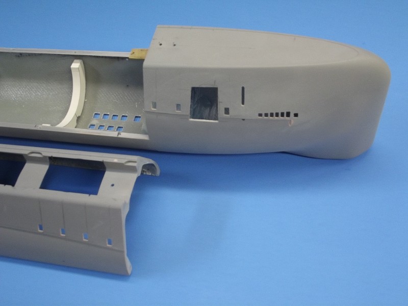
Now seeing these photos again: Did you leave out the anchor well?Leave a comment:
Leave a comment: