
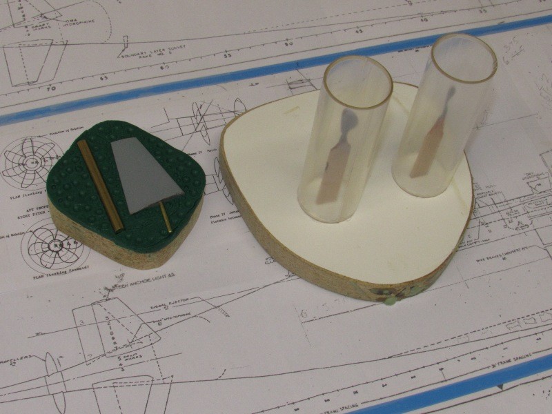
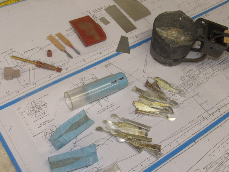
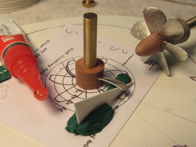
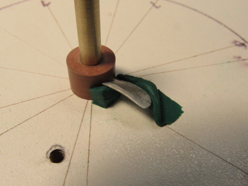
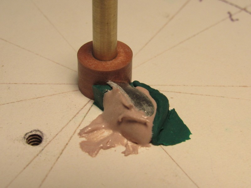
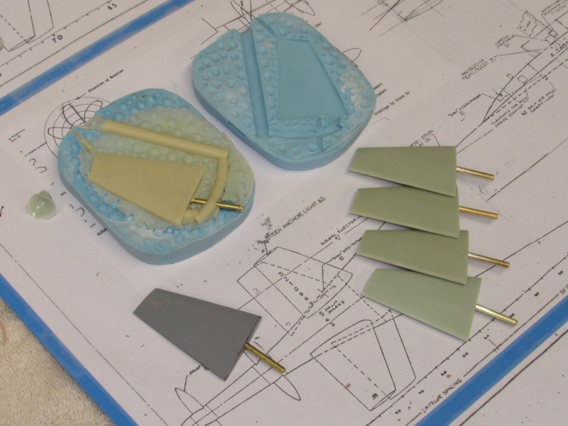
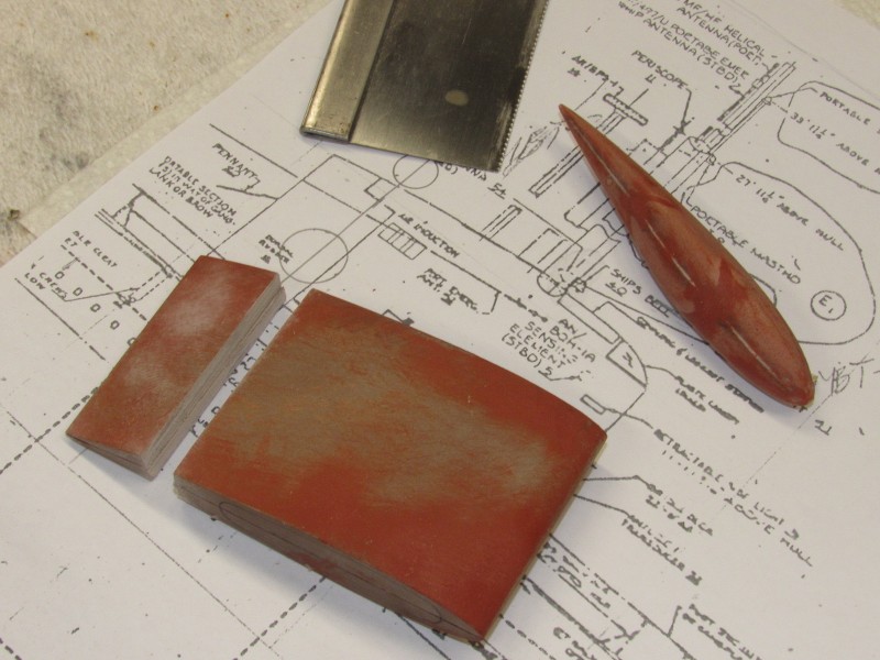
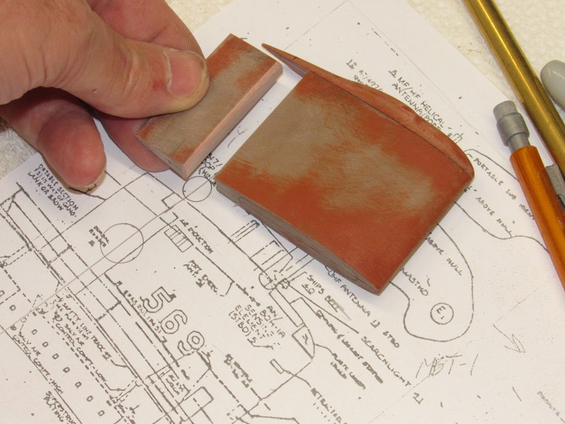
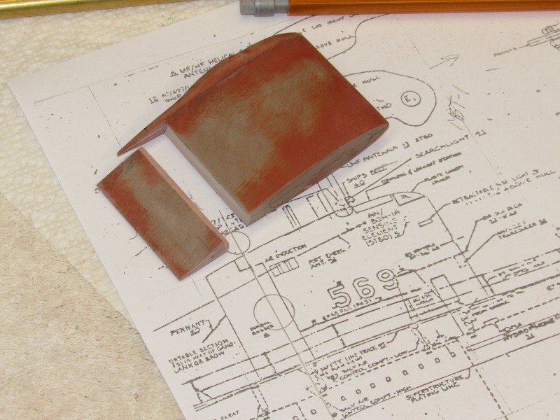
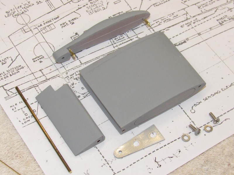
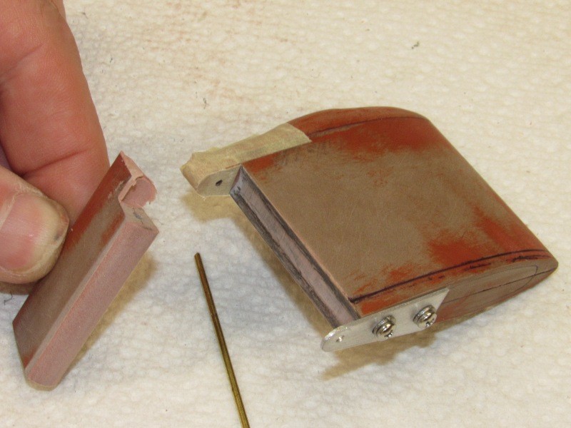
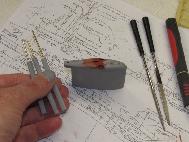
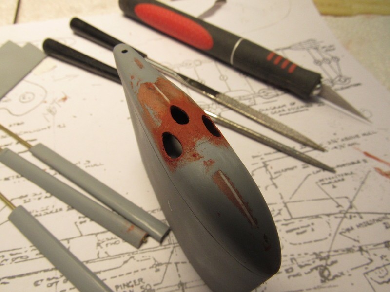
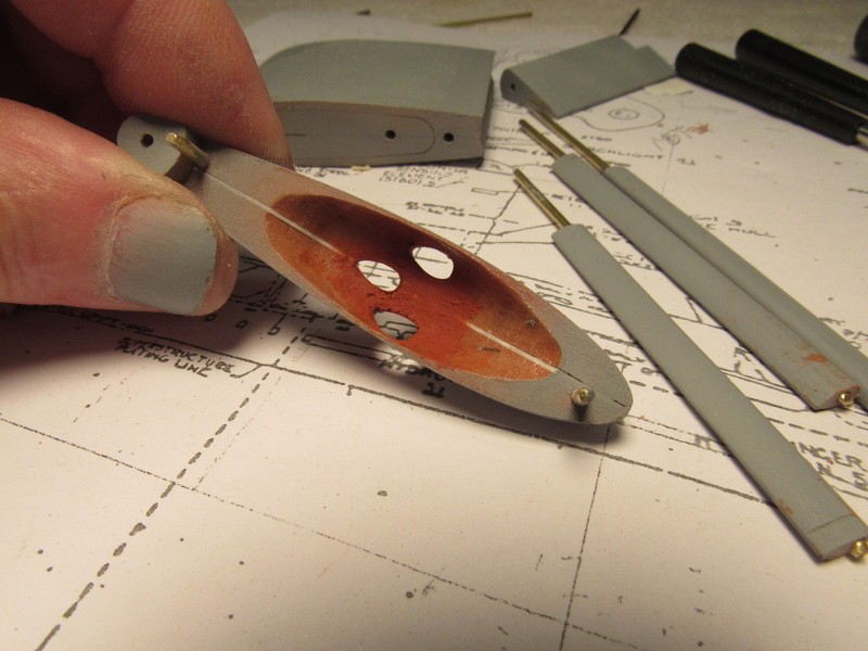
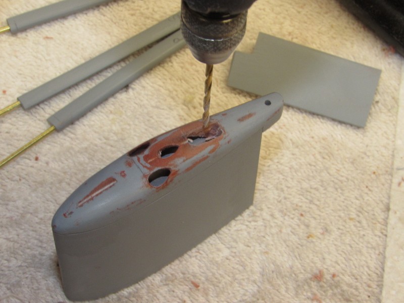
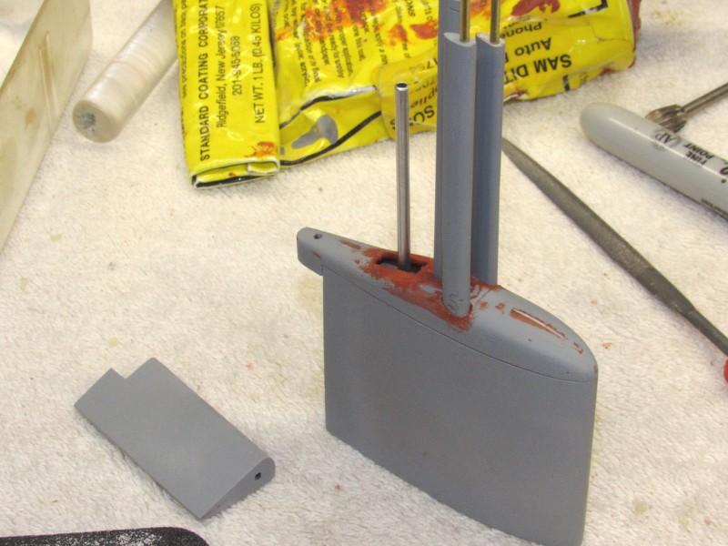
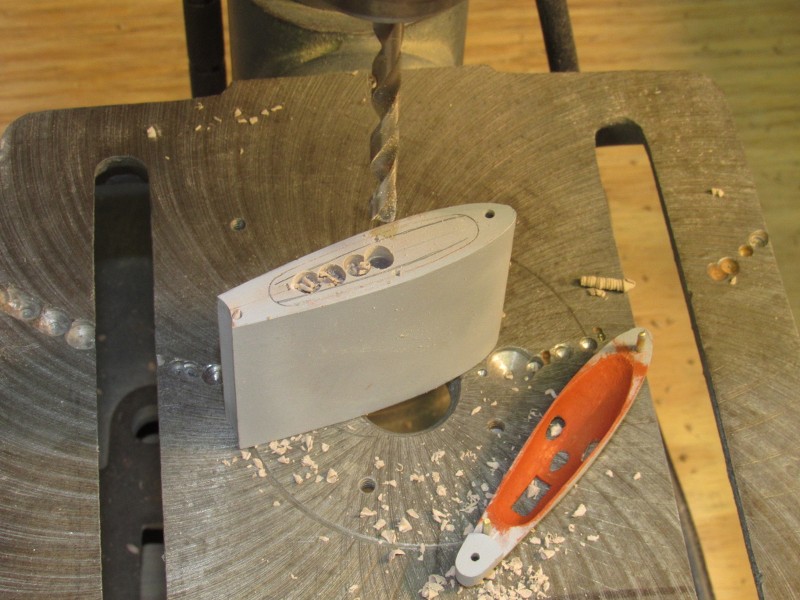
As I need multiple copies of the stern control surface, I made a rubber mold. Same with the two propellers -- each requiring a number of identical blades. The control surfaces will be eventually cast in resin, and the propeller blades cast from white-metal.
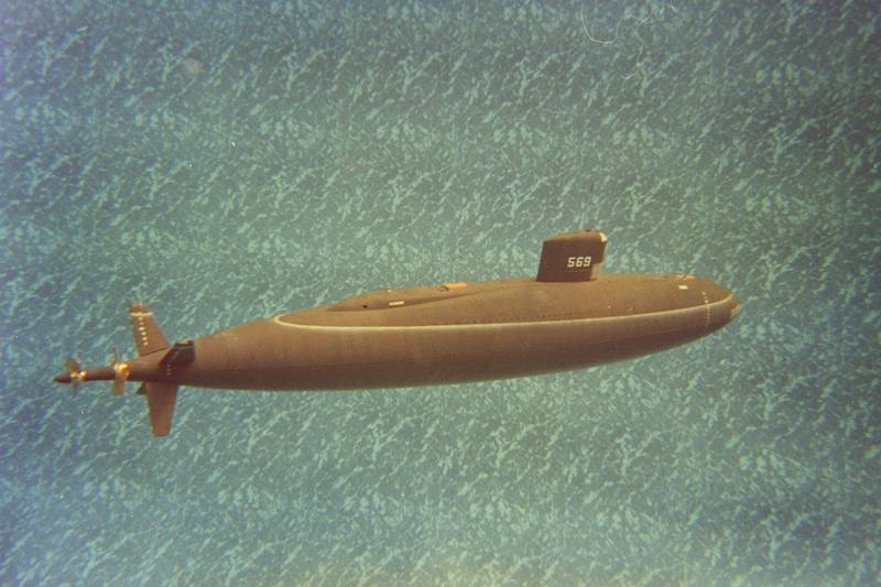
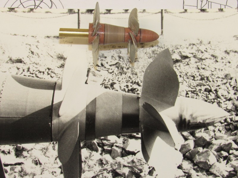
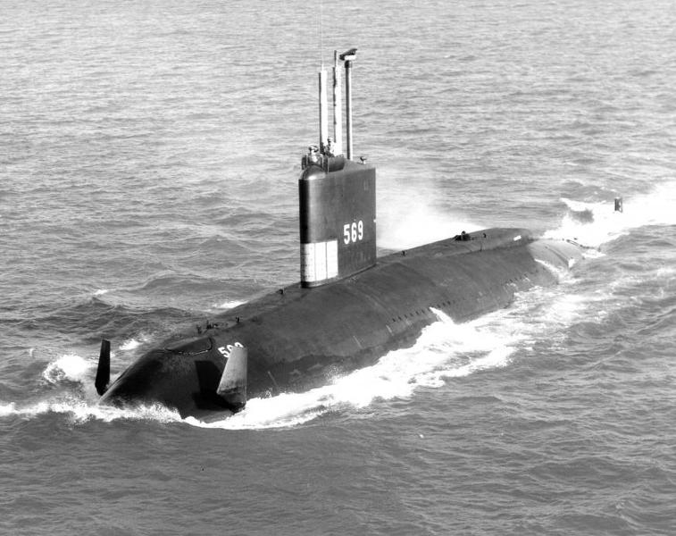
Here's a shot of a 1/60 ALBACORE I did decades ago, to give you an idea how bizarre looking this type running gear is:
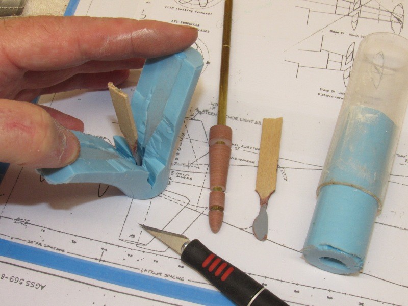
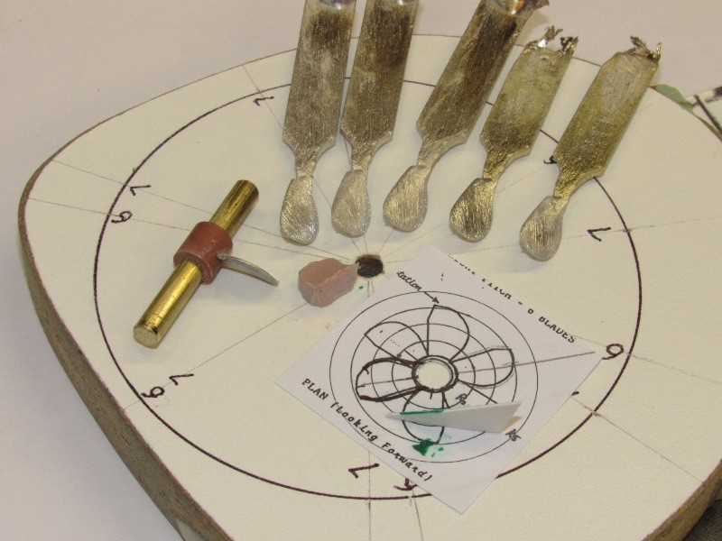
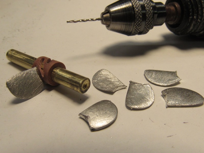
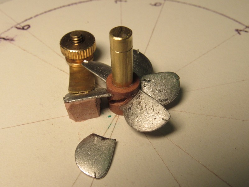
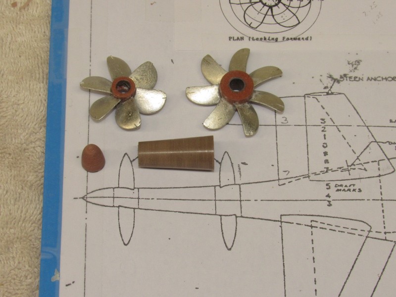
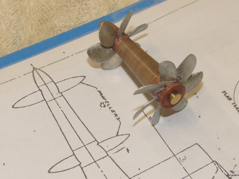
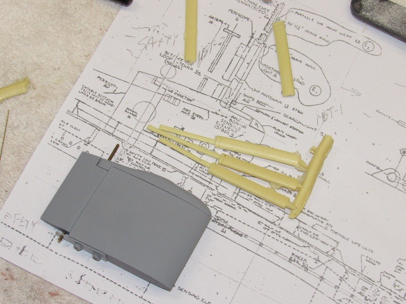
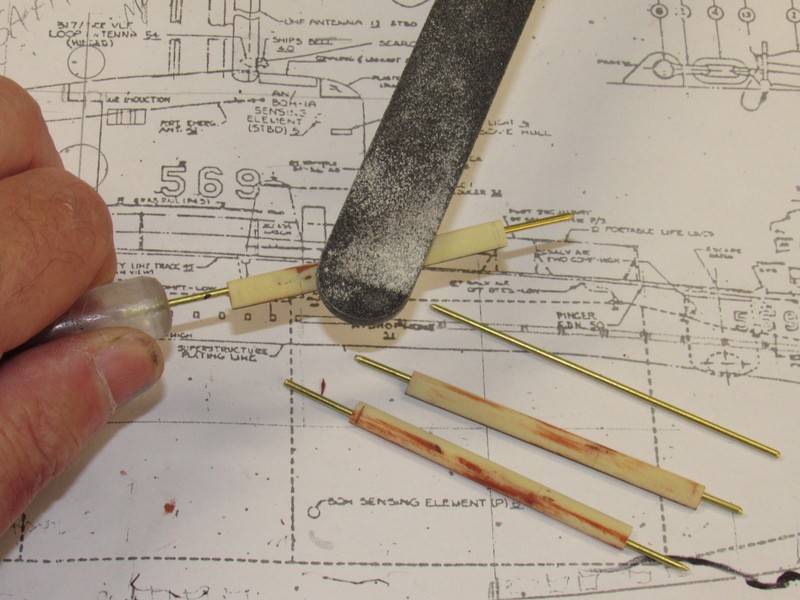
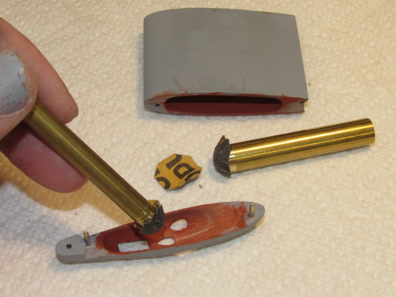
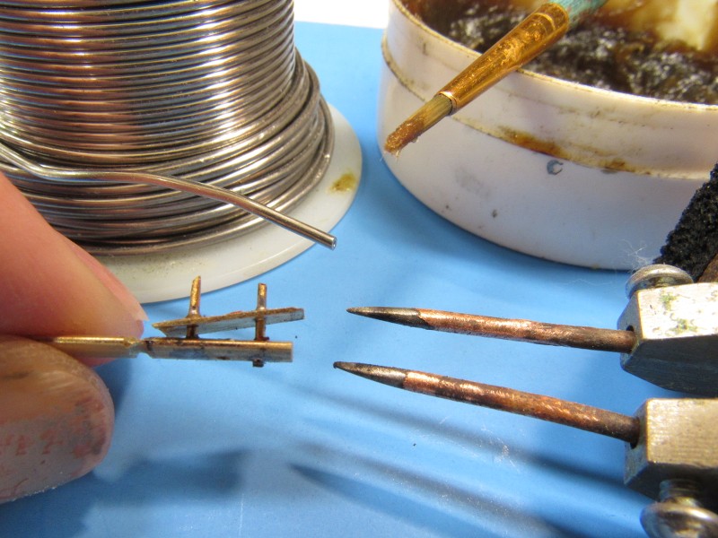
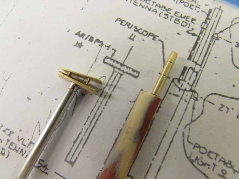
Extracting the propeller masters from the rubber tool that will be used to cast white metal blades -- these assembled around their respective hubs to form production masters.
David
Here's a shot of a 1/60 ALBACORE I did decades ago, to give you an idea how bizarre looking this type running gear is:
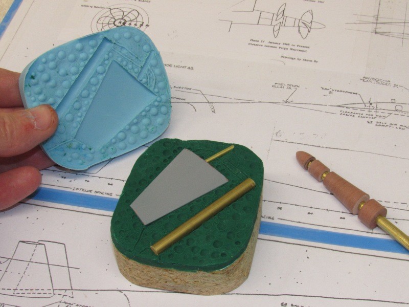
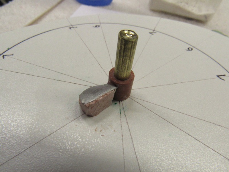
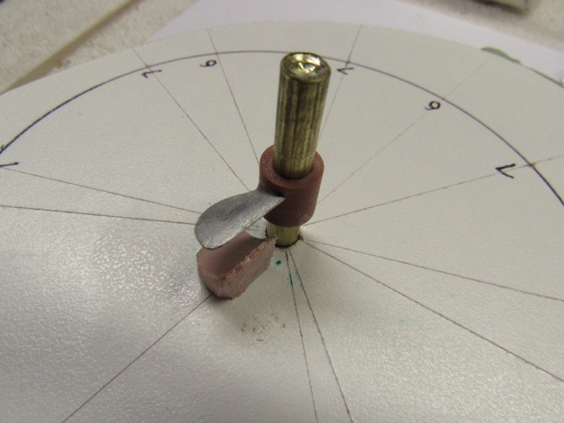
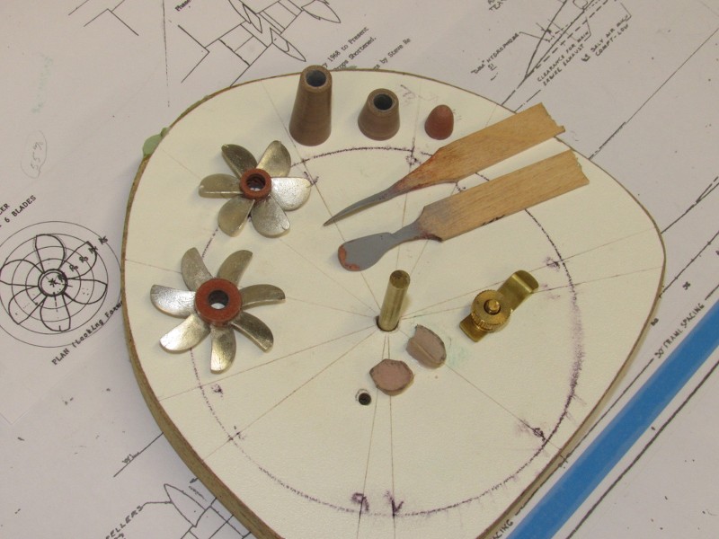
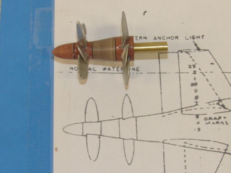
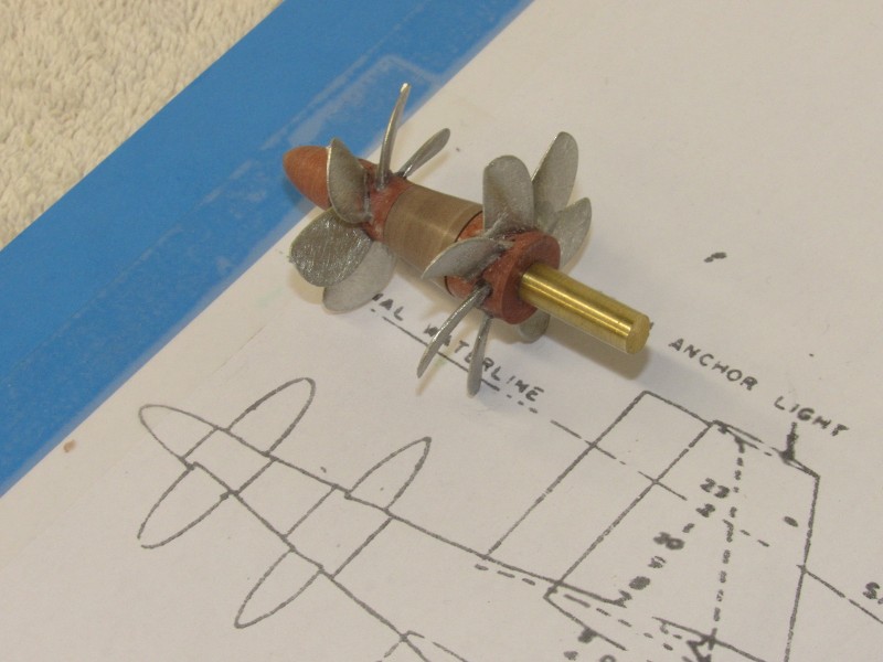
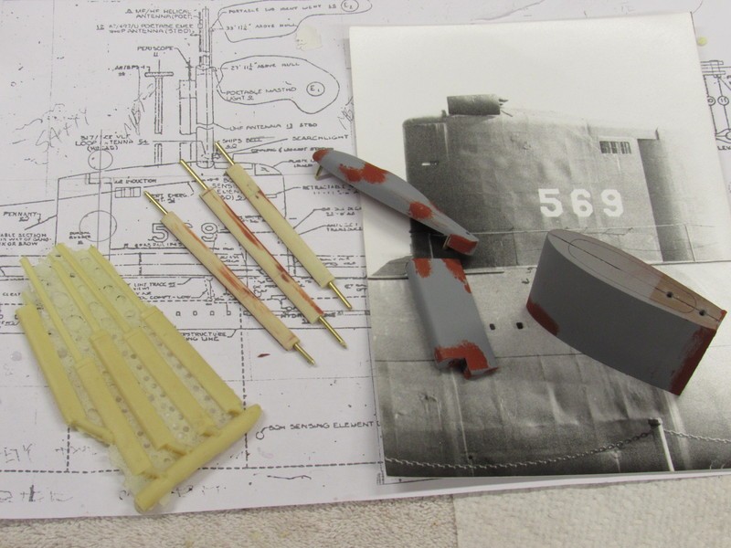
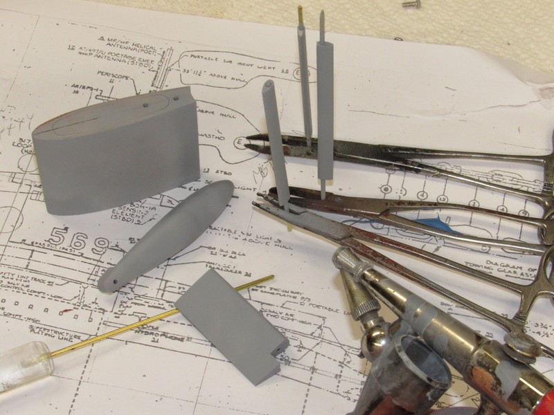
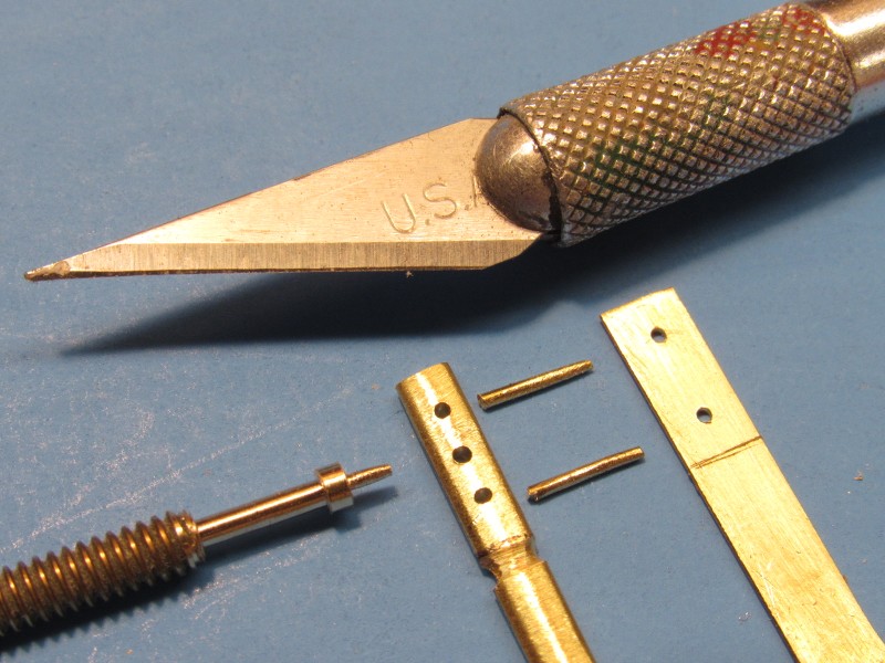
To the right you see RenShape masters for the forward and after propeller hubs and the stand-off piece between them. Illustrated here is the extreme propeller distancing first employed with the counter-rotating, concentric shaft running gear. I've also produced a propeller stand-off master representing the eventual five-foot distancing of the two propellers.
Extracting the propeller masters from the rubber tool that will be used to cast white metal blades -- these assembled around their respective hubs to form production masters.
David


Comment