Scratch build Soviet Project 661 Anchar "Papa" Class SSGN K-222 1/120 Scale.

Collapse
X
 
  • Time
  • Show
Clear All
new posts
  • Davidh
    Captain
    • Nov 2010
    • 719

    #76
    Thanks David and Jorg,

    Jorg, What!, Germany 2-0 loss to Korea. Whats happening!?

    Thanks for the comments guys. I have gone over and had a look at lots of pics of Russian rear ends. (Subs that is) Yep you can see the stern planes are just subtly lower on some boats.

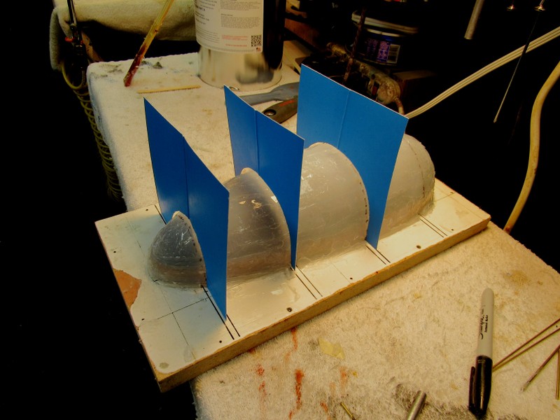
    I am at the stage of development that I have to make a decision to finalise designs. You get to a point where you just have to go ahead and make the decision to proceed with the tooling stage. I reached that a couple of months ago as I started creating the silicon moulds for all the appendage parts. I have spent so much time especially at the stern and I'm now at the point where the design is at a stage I am happy with in regards to the twin boom arrangement. I'm pretty much done here. I will soon be getting the mould boards fabricated and ready to go.

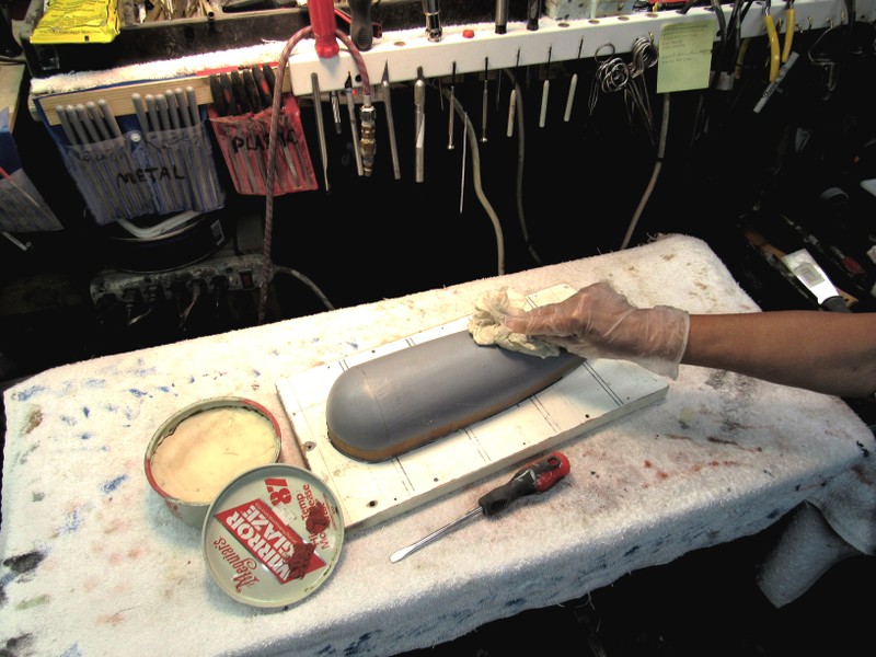
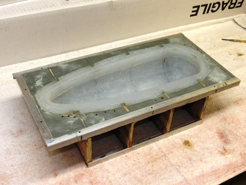
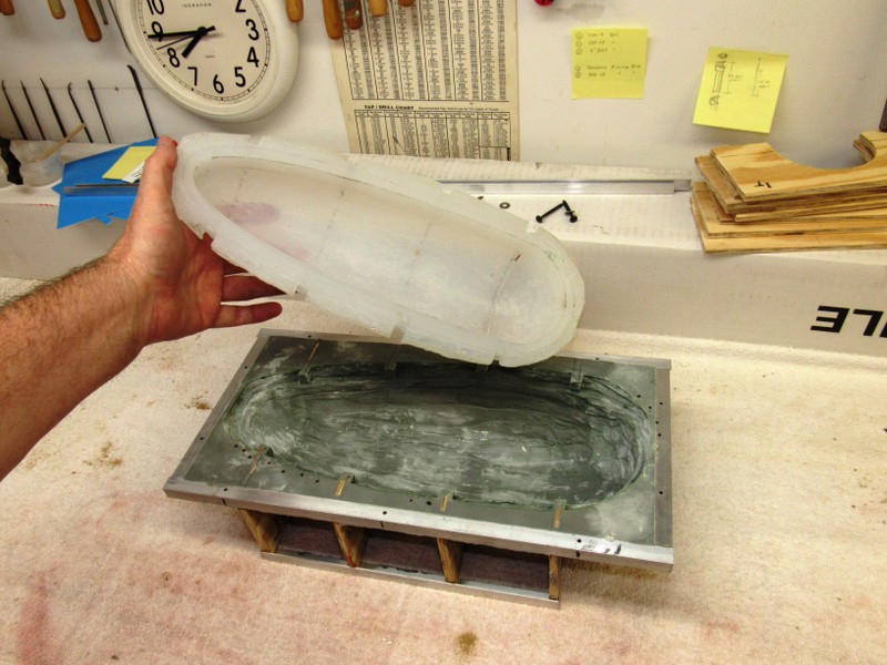
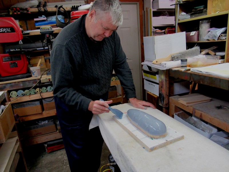
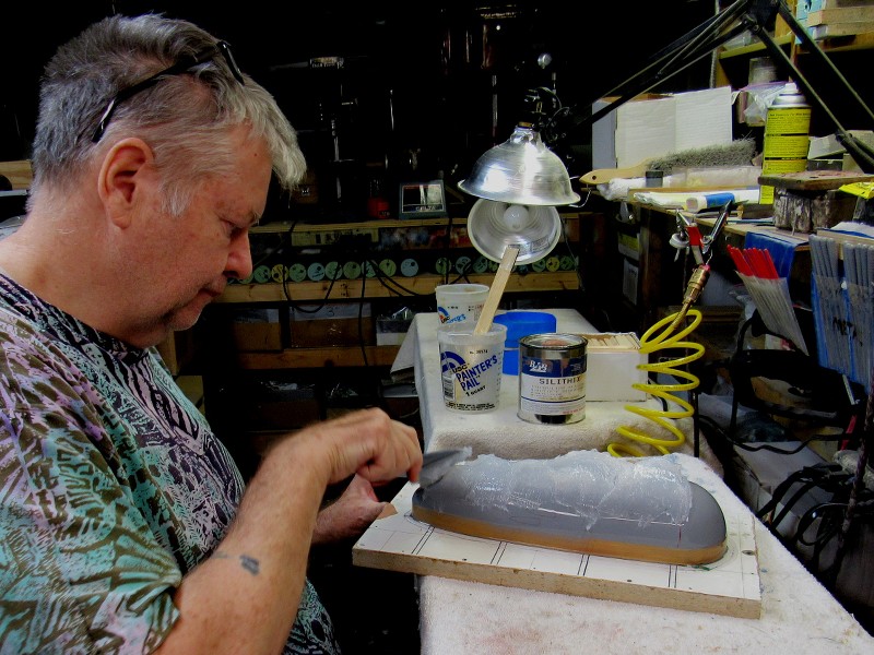
    So I poured the silicon for one side of the sail and waited for it to set. I then pulled that off the base after unscrewing the sides and end boards. This mould came out really well and all I needed now was to brush down a layer of gel coat and then a layer of light weave. The photos below show pretty much the whole process for the other side. Very happy with the result. The silicon recreates every detail.

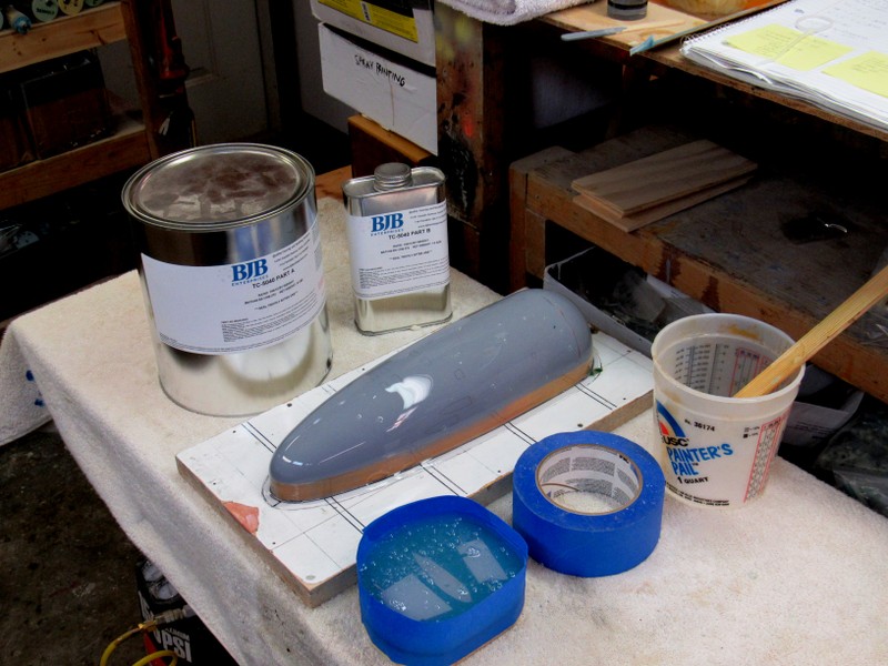
    With every boat that I build I colour code the silicon appendage moulds. Then they all go into a series of boxes for whenever they need to be called upon. This means quick recognition. I didnt have a new pigment colour to work with and the colour I wanted for some reason was really expensive, so I decided to simply mix green, blue and orange that I had from my previous jobs, together to get this nice beige colour.

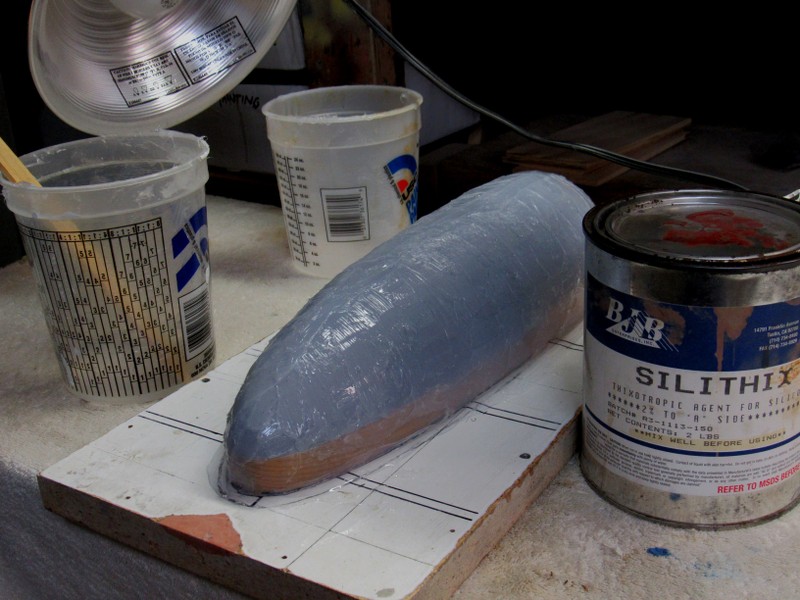
    After completing both moulds, I made the first laid up parts to create the two side parts to make the fin/sail. I will then start on the development of the top of the fin.


    Now it really reminds me of Cheesecake...

    Click image for larger version

Name:	IMG_6428.JPG
Views:	111
Size:	16.5 KB
ID:	126714Click image for larger version

Name:	IMG_6429.JPG
Views:	96
Size:	15.1 KB
ID:	126715Click image for larger version

Name:	IMG_6430.JPG
Views:	99
Size:	17.0 KB
ID:	126716Click image for larger version

Name:	IMG_6435.JPG
Views:	92
Size:	21.3 KB
ID:	126717
    Click image for larger version

Name:	IMG_6437.JPG
Views:	103
Size:	22.9 KB
ID:	126718Click image for larger version

Name:	IMG_6439.JPG
Views:	100
Size:	21.9 KB
ID:	126719
    Click image for larger version

Name:	IMG_6448.JPG
Views:	101
Size:	20.2 KB
ID:	126720

    Comment

    • Davidh
      Captain
      • Nov 2010
      • 719

      #77
      Hello all,

      After creating the molds for the sail and then producing the first sides, I also set up the top of the sail. This is the first time i have moulded a part made from Renshape. Following the same procedures as the sides I poured the silicon into a particle board mold box. Because the top of the fin is very shallow , the mold doesn't need much silicon. They silicon part gets all the detail out of the Renshape master and as a result the glass layup to produce the part also has a fantastic level of detail. Very happy. In the last photo, the middle part is the final layup.

      Click image for larger version

Name:	IMG_6460.JPG
Views:	108
Size:	11.0 KB
ID:	126737Click image for larger version

Name:	IMG_6462.JPG
Views:	103
Size:	11.8 KB
ID:	126738Click image for larger version

Name:	IMG_6482.JPG
Views:	104
Size:	15.2 KB
ID:	126739


      I am at a stage where I am close to finishing up the hull and then proceed to develop the mould box required for the Silicon, Glass and egg crate layup. However before hand I have spent a couple of hours
      just going over the overall hull checking imperfections, sanding and giving tiny amounts of filler where needed. Eyeballing the rear end and making the stern symmetrical. I then spent time just fitting the stern appendages and once more checking for fit and integration. I took time to check alignment of the stern planes and the brass rod fit through either sides of the hull.

      I then spent time filling and sanding the inner flap /middle plane in between the two shafts. I sanded a subtle flat section at either end of the straight section that mounts the flap. This has allowed for the
      swing of the flap up and down ensuring that the edges don't pinch at the move halfway either up or down. I then sanded around the area where this mounts, making sure that the hinged area is square
      relative to the booms as they stick out.

      I worked over the rear hull, going to gradually smoother wet n dry to get the smoothest possible surface before hitting it with several coats of Grey primer.

      Click image for larger version

Name:	papa long 1.jpg
Views:	101
Size:	12.4 KB
ID:	126740Click image for larger version

Name:	IMG_6453.JPG
Views:	90
Size:	13.8 KB
ID:	126741Click image for larger version

Name:	IMG_6449.JPG
Views:	88
Size:	13.3 KB
ID:	126742Click image for larger version

Name:	IMG_6450.JPG
Views:	96
Size:	12.3 KB
ID:	126743


      Click image for larger version

Name:	IMG_2966.JPG
Views:	97
Size:	119.2 KB
ID:	126744Click image for larger version

Name:	IMG_6455.JPG
Views:	101
Size:	22.7 KB
ID:	126745

      Comment

      • Scott T
        Commander
        • May 2009
        • 378

        #78
        This photo from earlier in the post makes it look like the dive plane had straight sides instead of angled sides.
        Last edited by Scott T; 07-10-2018, 12:17 PM.

        Comment

        • JHapprich
          Captain
          • Oct 2017
          • 712

          #79
          One can still cut off the angled edges with a thin blade and glue them to the hull
          Last edited by JHapprich; 07-11-2018, 04:02 PM.

          Comment

          • Davidh
            Captain
            • Nov 2010
            • 719

            #80
            Oh Crap...


            Couldn't you guys point that out to me before I started doing all the moulds. I've only been poring over these pics for the last couple of months. Then again all the drawings show an angled surface intersection with the middle plane / flap. Yes I am about two weeks ahead of what I'm writing.

            After final assembly and checking the fitting of all parts, the overall symmetry of the hull and the twin booms at the back. I then turned towards creating the moulding box form which to create the two hull moulds, top and bottom. This leads into the most tedious and tiring part of the whole exercise. Creating the hull moulds. This is a lot of work and takes up a fair amount of material. My moulding box is simply made out of particle board. Sometimes this is found on the side of the F3 Freeway I drive everyday on the way to work, however this year I have ripped out a kitchen because we are extending the house upstairs and suddenly I have heaps of Cupboard bench tops and large panels to cut up. I measured out two long sides making them about 100mm high and just over a meter long. Two of those followed by two ends about 200 mm wide and 100 high. These would be screwed together with some self tappers and then the top would be cut out. This would be as the sides just over a meter long and 100mm up. I marked a line down the centre of this piece and then place the master over the top. Screwed it down to the top of the basic frame that I had set up.

            Earlier I had cut up some strip particle board, a curve for the front and shorter flat section for the back. These pieces will be screwed down about 10-15mm around the perimeter of the master as it sits in the cutout. They are to limit the distance that the silicon flows and ensure a precise perimeter. I also glue in some small blocks at intervals in order to create registering points along the edge of the silicon mould.

            I then carefully made a rough outline of the overall shape of the master and revised it a couple of times. Then when I was happy with the profile I then drilled some large diameter holes around the edge of the shape.

            Once done I then took out my jigsaw. I don't use this thing very often however when needed it's good and does short work of the profile needing out. As can be seen from the images I did this in sections. I though that the end result produced a reasonably snug fit. Then its simply a case of filing down areas here and there to get an even fit where the model sits level at the equator. Once doen I go over it with the clay and seal the edges and gaps between the board and the sides of the model.
            Click image for larger version

Name:	IMG_6484.JPG
Views:	90
Size:	13.5 KB
ID:	126759Click image for larger version

Name:	IMG_6485.JPG
Views:	88
Size:	13.8 KB
ID:	126760Click image for larger version

Name:	IMG_6488.JPG
Views:	96
Size:	9.7 KB
ID:	126761Click image for larger version

Name:	IMG_6490.JPG
Views:	93
Size:	14.2 KB
ID:	126762


            Click image for larger version

Name:	IMG_6491.JPG
Views:	92
Size:	18.9 KB
ID:	126763Click image for larger version

Name:	IMG_6494.JPG
Views:	91
Size:	14.3 KB
ID:	126764

            Click image for larger version

Name:	IMG_6500.JPG
Views:	94
Size:	12.6 KB
ID:	126765

            Attached Files

            Comment

            • Davidh
              Captain
              • Nov 2010
              • 719

              #81
              Hello all,

              So I had pressed the clay all the way around the equator of the model and then once pressed down took the edge of a ruler, pressed it against the edge of the model and the base and simply screed it along picking up the excess clay and making for a very flat and straight line around the base with a smooth flat surface going right up to the edge of the model.

              I now mixed up a big batch of Silicon resign. I estimated that this top mold would take about a litre and a half of material. One thing is for sure and that you want to be certain that the master is exactly what you want. A major mistake can be expensive. I have taken HWSNBN's advce and have done the pour over several layers over a period of almost a week. I first start off with a layer that is about 5-10mm thick and poured along the base for starters. This filled in the cavity along the sides between the hull and the square strip that surrounds the model. I then made up another batch and added some thixo hardener to thicken up the silicon and then poured over the rest of the master. Making it thicker means that it wont run so easily down the sides. It also means that I can rough up the rop surface even though this is unnecesary for this round as I will be putting on another two layers. The final layer will get the real roughing up.

              This inital layer had to be a reasonable thickness as once again I'm putting my trademark stiffening screen mesh. I have done this for several models including the Borei and also the most recent tooling of the Resolution. I take strip of the very stiff security screen mesh and embed it into the second layer of the mould. The silcon weaves it way through the holes in the mesh and stiffens the siliocn in an area in which you want a flat surface. I have found this ideal for missile decks. HWSNBN is not convinced but i have found it works for me.

              Click image for larger version

Name:	IMG_6515.JPG
Views:	101
Size:	13.6 KB
ID:	126826Click image for larger version

Name:	IMG_6517.JPG
Views:	90
Size:	17.2 KB
ID:	126827Click image for larger version

Name:	IMG_6519.JPG
Views:	96
Size:	14.5 KB
ID:	126828

              First layer had a good amount of catalyst in the mix and so hardened up nice the next day. Once done I then mixed up a new batch of a similar amount and added it to the mould. Evenly pasting it over the master. I didnt add any more along the flange as this had plenty. Now I took the two strips of mesh, bent into an "L" shape using a magna bend from work and pressed them into the corner that runs along the side of the hull as it meets the board. Pressing this mesh down I made sure that the silicon was pushing through the holes in the mesh and mixing through. I then made sure that the rest of the siliocn covbered the mesh and the rest of the hull. I also took a mesh strip and added it over the top of the mould. Once again making sure that the silicon thoroughly covered the mesh and working hard to ensure that there are no airpockets creating cavities under the mesh. You don't want this. You take your time at this stage.

              Click image for larger version

Name:	IMG_6520.JPG
Views:	90
Size:	14.7 KB
ID:	126829Click image for larger version

Name:	IMG_6526.JPG
Views:	89
Size:	16.6 KB
ID:	126830Click image for larger version

Name:	IMG_6527.JPG
Views:	89
Size:	14.5 KB
ID:	126831Click image for larger version

Name:	IMG_6534.JPG
Views:	88
Size:	18.0 KB
ID:	126832Click image for larger version

Name:	IMG_6536.JPG
Views:	91
Size:	11.9 KB
ID:	126833

              24 hours later the second layer with the embedded mesh was in place. It was quite rigid and set solid. Final layer would have thixo added to really thicken it up so I could them make a rough surface for the resin to key into. After the third layer another 24 hours until hard and a great rough surface was produced. I have sometimes found it hard to gauge the thickness of the overall surface. I have had molds come out with thin points that have caused the inner surface to weep a little. That sucks...

              After the third layer has been done I then carefully unscrewed the perimeter form work. Carefully cutting it away so that it doesn't pull the silicon off the mould around the edges as I'm pulling the wood work off.

              Once done you have the outline of the silicon mould. Included are the register cut outs. I added a few more by taking a knife and cutting a 'Vee' shape. I realised that the flange around the back took up alot of silicon I could have gotten away with using less in this area.. Oh well...

              Until next time.

              david h

              Comment

              • He Who Shall Not Be Named
                Moderator
                • Aug 2008
                • 12253

                #82
                This is how I gauge the wall thickness of the rubber glove mold. Templates for specific stations are cut from cardboard. The annular space -- wall thickness of the rubber tool -- defined by the surface of the master and template.


                David
                Who is John Galt?

                Comment

                • Davidh
                  Captain
                  • Nov 2010
                  • 719

                  #83
                  Thanks David.

                  As usual, very good photo's.


                  David H

                  Comment

                  • HardRock
                    Vice Admiral
                    • Mar 2013
                    • 1609

                    #84
                    Go Dave. Onward for the bottom mould.

                    Comment

                    • Davidh
                      Captain
                      • Nov 2010
                      • 719

                      #85
                      Thanks Scott and David,


                      Onward. After having all the silicon cured and the perimeter barriers removed, I laid down a gelcoat of Polyester resin. I mixed up a thick batch and added my customary orange pigment. (All my hulls have an orange hardback after the silicon.) Once this was laid down I have it a fair amount of time to cure. I had to put down a reasonably thick layer in order for it to get into all the crevices and so forth as the last layer of silicon was given a thixo mix to thicken it up and make it really rough so that the hardback would register and be rigidly in place when needed.

                      Now I get on the long road of fiberglass build up. A couple of weeks ago I bought a 4 litre tin of resin. This has saved me a lot of time and effort getting top up litre tins from the local hardware store (Bunnings) which can be a bit overpriced. Soo much better getting it from a wholesaler, even if he is a 40 minute drive away. I started of by using heads of chopped strand. This stuff is thick and because it doesnt need to be detailed ideal for this application where you just want thickness and strength. So layer upon layer over the next couple of days and wanting the temperature to get up to at least 20 degrees. that would be nice.
                      The step where the silicon sits against the side of the hull and met the perimetre would need the fibreglass to curve around a radius. This is something Fibreglass never likes doing. I have a huge bail of fiberglass strange, long strings of the stuff and so I simply cut up several lengths and wrapped it around the base next to the step to build up the level before laying down chopped weave up the side where it doesn't need to conform to such tight bends and curve.

                      I heard on the radio in the workshop how Britain may get up to 37 degrees today and that would be their hottest day on record. What,! we get over 40 degrees a couple of times in December and January. Anyway after a couple of days and lots of layers later It would be time to work out the egg crating. As David shows in all his builds and I have adopted out of common sense is the egg crating that stops a mould , no matter how solid it may be, from warping. I had this unfortunate experience years ago when I did some wing moulds for one of my gliders and it warped really badly. This box would simply be made of 3 ply sheet that was cut down to about 120mm wide and a box would be created out of it.


                      Click image for larger version

Name:	IMG_6538.JPG
Views:	92
Size:	12.4 KB
ID:	126879Click image for larger version

Name:	IMG_6537.JPG
Views:	90
Size:	13.0 KB
ID:	126880Click image for larger version

Name:	IMG_6541.JPG
Views:	89
Size:	11.3 KB
ID:	126881Click image for larger version

Name:	IMG_6544.JPG
Views:	85
Size:	13.8 KB
ID:	126882
                      Click image for larger version

Name:	IMG_6545.JPG
Views:	93
Size:	17.1 KB
ID:	126883Click image for larger version

Name:	IMG_6546.JPG
Views:	100
Size:	11.4 KB
ID:	126884Click image for larger version

Name:	IMG_6551.JPG
Views:	85
Size:	17.5 KB
ID:	126885
                      Click image for larger version

Name:	IMG_6555.JPG
Views:	89
Size:	8.8 KB
ID:	126886

                      The plywood sides need to be high enough to be above the level of the mould. There would be three supports.
                      One at the front, one in the middle and one at the back. These needed to be cut to the approximate profile of the fibreglass layup at that point. Once glued up I layered a couple of extra layers of glass around and inside of the box just to make sure that it had a rigid connection to the base of the mould all over. It is crucial that the egg crate box is firmly holding down the main section of the mould. Its job is to resist warping however it also acts as a really good stand...

                      Any comments or suggestions appreciated..

                      Enough for now...

                      David H


                      Comment

                      • trout
                        Admiral
                        • Jul 2011
                        • 3545

                        #86
                        I have a comment....wow. I appreciate David that you take the time to share your progress.
                        We are getting 45 - 46C (113 - 115F) degree temps this past week and today. Here in Las Vegas, NV we have 2 - 3 months when it is really hot and one of those months when it feels like a few degrees shy of the sun.
                        If you can cut, drill, saw, hit things and swear a lot, you're well on the way to building a working model sub.

                        Comment

                        • Davidh
                          Captain
                          • Nov 2010
                          • 719

                          #87
                          Hello all,

                          So after spending a couple of days laying down layer after layer of fiber glass and waiting for it to dry I made sure that the lower most layer is thick enough. The next step would be the splitting of this top mould off the the particle board splitter board that separates the two halves. The plywood box frame had also hardened during this time and is now quite rigid around the top.

                          After a couple of hours I picked at various parts of the mouild to check that it had dried and hardened all over and then started the process of separating the wooden splitter board from the top half, pulling out the master and making sure that the master did not move inside the top half of the mould. You don't want the master remaining with the wooden board and the pulling away from the top silicon mould. This would not be good.

                          Fiber glass does not stick to the veneer surface found on particle board, so I have never used a release agent with it. Taking a knife and spatula I started running the blade around the outside rim of the fibreglass outer layer. If the glass has hardened up properly , it will start separating in front of the blade as you move along, the change in angle of the material moving up above the blade causing this separation pattern to occur and a colour change as the glass moves away from the backing. Initially I worked my way around the rim, not progressing too far in, gradually working further in deeper and then up against the edge of the silicon mould itself. You need to be careful that the blade doesnt hit any irregularities that might cause a split in the material and delamination happening between layers of resin and glass that make up the flange.

                          Looking under the separated flange I would look to see that the silicon mould was also coming up with it. Prying the siliocn mould away in some places where it was tending to stick to the board required more gentle persuasion. Turning the board over so that the top of the upper mould is resting on the bench I would them push the bottom of the master into the top mould whilst pulling the splitter board away. Boreis separation took a bit of work however Papa's came away quite easily.

                          Once this was achieved I had a look around the flange and where the silicon meets up with the outer flange of Glass. There were some undulations and areas where the original gelcoat had'nt set quite properly. This initially really annoyed me. Leaving it for some time in the sun slowly kicked the curing process along a bit further. I then took a screw driver and spatula and scraped away the residual clay that was originally pressed around the edge to create a seal between the master and the board. Then coats of PVA.
                          Click image for larger version

Name:	IMG_6556 (Large).JPG
Views:	96
Size:	80.2 KB
ID:	127143Click image for larger version

Name:	IMG_6562 (Large) (2).JPG
Views:	90
Size:	67.8 KB
ID:	127144Click image for larger version

Name:	IMG_6564 (Large).JPG
Views:	119
Size:	79.8 KB
ID:	127145

                          Several coats of PVA release agent later, I also decided to run some tape around the joint between the silicon mould and the hardback. This will also make sure that no resin from the bottom mould will seep in between the silicon and hardback of the top mould. It is a bit dissapointing that I had to do this. All my other molds have been so tight I have not needed to do this before. Should probably help with part separation between the two halves. The top and bottom will never need to mate and be tight when producing a hull mould, a precisely flat surface in the flange is not absolutely necessary. Its the rim of silicon that needs to be dead flat as this will be the edge of the top hull half. I did a few more layers of PVA over the flange and the master. Once this was done I could lay up the first Gel coat of the bottom mould hardback. Then once again repeat the process, just without silicon..

                          Click image for larger version

Name:	IMG_6570 (Large).JPG
Views:	100
Size:	94.1 KB
ID:	127146

                          Click image for larger version

Name:	IMG_6571 (Large).JPG
Views:	112
Size:	57.5 KB
ID:	127147
                          Click image for larger version

Name:	IMG_6574 (Large).JPG
Views:	154
Size:	87.9 KB
ID:	127148


                          Yay! I found a reliable way of getting bigger pictures!

                          Enough for now.


                          David H

                          Comment

                          • Davidh
                            Captain
                            • Nov 2010
                            • 719

                            #88
                            Hello,


                            After spending a couple of days laying up several layers of glass roving and being over it. It was time to build the plywood frame for the bottom hull mould. Once again I cut the frames so that
                            they would match with the overall shape of the layout. A curve at the bottom that would fit along the width of the hull and be flat at the top to meet the sides. The egg crates are really good as they
                            double up as a really sturdy support when you are laying up a hull mould.

                            Once this was done it was the usual waiting till all the layers had fully dried and then working out how to pry the two halves apart. This would also be the point at which you saw whether almost two weeks worth of work has been worthwhile or If you will end up frustrated that something early on ruined or nearly ruined the surfaces in both the Silicon and hard shell bottom mould. Fingers crossed.

                            Click image for larger version

Name:	IMG_6575 (Large).JPG
Views:	100
Size:	81.2 KB
ID:	127195
                            Click image for larger version

Name:	IMG_6577 (Large).JPG
Views:	86
Size:	80.4 KB
ID:	127197
                            Click image for larger version

Name:	IMG_6576 (Large).JPG
Views:	155
Size:	83.5 KB
ID:	127196


                            As you can see from the pics, the rim (flange) on the bottom half is narrower then the top half. this is primarily due to the extra width needed to accomodate the
                            silicon mould of the top half mould. Having the purple masking off tape would certainly make separation of the two halves alot easier.

                            Once this was all ready I one again got a spatula of sorts and carefully found the separation between the two halves. Prying the blade along and being careful that it was not catching on an
                            uneven section of glass and riding upward and away from the separation plane was important. Once I made a separation all the way around I could them work my way in with a soft plastic "chisel' of sorts something that could be used for prying but would not scratch the surface. Sometimes I find it hard to predict which mould will separate the most easily , leaving the master in the other mould. After some vigorous moving and prying the top half ended up separating the most easily. I spent a bit of time inspecting the top surface. The Silicon had done and incredible job. The Surface detail was brilliant and there were virtually no air bubbles that can be caused at the beginning if you put too thick a layer of initial silicon down. (I don't have a Vacuum chamber and pump yet) to evacuate all the air before pasteing up the silicon on my moulds so I have to put down a thin layer for starters. It worked! The Sides are nice and straight, I believe the result of embedding a rigid "L'" shape of rigid wire mesh into the silicon. I alos did the same along the top of the mould so the silicon is dead straight along the upper surface of the hull. I also don not have any weak points in the silicon. This is something that had been a problem on earlier moulds. This mould is solid. It is really thick and I love it.


                            Click image for larger version

Name:	IMG_6581 (Large).JPG
Views:	155
Size:	74.9 KB
ID:	127198Click image for larger version

Name:	IMG_6580 (Large).JPG
Views:	93
Size:	52.2 KB
ID:	127199


                            That left the bottom mould holding onto the master. This would require more prying and some frustration. However after a little while the master pulled from the mould. This is where sectional glued master front and back ends can come back to bite. As I was prying out the back end it started giving way but the front section stayed and the hull parted along one of the sections joins just before the PVC pipe breaking that Papa master in two! Oops.... Nice clean break at least!

                            Click image for larger version

Name:	IMG_6582 (Large).JPG
Views:	82
Size:	85.7 KB
ID:	127200


                            Click image for larger version

Name:	IMG_6584.JPG
Views:	92
Size:	13.6 KB
ID:	127201Click image for larger version

Name:	IMG_6583 (Large).JPG
Views:	84
Size:	76.0 KB
ID:	127202

                            Clean out the Residual PVA , peel off the tape and sand back the flange, spray a couple of layers of PVA back on and star the first layup!

                            Enough for now,

                            David H


                            Comment

                            • Davidh
                              Captain
                              • Nov 2010
                              • 719

                              #89
                              Hello all,

                              So I spent some time cleaning out the hull mould and washing off the PVA residue. Then I sprayed in a couple of layers of PVA onto the bottom hull. I l also washed out the top hull silicon mould and dried it, ready for a couple of very fine spray coats of PVA on the silicon. Once this was done and dry I mixed up a batch of gelcoat and moxed some grey pigment into it. Gelcoat is great because it'sn not too thick to not fill crevices but thick enough to generally cling to sides and hold with a nice consistent thickness.

                              Drying to a tacky consistency then allowed me to lay up the first layer of Glass. I try and use the 6 oz cloth as its light and will generally work its way around gentle corners well. Allow that layer to harden then allows me to go over the surface and sand back any tiny or large bumps and spikes where a bit of glass weave for some reason may be sticking up. This will cause a nightmare for laying down the next layer and getting a really big air pocket underneath. After checking the surface and making sure its smooth I wet up the surface and then put on a thicker chopped strand layer. This roving layer is quite thick so you need to really wet it up good. As you work your way around the rim I sometimes find that the material will work its way down the sides, so sometimes I will add strips of finer weave around the rim just the thicken it up enough so that when I sand it later I can get a really neat and consistent edge.

                              I do this with both hulls the silicon mould and the hardback. After a couple of days these two hull halves are ready to pull.


                              Click image for larger version

Name:	IMG_6585 (Large) (2).JPG
Views:	89
Size:	79.1 KB
ID:	127332

                              Click image for larger version

Name:	IMG_6586 (Large).JPG
Views:	86
Size:	82.4 KB
ID:	127333

                              Click image for larger version

Name:	IMG_6651 (Large).JPG
Views:	84
Size:	83.1 KB
ID:	127334


                              Click image for larger version

Name:	IMG_6654 (Large).JPG
Views:	144
Size:	65.8 KB
ID:	127335


                              Finally the moment of truth. Pulling the hull halves out of the moulds. A couple of weeks of work and the first hull parts have finally been made. The silicon mold by nature just peels away beautifully, revelaing superb detail. There was some slight undulations but overall straight and true. I am convinced that the embedded mesh plays a part in this. The sides are straight and the top deck of the mould is also true. Of this I'm really happy. There is also no air pockets nor tiny balls of resin where the resin has found a air bubble pocket in the silicon. None whatsoever! The surface is also very consistent. I had been having a problem a couple of months ago where there was surface crazing on the resin where it must have separated from the silicon or there was some kind of movement just before hardening that was driving me up the wall.

                              The lower hull took a little more convincing. This is because I'm pulling it from a rigid hardback. I usually start at the back end as there is less material to have to dig under. I usually cut plastic strips made from
                              cut strips of plastic 2 litre muilk bottles. Push them under the rear and push and push until it comes up the other side. Pull back and forth as you work your way along the hull until you feel the rest of the hull forward of where you are start pulling away and before you know it, it has popped out.

                              I am really happy with how these two parts have come out. I then take my dremel tool and cut away the excess mess that sticks out above the rim generally bring down the surface to roughly flat and definitely less sharp and rough.


                              Click image for larger version

Name:	IMG_6650 (Large).JPG
Views:	90
Size:	92.3 KB
ID:	127336

                              Click image for larger version

Name:	IMG_6656 (Large).JPG
Views:	90
Size:	81.2 KB
ID:	127337
                              As you can see the surface detail is reasonable. Subtle undulations, and some rough patches the bane of my modelling existence are evident and I has some areas where the gel coat had let me down somewhat. I thought it was thick enough. Once roughly cut out with the Dremel it is a date with the big broad and long sanding board that will bring the equator down to nice and straight. This last photo shows the alignment of the stern top and bottom sections with the twin booms evident. These two hull parts are very close and will make the set up and fitting out of all the control surfaces a lot easier...

                              Then almost all the hull work is fine filling and sanding....

                              Stay tuned......


                              David H

                              Comment

                              • Davidh
                                Captain
                                • Nov 2010
                                • 719

                                #90
                                Hello all,

                                After a busy week in which I went bush then found out by Friday that we have a new Prime minister. Hardly know anything about this new Bloke, Scott Morrison.

                                Anyway,.....

                                Working through the finer points of getting the hulls nice and even and filling and sanding the odd undulation. I then found myself at a point where I could look at the fitting of the stern appendages and how they would go together. A couple of weeks earlier I has cast the stern horizontal planes and then vertical top and bottom rudder sections. I had yet to create a mould for the inner flap ( the horizontal stern plane that sits between the booms.) I have cast a couple of rounds and they work out quite well. It was simply a case of fine sanding and the usual adjustment to get them all working the way they should.
                                Click image for larger version  Name:	IMG_6658 (Large).JPG Views:	1 Size:	513.4 KB ID:	127409
                                Click image for larger version  Name:	IMG_6660 (Large).JPG Views:	1 Size:	118.7 KB ID:	127410
                                Click image for larger version  Name:	IMG_6661 (Large).JPG Views:	1 Size:	94.2 KB ID:	127411


                                A part of this involved cutting out and filing the square holes that allow the support for the urethane stock to fit inside the edge of the hull and allow a little more support for the appendage to grip onto the hull where required. I also had to drill and sand the hole for the rotating shaft of the movable surface. I then had to spend a considerable amount of time ensuring alignment and that the bras rods and absolutely aligned and horizontal ,or vertical for the rudders.

                                In the case of the vertical rudders, the holes marked for the shaft needed to align dead vertically for the top and bottom and at the same time having the hull top and bottom align and sit perfectly atop one another. After drilling the holes in the registered positions I then moved the top hull over the bottom and lowered a brass shaft through both hole. Then carefully slide the top hull incrementally around over the bottom hull and watching how the brass rod gyrates. (Not much, a degree here or there.)
                                Click image for larger version  Name:	IMG_6664 (Large).JPG Views:	1 Size:	95.7 KB ID:	127412


                                Click image for larger version  Name:	IMG_6666 (Large).JPG Views:	1 Size:	96.0 KB ID:	127414


                                Click image for larger version  Name:	IMG_6668 (Large).JPG Views:	1 Size:	81.6 KB ID:	127413


                                Once I had this alignment done to my satisfaction I then started using a round file to remove the material in the twin booms where the twin brass prop shafts would be laid.
                                I then needed to carefully remove a little more material to make sure that the shafts sit level and true with the edge of the lower hull.


                                David
                                Last edited by Davidh; 08-24-2018, 06:15 AM.

                                Comment

                                Working...