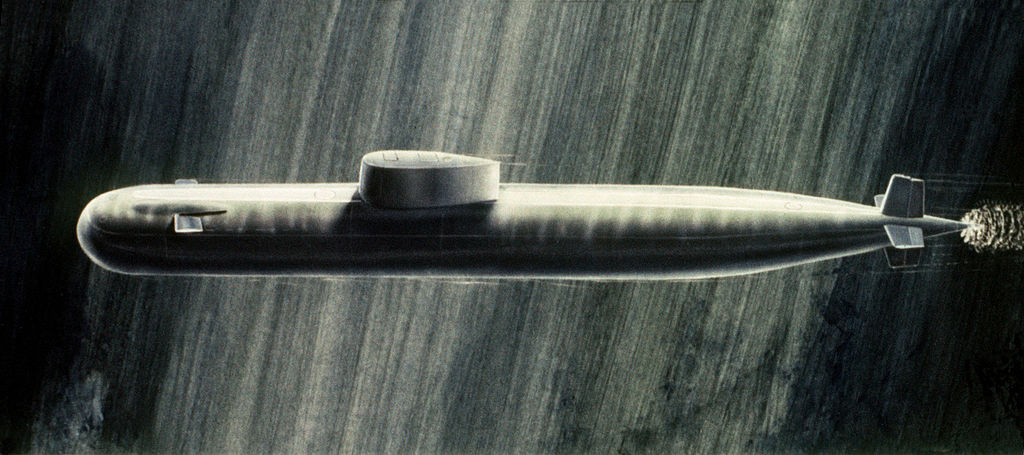
Scratch build Soviet Project 661 Anchar "Papa" Class SSGN K-222 1/120 Scale.

Collapse
X
 
  • Time
  • Show
Clear All
new posts
  • Davidh
    Captain
    • Nov 2010
    • 719

    #61
    It seems like not too long ago I wrote one of these for one of my hero’s. This has come too soon.

    farewel Alan Lavern Bean- Apollo 12, Skylab 3.

    Also a fantastic artist.


    Comment

    • trout
      Admiral
      • Jul 2011
      • 3545

      #62
      yeah, unfortunately many of the space frontiersmen that I grew up watching are aging and succumbing to the final frontier. Whether I am in denial or not, they seem too young to be passing away. I used to record some of the Apollo mission launches on a tape recorder. Loved the sound of the engine roar. I barely remember the Mercury mission, but each revision (Mercury, Gemini, Apollo) brought new excitement and dreams and models to build. I had the Gemini model that had optional landing skids on it (a thought of alternate landing,inspired probably by the Russian landings, other than splashing in the ocean).
      If you can cut, drill, saw, hit things and swear a lot, you're well on the way to building a working model sub.

      Comment

      • The Boattrainman
        Commander
        • Mar 2016
        • 443

        #63
        We're losing touch with the Apollo missions as the pioneers pass away, man's greatest acheivement in my view, we've been going backwards ever since, and at the rate we are killing the planet (pollution, over population, climate change, decrease in bio-diversity etc.etc.), it looks increasing like the moon will have been our only excusion to another world. The whole Mars idea is not a runner at the moment, and time is not on our side...........!

        Rob
        ''We're after men, and I wish to God I was with them........!''

        Comment

        • Davidh
          Captain
          • Nov 2010
          • 719

          #64
          Hello all,


          Pulled a couple of parts from the moulds made for the horizontal planes. One of them had air bubbles at the top. The air bubble obviously didnt find the vent that was right near it. I may
          have to cut another vent just near it. Other than that the vents work well and the parts that I have pulled look really good.

          I have barely touched the hull, most of the scribing is done and its really some alignment at the back end. So I then started the process all over again by arranging the next set of parts to be encased in silicon temporarily to make the moulds that will cast these parts. I spent a bit of time checking the parts before setting them down on a base. I gave them further fine sanding down, wet and dry. I went over some of them with small smears of filler just to get the smallest undulations out of them. Sanding back then a spray of wet and dry. How you arrange the parts is crucial. You really have to think about how the resin is going to flow and how the air will escape. You get this right and your mould design should work.

          So I have taken the top and bottom rudders and their fixed posts. ( the front of the rudder). As can be seen from the first photo I have taken some MDF and simply traced the outline of the parts, pouring sprues, and vents. The areas around will them be filled up with shallow drill holes to make the register points. Once I have done this I then drill out the register holes. I have also drilled inside the area that each part sits in and then get the Dremel and grind out the area for the part to sit in. I grind out a curve in the base to suit the profile of the part. I want the part sitting so its half sitting under the surface of the base. I then go around the perimeter with clay to seal. Even withe the best intentions I still find that some silicon makes its way under the part.

          Then cut out the balsa that will make up the Sprue super glue it to the base. I then take paper clips, cut them and fit them following the profile that I had drawn around the register holes. Super glued to the base. Once this was done I then screwed the four walls onto the base.

          Finally more clay around the section where the balsa sprue sits to shape the funnel at the top of the mould where the pour occurs. Once this is done, then check the sides for any gaps where silicon may leak. I will often use more clay wedged in the sides. Then I put some tape along the bottom just as extra insurance..


          Click image for larger version

Name:	IMG_6339.JPG
Views:	123
Size:	16.3 KB
ID:	126591Click image for larger version

Name:	IMG_6340.JPG
Views:	120
Size:	19.9 KB
ID:	126592Click image for larger version

Name:	IMG_6342.JPG
Views:	126
Size:	19.5 KB
ID:	126593
          Click image for larger version

Name:	IMG_6343.JPG
Views:	114
Size:	15.1 KB
ID:	126594Click image for larger version

Name:	IMG_6356.JPG
Views:	133
Size:	20.5 KB
ID:	126595Click image for larger version

Name:	IMG_6358.JPG
Views:	133
Size:	20.1 KB
ID:	126596

          Click image for larger version

Name:	IMG_6359.JPG
Views:	119
Size:	18.2 KB
ID:	126597Click image for larger version

Name:	IMG_6363.JPG
Views:	115
Size:	17.2 KB
ID:	126598Click image for larger version

Name:	IMG_6364.JPG
Views:	123
Size:	17.7 KB
ID:	126599

          Click image for larger version

Name:	IMG_6365.JPG
Views:	119
Size:	17.9 KB
ID:	126600

          Comment

          • Davidh
            Captain
            • Nov 2010
            • 719

            #65
            Hello all,

            After making the two mould halves for the rudder parts I then poured some polyurethane resin and in no time had some really good reproductions of the required parts.

            The Papa has an escape hatch towards the stern and another hatch of wider diameter not far forward of it. She has pretty much the same arrangement up the front of the boat. As a result I had to then reproduce the brass escape hatch just like the one that I made for the rear end. So Once again turned a piece of brass to the same diameter and then parted it off. Once that was done I marked out the are where It would be located and then used the Dremel to cut out the surface. From here I would then mix up some filler and then press the brass piece into the soft filler. Once hardened I would simply sand around the edges and bring the surface to level with the rim of the escape hatch.

            Once this was done I then located the other hatch position, marked by a larger white ring. This hatch marking looks slightly raised so like the one down the back I took a washer of the right size and thickness and glued it down in position. I then realised that this brass washer wasn't right. After looking around I found that the red washers that you get from plumbing jobs are just the right size and thickness. I sanded down the surface and found that these glued down really well. I then replaced the one at the stern too.

            Click image for larger version

Name:	IMG_6323.JPG
Views:	127
Size:	22.7 KB
ID:	126616Click image for larger version

Name:	IMG_6325.JPG
Views:	118
Size:	22.2 KB
ID:	126617

            Click image for larger version

Name:	IMG_6327.JPG
Views:	186
Size:	22.5 KB
ID:	126618Click image for larger version

Name:	IMG_6330.JPG
Views:	124
Size:	13.8 KB
ID:	126619


            I did a bit more searching and after looking at lots of Russian sites and guessing my way around, You look at anything that looks like it says "npoekt 661" as this is as close as my Russian gets to 'project 661.'
            I got lucky and found a couple more pics that I had not seen before. The one I really like is the one showing the fin as the boat is diving. There is also a pic of a Papa model from a Russian museum...


            Click image for larger version

Name:	papa big.JPG
Views:	125
Size:	19.5 KB
ID:	126620Click image for larger version

Name:	papa model.JPG
Views:	283
Size:	127.7 KB
ID:	126621


            Comment

            • Davidh
              Captain
              • Nov 2010
              • 719

              #66
              Hello all,

              It's been a busy week. We are about half way through our extension of the house and adding a new kitchen. I'm over cooking dinner in the laundry. Anyway I did manage to get a little bit of work done on the Papa.


              I have been eyeballing the Papa's rear end. (That could sound dodgy..) It looks right as I cant see any areas of glaring un-symmetry. I have made a couple of templates that are designed to take one side and impose it one the other in order to see where there are divergencies. You simply take the profile then flip it. I cut one out of cardboard after going around the starboard side rear profile. Then cut it out and used it on the other side. I couldn't see much of a difference. The only major area needing work would seem to be around the horizontal plane fillet profile, making sure that the curve of the trailing edge lines up on both sides.


              Click image for larger version

Name:	IMG_6369.JPG
Views:	116
Size:	16.0 KB
ID:	126655Click image for larger version

Name:	_DSC8073.JPG
Views:	164
Size:	19.4 KB
ID:	126656
              Click image for larger version

Name:	_DSC8077.JPG
Views:	122
Size:	25.4 KB
ID:	126657
              Click image for larger version

Name:	IMG_2990.JPG
Views:	409
Size:	203.6 KB
ID:	126658Click image for larger version

Name:	IMG_2999.JPG
Views:	220
Size:	176.9 KB
ID:	126659

              I have also had to shave just a small amount off the trailing edge fillet of the top vertical rudder. You can see this in the above photo where there is a bit of Renshape pink exposed. This will allow the rudder to turn more freely and make sure that the rudder hinge mechanism is free. The other big area to consider is in making sure that the booms are of consistent radius on both sides at any given point. I have never had to worry about this before as I have only built single screw boats in the past. Brave new world...

              I designed and printed off the middle horizontal plane. This little part has almost been in jeopardy of being ignored. I had almost forgotten this little dude. The printed out part looked to be too thin. So I got hold of some Renshape and sanded down a little piece to the correct profile to match the stern plane. I needed to make sure that the sides were angled in at the same degree on either side. I also had to make sure that the thickness of the profile did not exceed the depth of the trailing edge of the hull that this movable plane hinges into.

              I then drilled a hole down the centre for a brass rod to fit through. Finally I added some filler and then sanded back gradually to get a consistent surface and profile. There was also an issue where the drill actually came out the side at one end. I then added some filler here as well and carefully re-drilled the hole. The edges of the surface butt up against a slightly curved surface of the booms. This creates a slight pinching at the neutral position. The last photo shows where I have filed around the inside surface so that the vertical surface is constant for the hinged surface end to move up and down with a constant distance between it and the boom.

              David H


              Comment

              • He Who Shall Not Be Named
                Moderator
                • Aug 2008
                • 12255

                #67
                Your work improves with each new project, Dave. Your PAPPA is shaping up nicely.

                David
                Who is John Galt?

                Comment

                • JHapprich
                  Captain
                  • Oct 2017
                  • 715

                  #68
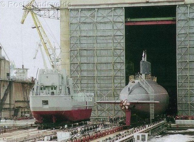
                  Hi David! Great progress on the model, but there is something i recognized taking a closer look at the stern horizontal planes and stabelizers. Correct me if im wrong. There is that one beautiful shot in your first post showing then-K-162 under construction and the stabelizers, planes and the small aft flap do NOT line up with the middle/centre of the hull but are aligned below. This is a very common design of soviet submarines of the 2nd generation, e.g. the plane/shaft configuration of the Yankee and the following Delta-class. Practical issue, building the model you would not have to design a complicated control mechanism for those planes but might use a simple straight rod. No need to build around the propeller shaft. Something i had to learn during construction of my Silent Hunter 3d models and my Delta II SSBN.

                  Jörg

                  Correction: the one small flap seems to be installed in the middle. The main planes may need to be located lower on the model.
                  Last edited by JHapprich; 06-16-2018, 01:27 AM.

                  Comment

                  • gantu
                    Commander
                    • Apr 2009
                    • 360

                    #69
                    Regards Gantu

                    Comment

                    • gantu
                      Commander
                      • Apr 2009
                      • 360

                      #70
                      Regards Gantu

                      Comment

                      • gantu
                        Commander
                        • Apr 2009
                        • 360

                        #71
                        Enjoy the videos and music you love, upload original content, and share it all with friends, family, and the world on YouTube.


                        Enjoy the videos and music you love, upload original content, and share it all with friends, family, and the world on YouTube.


                        Regards Gantu

                        Comment

                        • He Who Shall Not Be Named
                          Moderator
                          • Aug 2008
                          • 12255

                          #72
                          Originally posted by JHapprich
                          Hi David! Great progress on the model, but there is something i recognized taking a closer look at the stern horizontal planes and stabelizers. Correct me if im wrong. There is that one beautiful shot in your first post showing then-K-162 under construction and the stabelizers, planes and the small aft flap do NOT line up with the middle/centre of the hull but are aligned below. This is a very common design of soviet submarines of the 2nd generation, e.g. the plane/shaft configuration of the Yankee and the following Delta-class. Practical issue, building the model you would not have to design a complicated control mechanism for those planes but might use a simple straight rod. No need to build around the propeller shaft. Something i had to learn during construction of my Silent Hunter 3d models and my Delta II SSBN.

                          Jörg
                          I concur. Other designs placing the stern plane operating shafts above the shaft(s). KILO and MIKE come to mind.

                          David
                          Who is John Galt?

                          Comment

                          • Davidh
                            Captain
                            • Nov 2010
                            • 719

                            #73
                            Thanks David and Jorg,

                            I have to admit I haven't noticed about the stern planes being either above or below the axis line of the stern planes. I have had a look at photos of various soviet boats and have had a hard time noticing it. If their stern planes are off centre It can't be by much? I haven't noticed on drawings, not that they are dockyard and official drawings that I have access to, I don't. I also haven't seen this translated on models, (once again not dockyard models) Although I can certainly see this on the stern detail of a boat like the Yankees and Deltas.

                            I am happy with the stern set up of my Papa. The stern area is really the last remaining area to do some serious work on. I have still to keep developing the stern middle horizontal plane (flap) I will slowly work my way through that, I am probably not going to shift the horizontal plane fillets up or down a few mm.

                            Thanks for the encouragement.

                            I have turned my attention to the fin. I have sanded and smoothed it as much as I can and have decided that I really can't add to much more detail to the two side pieces. I unscrewed the two halves from each other and filled in the screw holes that I originally drilled diagonally into the bottom to join them together to ensure accuracy. After this i simply sanded back to align with the edges.

                            I then got small particle board pieces to make the mould box to fabricate the silicon mould. Drilling holes through the bottom to hold one side of the fin half to the base and then carefully making sure that the drilled holes going up into the underside of the fin and not out through the good side. I screwed down the sail really tightly so that silicon wouldn't seep under the fin piece.

                            Once the fin piece was secure I could then drill and screw in the sides to make the box. Once again I took some clay and pressed it into the sides of the box in order to seal any areas where there were gaps. Once this was done I could pour the silicon.

                            Click image for larger version

Name:	IMG_6412.JPG
Views:	115
Size:	17.1 KB
ID:	126690Click image for larger version

Name:	IMG_6421.JPG
Views:	110
Size:	17.8 KB
ID:	126691Click image for larger version

Name:	IMG_6420.JPG
Views:	117
Size:	19.0 KB
ID:	126692Click image for larger version

Name:	IMG_6413.JPG
Views:	125
Size:	16.8 KB
ID:	126693Click image for larger version

Name:	IMG_6414.JPG
Views:	125
Size:	17.8 KB
ID:	126694

                            I have also put detail into the top of the fin. Sanding a profile that carefully follows the outline of the top of the fin pieces allowed me then to mark the panels and door detail on the top. Renshape is fantastic for this.The top of the fin is a very shallow profile. This will require a thin Gelcoat layer and a thin weave layer also.

                            Enough for now..

                            David H

                            Comment

                            • He Who Shall Not Be Named
                              Moderator
                              • Aug 2008
                              • 12255

                              #74
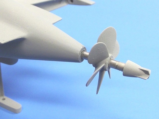
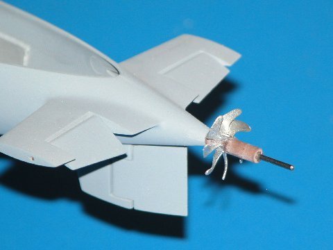
                              In an attempt to demonstrate the Soviet designers (no matter the bureau of record) pragmatic approach of how to eliminate yokes to clear a propeller shaft are the below examples:

                              An early artist rendering (I assume a Western source) of the high horizontal surfaces on the only Soviet boat of the MIKE class. A Rubin design.


                              Though a Rubin design, not Malachite as is the PAPA, this domestic variant of the KILO CLASS clearly shows the above-centerline horizontal stabilizers with attached stern planes, well above the propeller shaft.


                              The Dave Manley 1/96 KILO model showing to good advantage the above shaft location of the horizontal surfaces


                              ... and again on the Trumpeter 1/144 kit. This model representing the export version of the KILO.


                              David
                              Last edited by He Who Shall Not Be Named; 06-22-2018, 12:46 PM.
                              Who is John Galt?

                              Comment

                              • JHapprich
                                Captain
                                • Oct 2017
                                • 715

                                #75
                                Types having both the horizontal planes and the prop shaft centric: Prj. 705(K) / Alfa, Prj. 671(RT,RTM,RTMK) / Victor, Prj. 685 / Mike, Prj. 945(A) / Sierra, Prj. 971 / Akula

                                Types having the prop shaft(s) below centric planes : Prj. 667(A) / Yankee, Prj. 667B(BD,BDR,BDRM) / Delta, Prj. 670(M) / Charlie

                                661 Antchar is the only nuclear type having the horizontal planes below centric shafts that i know of.
                                But this kit is something i wished for a looong
                                time and following its way towards completion is quite inspiring to me to finish some of my own projects at the moment! So It isnt THAT important whether the planes are high or low in my case.

                                Comment

                                Working...