Scratch build Soviet Project 661 Anchar "Papa" Class SSGN K-222 1/120 Scale.

Collapse
X
 
  • Time
  • Show
Clear All
new posts
  • The Boattrainman
    Commander
    • Mar 2016
    • 443

    #31
    Hi David

    Following you work, your scratch-building is amazing.

    Funny you should mention the Apollo programme, it's another interest of mine (being the greatest achievement in human history, in my view).

    I'm re-reading the Haynes Saturn V Manual.............


    Image result for saturn v haynes


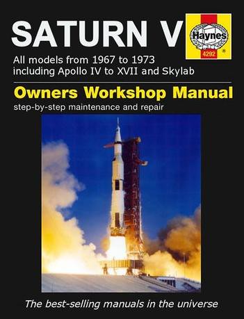
    ..............great primer on a fantastic machine (or machines).


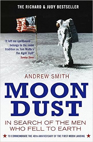
    John Watts is in this incredible book on the remaining Apollo astronauts............. one of the best (and saddest in some ways) books, as the author tries to make sense of the whole programme and the surviving guys view of themselves.


    Anyway, keep up the super model work.

    Rob
    Last edited by The Boattrainman; 01-19-2018, 08:22 PM.
    ''We're after men, and I wish to God I was with them........!''

    Comment

    • HardRock
      Vice Admiral
      • Mar 2013
      • 1609

      #32
      Hey Rob. I've got a turbo encabulator manual that might interest you. Scott

      Comment

      • The Boattrainman
        Commander
        • Mar 2016
        • 443

        #33
        Ha ha, Scott, you caught me there, I actually looked that one up!!!!!!

        Up there with the glass hammer and left handed wrench.

        Rob
        ''We're after men, and I wish to God I was with them........!''

        Comment

        • Davidh
          Captain
          • Nov 2010
          • 719

          #34
          Hi Robb,

          Thanks for the comments. I had the good fortune of meeting Charlie Duke about 25 years ago. Great speaker. Yes I have some of those Haines books and the one on the Saturn V is one I'm aiming for..


          So after creating the fillet profile for the sides and getting them in shape it was time to look at the Top and bottom rudder mounts. I have always though that the double lower rudder sections that are apparent on the Oscar would have looked good on the Papa. Oh well its only a single rudder. Still the fact that this is a twin shaft boat means that the vertical rudders with be connected with a shaft that runs straight down. No need for a bend to get around the prop shafts. So once again I followed the same procedure for making the mounts / fillets for the top and bottom rudder as I have done for the side fillet that protrude out the side of the hull.

          I took a small piece of scrap Renshape and cut out the rough profile of the base of the top rudder both the fixed part and movable surface. I then had to look at the side of the fillet and make some further cuts. The Hull slopes away as It heads towards the stern and the printed fixed rudder piece follows that curve until it meets the movable rudder the base of which is pretty much horizontal. The renshape fillet would have to follow this curve. Once I had the overall shape of the profile lightly sanded and looking good I then market out and cut the subtle V shape that would occur when the base of the top rudder section meets the fillet. I then drilled the hole for the shaft and also cut out the rectangular slot for the sprue on the underside of the vertical fins.

          As with the horizontal plane fillets I spent some time working through and aligning the holes for the drill both top and bottom. It is very easy to get this misaligned. Once done I drilled these holes and made sure that they were square in both axis. As can be seen by some of the lower photos, I didn't get it right first time, however it really didn't matter because the fillets would got over the top and only the correct hole needed to align with the hole in the renshape fillet the would fit over the top and bottom of the hull.

          I also needed to do some grinding. because the rear hull transforms into two booms that evolve their shape as they move towards the back, `This has created a Valley in between where the booms, right where the profile has to fit. I decided not to round the lower edges of the fillet to conform to the shape of the valley side as they run down and diverge as they move towards the tip. I simply decided that I would grind out a section of the sides and level them to fit the profiles as they fit in the centre. This is shown in the images with the exposed pine in between the booms. after enough grounding was done I could sit the fillet in flush with the hull surface and align it up with the correct drill hole, and lines drawn to get the profiles to sit exactly in line with the centreline To align the holes I used a brass rod. using brass rods through both ends. Once these were lined up I would simply glue it down and then squeeze filler around the sides of the profile and curving up abruptly to continue the valley sides and they run along the booms. Repeat process top and bottom.


          Anyway, enough for now, as always comments and suggestions are appreciated..


          David H


          Click image for larger version

Name:	base fillet of rudders.jpg
Views:	113
Size:	11.2 KB
ID:	124977Click image for larger version

Name:	IMG_5824.JPG
Views:	95
Size:	8.8 KB
ID:	124978Click image for larger version

Name:	IMG_5823.JPG
Views:	88
Size:	21.8 KB
ID:	124979
          Click image for larger version

Name:	IMG_5827.JPG
Views:	119
Size:	24.5 KB
ID:	124980Click image for larger version

Name:	IMG_5825.JPG
Views:	139
Size:	23.4 KB
ID:	124981Click image for larger version

Name:	IMG_5835.JPG
Views:	81
Size:	21.4 KB
ID:	124982Click image for larger version

Name:	IMG_5833.JPG
Views:	93
Size:	21.7 KB
ID:	124983Click image for larger version

Name:	IMG_5834.JPG
Views:	87
Size:	22.1 KB
ID:	124984Click image for larger version

Name:	IMG_5831.JPG
Views:	87
Size:	24.0 KB
ID:	124985

          Click image for larger version

Name:	IMG_5839.JPG
Views:	91
Size:	19.2 KB
ID:	124986

          Comment

          • Davidh
            Captain
            • Nov 2010
            • 719

            #35
            Hello all,


            After creating the fillets for the top and bottom profile, I then went around the profiles with fine 400 grit just to get the fillets to match the fins. As mentioned they are recessed lower than the profile of the section between the booms as they extend outwards. I ground out the valley to make sure that the profiles would sit reasonably flat and so make well with the epoxy applied to them.

            I mixed up some filler and applied around the fillet profile. This made for some tight corners around the sides as the curved sides of the booms comes up level with the top of the fillet. Once applied and dries I used some 80 then 240 and 400 grit to get these curves fillets smooth. A shot of grey primer helps to highlight the imperfections. As can be seen by the photos of the horizontal planes the root fillets on one side are not wide enough to extend to the trailing edge of the moving surface. This is one of several small filler jobs I will need to do around the stern end of the model.


            Click image for larger version

Name:	IMG_5841.JPG
Views:	85
Size:	22.0 KB
ID:	125014Click image for larger version

Name:	IMG_5842.JPG
Views:	97
Size:	22.3 KB
ID:	125015

            Click image for larger version

Name:	IMG_5837.JPG
Views:	84
Size:	15.3 KB
ID:	125016Click image for larger version

Name:	IMG_5838.JPG
Views:	105
Size:	16.9 KB
ID:	125017Click image for larger version

Name:	IMG_5894.JPG
Views:	91
Size:	15.8 KB
ID:	125018

            I will also have to cut one of the booms and slightly re-align as the two booms although very close are slightly out of alignment according to a centre line if drawn that extends down the middle of the hull and out past the booms. The booms also taper just a little too far and the diameter at the point where the props meet. It is a bit small. I will need to increase the diameter at this point it make the shafts of the kit fit inside the diameter at the extreme aft ends.

            David H

            Comment

            • trout
              Admiral
              • Jul 2011
              • 3547

              #36
              David, You are doing an amazing job on this, especially when I see the technical challenges with aft planes and drive shaft. Amazing.! I also appreciate your desire to get it right.
              If you can cut, drill, saw, hit things and swear a lot, you're well on the way to building a working model sub.

              Comment

              • Davidh
                Captain
                • Nov 2010
                • 719

                #37
                Hello All,

                Thankyou Trout, Much appreciated.

                I have had a busy schedule with model building over the last couple of months. I have about 3 jobs on the go all at once. I am re-tooling the hull and sail/fin of Resolution, finally getting the overall hull shape right. Then I will start the construction of a new cylinder that will better serve the re-tooled Resolution and also the Borei. This cylinder will be almost the same design as the twin shaft design for the Papa but will only be a single shaft. They will all use a separate PVC pressurised tank and a battery up forward. Also produced another hull of borei to add to the stock and will also punch out a Resolution hull.

                I haven't spent a huge amount of time lately on Papa. I would like to but did manage to get some scribing done on the forward hull. Once again I have a wooden tuned bow section that is pretty straightforward and a stern section which is where all the fun is at. The turned pine as a grain that will easily sidetrack the best of scribing efforts. So once again like Borei I marked out the location of the hatched and scribably detail I then took to the Pine surface with a dremel to cut out the are where I will be scribing. The turned bow section is not all that long and not far back so soon you are scribing into the grainless smooth material of the PVC pipe. Taking the dremel and cutting along the lines marked down for the scribable detail. The dremel can sometimes wobble a little as you move along. I light sanding over the top of the dremelled area removes any burrs and neatens the area.

                Then get the filler and mix up a batch to smooth into the grooves. Slightly overfilling in order to sand down. I have found that when you dremel a lot in a small area, fill and then sand back you tend to get a slight undulating effect over the surface that kind of gives a character a bit like oil canning, but more like slight undulation in panels that don't follow a predictable, up and down pattern. Still in the right light It looks "Russian'. Well, I think so...

                Sanding involves rough, down to smooth, I go down to 1200. Then I grab my scribing tool which is a fine pointed fine file.


                Click image for larger version

Name:	IMG_5851.JPG
Views:	98
Size:	19.0 KB
ID:	125085Click image for larger version

Name:	IMG_5852.JPG
Views:	88
Size:	16.5 KB
ID:	125086

                Click image for larger version

Name:	IMG_5854.JPG
Views:	136
Size:	19.9 KB
ID:	125087Click image for larger version

Name:	IMG_5918.JPG
Views:	161
Size:	21.5 KB
ID:	125088


                David H

                Comment

                • Scott T
                  Commander
                  • May 2009
                  • 378

                  #38
                  Since your burring out the lines would it work to put a cut off saw blade in your dremel and trace the
                  lines with it. It might not wonder across the surface as much as it moves more linear compared to a
                  rotation of the bit.
                  Or razor saw the straight lines.
                  Last edited by Scott T; 02-09-2018, 01:02 PM.

                  Comment

                  • Davidh
                    Captain
                    • Nov 2010
                    • 719

                    #39
                    Hi Scott,


                    Yes, if the lines are long enough I will use a tiny hobby saw that reminds me of the larger Japanese woodworking saws but with a finer blade and kerf less.I will even angle one of these blades in an already scribed groove and work it further. It does work quite well, you just need to make sure that the line is already established so that the blade wont wander.

                    I haven't been able to do too much on Papa at the moment, as mentioned previously side tracked by trying to get Resolution re-tooled and up and running. This is slowly getting there, I've created the silicon moulds for the revised larger and wider stern planes for Resolution and they are looking the part.

                    I intend to get back to some more Papa soon, however I have continues with the etching and scribing along the hull. As can be seen I scribed along to about the location of where the fin starts, scribing the Cruise missile doors around both sides of the forward hull. I still have more detail to work on as there are some free flooding vent beneath the missile hatches that I have yet to do. However once again I marked out the location of the hatches and detail to the rear of the fin, then got out the Dremel and started grinding out the channels needed for a layer of filler that would go on soon enough. Once again a mix of working with PVC pipe which is really easy to scribe in and the pine that requires the special treatment.

                    There are several drawings available of Papa and like the Mike, there is some variation between them when it comes to deck detail and safety lines. I simply had to pick one that looked like it would best conform to the images I have of Papa, which is frustratingly limited. As mentioned previously, this boat was about for 30 years, Didn't anyone think of taking more photos than just the few available? Seriously.
                    This has meant a little bit of interpretation when it comes to deck detail and also some looking over features that would be commonly "Russian' like escape hatches and the like.

                    I have scribed most of the stern section of the boat , just forward of the stern rudders however I haven't touched the stern escape hatch that is just in front of the vertical fin.


                    Click image for larger version

Name:	IMG_5915.JPG
Views:	98
Size:	16.2 KB
ID:	125178Click image for larger version

Name:	IMG_5925.JPG
Views:	94
Size:	12.6 KB
ID:	125179Click image for larger version

Name:	IMG_5919.JPG
Views:	83
Size:	18.3 KB
ID:	125180Click image for larger version

Name:	IMG_5922.JPG
Views:	89
Size:	12.2 KB
ID:	125181Click image for larger version

Name:	IMG_5924.JPG
Views:	85
Size:	21.5 KB
ID:	125182Click image for larger version

Name:	IMG_5927.JPG
Views:	93
Size:	18.4 KB
ID:	125183


                    Comment

                    • Davidh
                      Captain
                      • Nov 2010
                      • 719

                      #40
                      Hello All,


                      I haven't really used Renshape before but have made the fin out of this new material (well, new to me). A month ago I managed to cut out the overall profile of the fin. This material is not what I expected. To me the texture kinda reminds me of stone, sandstone in particular. However agreed its fantastic to work with.

                      I originally made the fin oversized, its too high and a little too wide. This simply gave me more material in which to secure the parts together. I have gone with two self tapping screws going up from underneath at about a 45 degree angle. I just hoped that when I reduced the fin I would not find little tops of the screws sticking out.

                      I printed off the top of the fin after designing it in blender. It has a narrower cross section than the foam part of the sail and so would need to be sanded down. Its a little frustrating as the thinness of the 3D print means that the top piece is bowing upwards. I'm not really concerned when I mould this I'll glue it down firm to the moulding board. The Papa has a very stock sail. It is quite short and log. I am assuming that this is a function of the high speed that the sub generated. It also has little taper from the bottom to the top. The most distinctive feature of the fin this the noticeable curved bulge along the front of the fin that extends from the top front down to about 30 % up from the base. It also features a wrap around array arrangement that can be seen as a series of subtle panels outlines. This is typical of numerous Soviet submarine designs with a sonar array wrapped around a curved surface. It reminds me of the array that features on the bow of the Foxtrot. class diesel boats.
                      This is one of the best photos taken of Papa. Even though It was taken after de -capitation. It shows some really good detail of the fin and you can see the rectangular pattern that wraps around the side and front of the sail. Its a pity that I cant get the same pic of the other side.

                      Click image for larger version

Name:	IMG_3001.JPG
Views:	202
Size:	185.5 KB
ID:	125286

                      So after looking at the drawings, I took the fin and with a marking gauge measured the amount to be taken off and then scribed a line around then simply cut it off with a hacksaw. Then a light sanding and a little more on a flat board to get it square. Once that was done I marked around the top of the sail with the printed out top piece and then started sanding around all the sides to get the fin to the right width at the top and a little wider at the bottom. I made a bottom profile to make sure that the bottom shape would conform and then sanded till both top and bottom edges met the rim of the outlines.

                      Click image for larger version

Name:	IMG_5949.JPG
Views:	94
Size:	14.6 KB
ID:	125287

                      Click image for larger version

Name:	IMG_5950.JPG
Views:	87
Size:	16.9 KB
ID:	125288Click image for larger version

Name:	IMG_5951.JPG
Views:	92
Size:	12.9 KB
ID:	125289
                      Click image for larger version

Name:	IMG_5952.JPG
Views:	90
Size:	11.7 KB
ID:	125290

                      The bulge at the front has turned out well even though I needed to smooth out the abrupt line at the start of the curve.


                      David H

                      Comment

                      • Davidh
                        Captain
                        • Nov 2010
                        • 719

                        #41
                        Hello All,

                        The Sonar bulge in the front of the fin has too much of a pronounced lower curve so with some 180 grit I managed to smooth down the lower are where the bulge occurred to create a smoother transition. To make the sonar panel at the front I decided to cut up a coke can, cut out a rectangular section and then draw lines along the back of the sheet. Once done I took a fine point on the back of a small file and used as a scribe to crease lines along the back of the sheet to resemble the rectangular pattern. After turning over the sheet you could clearly see the pattern showing through the sheet.

                        I spent some time curving the sheet as the gentle bulge in the front of the fin would also translate to the sheet. I took scissors and made some small cuts at the top and bottom of the sheet along the lines of the grooves to the first horizontal crease line. I would then work these cuts to overlap the panels along the first line of rectangles to make the top and lower sections curve in and simulate the inward curve along the top and bottom. After working out where the panel would be glued I mixed up some epoxy ,applied the resin and then clamped down the sheet to the front of the fin.

                        Once glued I then mixed up some filler and worked it around the sides where the sheet meets the surface of the Renshape profile underneath. Once this was hardened I simply sand over with some 180 then moving up to about 400. The transition between the edges of the sonar panels and the Renshape will need some substantial sanding and further filling to create a seamless transition between the two.

                        Click image for larger version

Name:	IMG_5953.JPG
Views:	114
Size:	14.8 KB
ID:	125381Click image for larger version

Name:	IMG_5954.JPG
Views:	93
Size:	16.7 KB
ID:	125382
                        Click image for larger version

Name:	IMG_5955.JPG
Views:	95
Size:	16.9 KB
ID:	125383Click image for larger version

Name:	IMG_5957.JPG
Views:	100
Size:	15.3 KB
ID:	125384
                        Click image for larger version

Name:	IMG_5961.JPG
Views:	96
Size:	13.1 KB
ID:	125385Click image for larger version

Name:	IMG_5962.JPG
Views:	106
Size:	15.9 KB
ID:	125386


                        Once sanding back the outline of the sonar section I started marking out the doors and access panels along the sides of the fin. Renshape is fantastic to carve into.


                        Anyway, any comments or suggestions would once again be appreciated..

                        David H

                        Comment

                        • Davidh
                          Captain
                          • Nov 2010
                          • 719

                          #42
                          Hello All,


                          After scribing in some of the detail for the doors and access panels I then marked out a thing line across the lower sides of the sail to mark out the location of the hand rails that are located along the side and go from the front of the fin and align up at the back. I use really thin styrene to simulate the handrails. I light shot of primer.

                          I have gone back the hull and applied a little more sanding to the widened mid section that curves around the base where the fin meets the hull. There were some slight imperfections and so once this are was smoothed and even I started to mark out the limber holes and other hull details around the amid ships either side of the sail. Once again taking a fine round scribe and etching the markings as required.

                          Click image for larger version

Name:	IMG_5967.JPG
Views:	86
Size:	16.8 KB
ID:	125538Click image for larger version

Name:	IMG_5959.JPG
Views:	82
Size:	16.6 KB
ID:	125539Click image for larger version

Name:	IMG_5964.JPG
Views:	97
Size:	14.9 KB
ID:	125540Click image for larger version

Name:	IMG_5973.JPG
Views:	82
Size:	17.6 KB
ID:	125541Click image for larger version

Name:	IMG_5974.JPG
Views:	85
Size:	17.8 KB
ID:	125542Click image for larger version

Name:	IMG_5976.JPG
Views:	90
Size:	20.5 KB
ID:	125543

                          Comment

                          • Davidh
                            Captain
                            • Nov 2010
                            • 719

                            #43
                            Hello All,

                            I have gone back over the drawings of Papa from the top view and realised that the stern in between plane is further back than the outer stern planes. It is not aligned with them. I had built the rear hull so that the mounted section where the inner plane fits is just at the rear line /trailing edge of the moving plane. I would have to move it back. I have also spent a fair amount of time looking at the two stern booms as they extend outwards. Checking that they extend out at exactly the same angle and to the same length. also making sure that the diameter reduces at the same rate on each as out move sternwards. Better to get these things checked now before going all the way to moulding stage and then noticing the imperfections. This as happened to me enough times on Resolution!

                            I marked out two lines that run down the axis of the two stern booms towards an arbitrary point just beyond the vertical fin. This helps me to look over the angles of the booms and make sure they are consistent. One of the things that I have noticed is that if the booms are not quite symmetrical it will have an effect on the fillet profile of the horizontal planes as they are so close to where the booms diverge towards the very stern. The shape and outline of the rearmost section of fillet as it curves back towards the boom is subtly different. You can clearly see a difference on the template photo.

                            HWSNBN is a great user of templates. I have also made a few in my modelling and they certainly help to clarify and articulate what you can't quite pin down. I have created a small template where the angle of both booms can be measured. As can be seen on this template the angle is set at 78 degrees and the distance apart from the centre axis is 24 mm. I'm out by 1 mm on one.

                            Click image for larger version

Name:	IMG_5987.JPG
Views:	92
Size:	18.6 KB
ID:	125639Click image for larger version

Name:	IMG_5985.JPG
Views:	89
Size:	18.4 KB
ID:	125640
                            Click image for larger version

Name:	IMG_5991.JPG
Views:	100
Size:	17.4 KB
ID:	125641Click image for larger version

Name:	IMG_5988.JPG
Views:	85
Size:	17.2 KB
ID:	125642
                            Click image for larger version

Name:	IMG_5990.JPG
Views:	86
Size:	14.6 KB
ID:	125643Click image for larger version

Name:	IMG_5784.JPG
Views:	236
Size:	174.1 KB
ID:	125644

                            The lower photo shows a correction in the rearmost fillet curve. the port side needed a little more filler to widen and bring out the curve just a little more. Throughout the process I have been interchanging the stern planes assembly on either side. All horizontal planes should line up on both sides. The fillet should be an exact align for either left or right.


                            I would really appreciate it if anyone has any other pics of this elusive boat, I would certainly love to see more detailed pictures of her. As mentioned before, there are very detailed internal drawings of this boat that are available. I have seen them and printed them out but if anyone has outer casing details in photos that are not well known or obscure that would be great and would certainly help me attain greater accuracy.

                            Once again , like Mike, I emailed the Malachite design bureau to see if they would part with any information. However, typical Russian response. Not even a reply...

                            Enough for now..


                            David H

                            Comment

                            • gantu
                              Commander
                              • Apr 2009
                              • 361

                              #44
                              Regards Gantu

                              Comment

                              • Davidh
                                Captain
                                • Nov 2010
                                • 719

                                #45

                                Thanks Gantu,

                                I actually have pictures of that model. Interesting how there are differences between the model and the drawings I have. But then again none of the drawings align.

                                I have am still in the fine tuning of small appendage parts stage at the moment. I will continue using small amounts of filler to get the parts just right. I have spend a couple of hours just filling in tiny areas of the props and then sanding them with very fine wet and dry to get them just right. They are about as consistent with each other as I can make them at the moment. I have also had to place some filler around the root of the stern planes as there is a 'rim' where there is a slight rise all the ay around as the part then buts up against the fillet profile on the rear hull. It I don't reduce the radius at this point it will not make such a smooth gradual transition that would have been what the original boat would have had. I intend on getting this resolved soon.

                                I have spent a bit of time lately just going over the hull and looking at the scribe work. Some areas where it looks a little shallow I have gone over again to get just right with a little more depth but taking care not to make it any wide and fudge it. This week I managed to scribe out a few more drainage vents, mainly the MBT vents along the bottom of the boat. Papa seems to have its vents quite wide out to the side. They are not directly underneath. I have also added some drainage ports that are directly underneath the large cruise missile doors at the front. This boat had a lot of vents!

                                Doing this I noticed that the Missile doors on the starboard side a slightly lopsided. they are further away from the centre point line that runs down the axis of the boat along the top. Don't you just hate that! I worked out that I would simply have to reduce the top line of the missile doors at the top by about 5mm and increase the edge at the bottom downwards by the same amount. So that's what I did. Filler, sanding and then some etching and it looks even now.

                                Click image for larger version

Name:	IMG_6077.JPG
Views:	79
Size:	20.9 KB
ID:	125720Click image for larger version

Name:	IMG_6078.JPG
Views:	74
Size:	18.2 KB
ID:	125721
                                Click image for larger version

Name:	IMG_6079.JPG
Views:	87
Size:	15.3 KB
ID:	125722Click image for larger version

Name:	IMG_6074.JPG
Views:	83
Size:	12.8 KB
ID:	125723

                                Comment

                                Working...