
Once again Tom, you are Blazing a trail that others will follow, including me. Great thread! I will watch with interest. Please chronicle all your mistakes and all the kits short comings so that we will know what to watch for. You are on the point and we are bringing up the rear. As you "Take Fire" we will be watching from the safety of our computers. LOL
-
Last edited by greenman407; 11-30-2013, 07:25 AM.IT TAKES GREAT INTELLIGENCE TO FAKE SUCH STUPIDITY! -
Mark, I will chronicle my mistakes when they happen, oh look your wish is my command..... That did not take long.
Oh where to begin......
I did not get the melamine board, but while at a craft store, I got a pine base (first of many mistakes). It was warped a small bit and my upright, I did not put a angle in the back for support.
I did not think that out so well. But hindsight is 20/20
CA'd a strip of 100 grit sandpaper onto the center of the board to hold it in place. I did use tape to hold it. The blade was put into the Foredom hand piece. It should have been put in deeper (another mistake).
Once cutting started, it would begin O.K., but soon several factors came into play. One the Foredom slid off center so the blade was cutting at an angle. Two the blade would pull up or down and the warped base allowed movement. Then three, the bit slid out and began to wobble.. So that gave me this:
All over the place there were gouges and butchered cuts. I was angry and I just got ticked off the more I cut. So, more work for me. Here is the aft and bow.
The top came off and for fun, I put the sub-driver in. Here is a panoramic, photo stitched image.
There is a lot of space in there. It is interesting to see how the model's supports came out. It held the WTC well and gave me an idea of how it would come together.
Next photo is the bow vertical cut. The aft end of the bollard is the reference point for the cut.
Before the halves were put together, I should have taken more time to remove more of the internal supports put in the sub. I thought I can just remove them later, and I can, but doing it before would be so much easier.
A couple of quick notes about the sub-driver. A look at the seals and the line of o-ring contact was real good.
But the best part for me is this modification. The SAS plumbs the air out of the WTC from the battery compartment and not the engine room. I like that better. Plus I can put a desiccant below the opening to keep things dryer.
If you can cut, drill, saw, hit things and swear a lot, you're well on the way to building a working model sub.Comment
-
Tom, are you using the Sub-Driver that David worked up specifically for this model, or are you using the standard (longer length) 1/96 Sub-Driver?"Wir kommen ihnen unbekannt."Comment
-
This will be a longer post than normal, need to get caught up.
I cut a couple of notches out of excess on the sides to allow the sub-driver foundations to fit against hull.
CA'd the bow sub-driver foundation in. The fit was O.K., not perfect. The hull did not touch near the top. I could bend the hull in to make it fit, but that would be distorting the hull shape.
The aft foundations I did not let them meet in the center, but went for fit against the hull. Great fit just does not meet in the middle. Might put something in-between to firm up the hull.
The anchor foundation with indexing pin and velcro strap fits in the middle of the box I left in. Toying with the idea of leaving it as it will allow me to add weight in there.
One of the bonuses was the men David created and I can see that these are to be considered a freebie in the kit. The casting on these are not up to the usual standard that I see in all the other parts. Lots of big bubbles and incomplete casting. As you can see, the neck on one gentleman had a bubble that allowed the head to fall off. The second picture you can see light through the elbow. The hands on second is missing and the man with hand behind the back is incomplete. All fixable and would like to use.
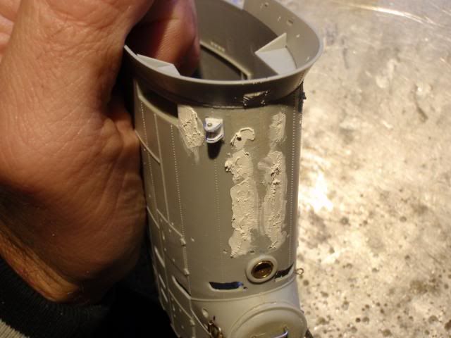
Earlier I admitted to my shameful cutting of the hull, but with big mistakes come big repairs. Well not such a big deal. I love the Evercoat Metal Glaze because of the way it sands. So I had a thought of using it to fill the irregular cuts. I set my hull piece on the melamine board oriented as if it was on the lower hull (top facing up). Then used tape to carefully layout a straight level line. Inside the hull piece I could only approximate being equal to the external tape. What it left me was two pieces of tape with a gap between them. I planned on filling the void with the glaze.
I tried to be careful and move the spatula inside trying to remove the bubbles or voids.
After all was done and set up,the tape was removed. There were a few areas that needed to be filled in after the fact, but not a big deal. Mixed up another batch and tried to push the glaze into the areas that did not get filled.
The exterior Looked pretty good. There will be some filling needed and sanding. I think this will work.
The conning tower (please forgive me if this is not the correct term) is amazing! The detail is just stunning. Great work Bronco!
The conning tower fit together oddly. What I mean is, when the front was together the aft end had a warp to it and if it was pressed to fit the seam on the forward edge had a slight gap. What I did to overcome this was to use cohesive glue on the very front seam, making sure to align it well. Let that set. The exhaust fairing was next, small sections at a time getting it to fit and letting it set.
Back to awe on this sub's detail. I almost trimmed this off thinking it was a mold injection tab sticking out, but on closer inspection it is a loop.
Left the back open (you can see how it fit) until I know how the CT will go together.
Last edited by trout; 12-02-2013, 02:12 AM.If you can cut, drill, saw, hit things and swear a lot, you're well on the way to building a working model sub.Comment
-
Excellent work Tom, you lived the nightmare and solved your problem, as for that loop at the top of your conningtower, cut it away,
It has to look like this, you're clever enough to reproduce this with some styrene, projected it like Bronco did, it won't allow you to walk across the front deck without messing with your antenna wire, often also used as a safety wire to hook up for the crew.
Manfred.I went undergroundComment
-
Thank you Manfred. I will cut that off. The way you are holding the conning tower makes me think you are hiding something......what did you create?If you can cut, drill, saw, hit things and swear a lot, you're well on the way to building a working model sub.Comment
-
Due to the secret nature of the SkunkWorks i cannot answer your question, i'm being monitored by a censor, to be short, nothing to hide, just a silly way to hold up the conningtower.
Manfred.I went undergroundComment
-
Aw, that is sad. I thought for sure you had something going on there.If you can cut, drill, saw, hit things and swear a lot, you're well on the way to building a working model sub.Comment
-
Just a little done tonight.
Acetone bath and scrubbing followed by a very warm sudsy water bath. Rinsed and let dry.
Before installing you will need to pre-shaped the bow radial flange so the fit will be easier to glue.
Used cohesive glue to affix it. I placed these with about half overlap with the hull, just made sure it did not show through the limber holes. The strips I received were shorter than David's documentation. If needed I can add another piece or two to lengthen these flanges.
The aft radial flange was also shaped to fit, but once the glue was placed on the flange it split. I attached one side then the other. It might have been better to have more of the flange exposed, but I think this will work.
Tomorrow night I will do a little more clean up on the seams and we will see what else.Last edited by trout; 12-04-2013, 03:48 AM.If you can cut, drill, saw, hit things and swear a lot, you're well on the way to building a working model sub.Comment
-
Hi, Tom!!
The crazy one, here, has found you with your latest build!! Am certainly a big fan of your "gotta-do-what-ya-gotta-do"
methods!! Most informative and lots of "food-for-thought"!
Will be following your build with great interest, as usual. Your open willingness to share all with we "newbies" is most appreciated.
All ahead full, Admiral! We, your devout crew, have your back!!Comment
-
Gary,
You have been quiet recently. How are the builds going?
I am glad you enjoy this WIP. Friends like you make it worth it.
We are back to back brother.
Peace,
TomIf you can cut, drill, saw, hit things and swear a lot, you're well on the way to building a working model sub.Comment
-
Hiya, Tom!!
Great hearing from you! Looks like you've been having way too much fun!! Put a little time into my model railroad while waiting for sub stuff to arrive, as well as still researching to build a viable, and nicely operable, piston tank ballast system for my Kilo! I think I'm onto something pretty good utilizing a 2.9 gram linear servo to operate the piston! Will know when parts arrive! (Film at 11!)
Have spent some time opening up vent holes in the lower hull half of my little Skipjack.
Side tracked myself at the prospect of building the Kilo, instead!! Gees!! Decisions, decisions!! Hah!!
Still haven't given up on r'cing my little 1:350 Hobby Boss USS Virginia!! David likes to refer to these little guys as "Faberge Eggs"!! Will require a 1" diameter wtc, which I'm pretty sure I can pull off! Plenty of really small components out there! All ya gotta do is research, and give it your best shot!
The knowledge I can gain from building my own wtc for the Kilo, should prove invaluable in going ahead with the Virginia!
So much cool stuff; so little time!!
Best of everything to you on your current build, and I will definitely be keeping an eye on ya! You are always a great
"go-to-guy" for plenty of inspiration!!
Looking forward to your eventual sea trials!!
Git 'er done!! (LOL)
crazygaryComment
-
Thank you Gary!
The rudder is disassembled. The axel was very tight to remove, needing pliers to pull out. You can see that the axel has a flat surface ground into it. This is where the grub screw will sit against to prevent slipping on the axel.
Made a z-bend on a pushrod with one of my favorite pliers and put a tiny touch of CA onto the pushrod where it meets the dive rudder bell-crank horn. Here you can see that I can turn the pushrod 90 degrees and the bell-crank does not flop around. The bond is easily to break and allow the pushrod to move freely.
Drilled a 1/8" hole on the topside of the rudder and fed the rudder axel/shaft through the bell-crank and down through the rudder. Tighten it all up. The set screw or grub screw on this blew-crank is a paint in the tuckus. After everything was set up is still seemed to slide, but I could not see down to the bell-crank (maybe during daylight.
Compared to the rudder, the rear dive plane is a breeze to install. I did need to ream out the holes for the shaft of the rear dive planes a tiny bit. Then once installed (which was super simple), one plane was not tight on its axel/shaft. So much so, that it could not support it's own weight. I am going to assume that these are to be attached with RTV rubber?
Here is a shot of the bell-crank on the rear dive planes.
The bow planes were the easiest to install. For this on I used one complete length of 1/16" brass wire for the pushrod.
Long length of brass wire being used for the pushrod.
I am going to route the wire down the side of the sub-driver over the flat tops of the sub-driver foundation on either side of the hull. We will see how that works.Last edited by trout; 12-06-2013, 03:43 AM.If you can cut, drill, saw, hit things and swear a lot, you're well on the way to building a working model sub.Comment
-
Did not get a chance with daylight to try to tighten the rudder bell-crank set screw. Might need to cut open the hatch. The swing I get is very impressive. Thinning the wall and slight removal of material from the bell-crank horn/arm really made a huge difference. There is way too much for tmy needs, so will connect the pushrod on the servo arm on the innermost hole. Then if that does not reduce the throw enough, adjust it at the TX.
I am going to experiment on the location of the sub-driver (Andy do not yell at me). So to begin, I will put it center of the sub. To do this, I drilled some holes underneath the sub-driver with 3/32" drill, hand twisted. Now I can move the sub-driver to different locations as I test (yes, I will need to redo all the connections to the dive planes and re-trim the sub)
Once set onto the indexing pin there was a slight rise aft on the wtc. It did not show up on this picture.
However, here you can see what was causing the rise and the simple fix.
The last issue with having the indexing pin underneath the vent is the velcro strap. To prevent the strap from covering the vent, there is a slight offset in crossing the velcro, an X if you will.
If you can cut, drill, saw, hit things and swear a lot, you're well on the way to building a working model sub.Comment


Comment