today's work

Collapse
X
 
  • Time
  • Show
Clear All
new posts
  • He Who Shall Not Be Named
    Moderator
    • Aug 2008
    • 12253

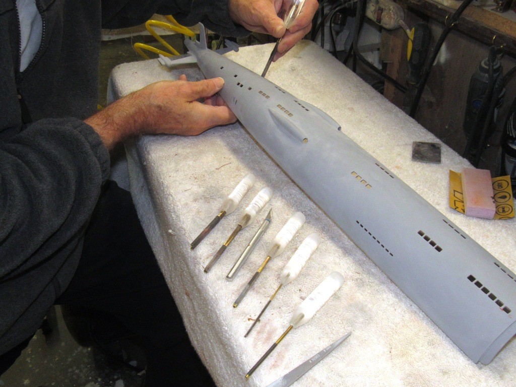
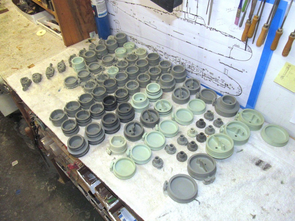
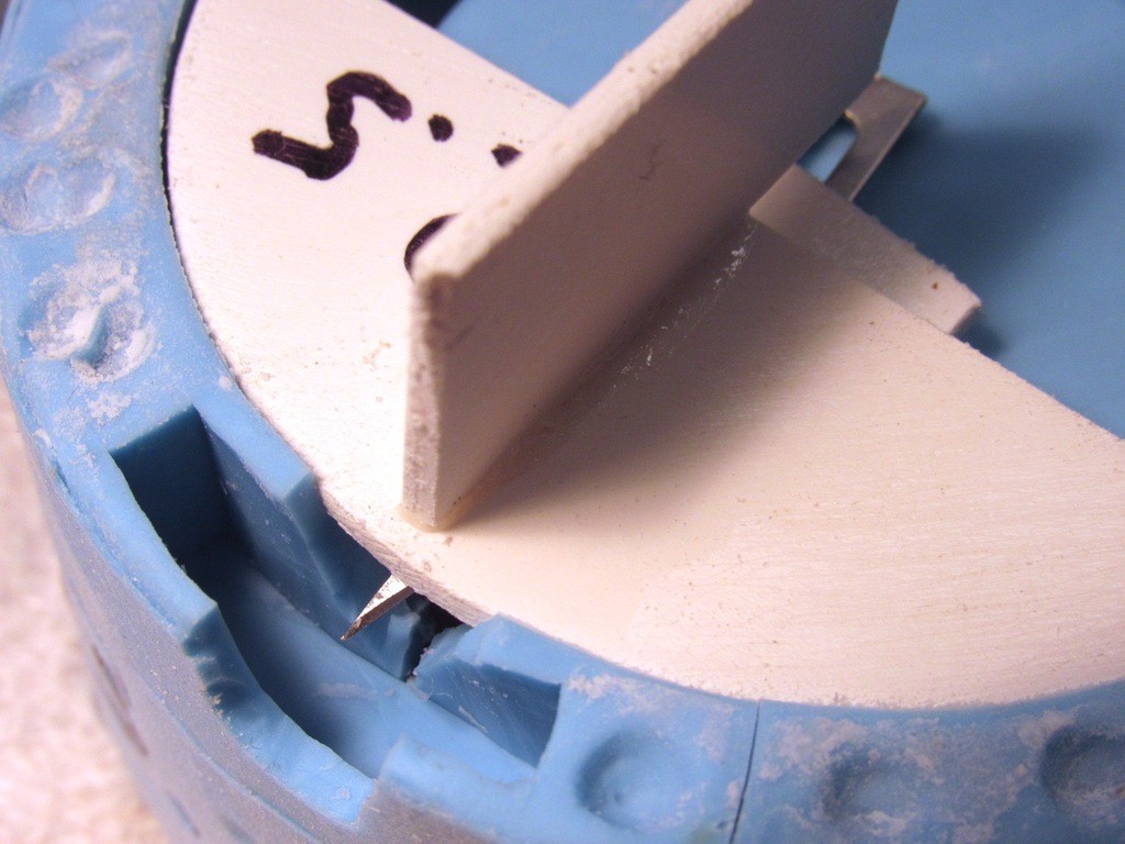
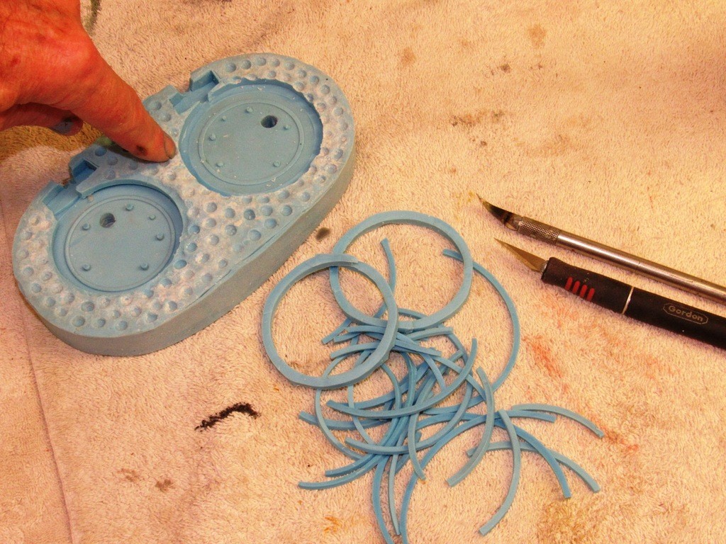
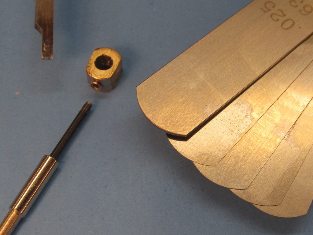
    Special sanding tools were made and used to refine the shape of the many different sized and shapped limber, flood-drain, and vent holes along the length of the ALFA’s hull.

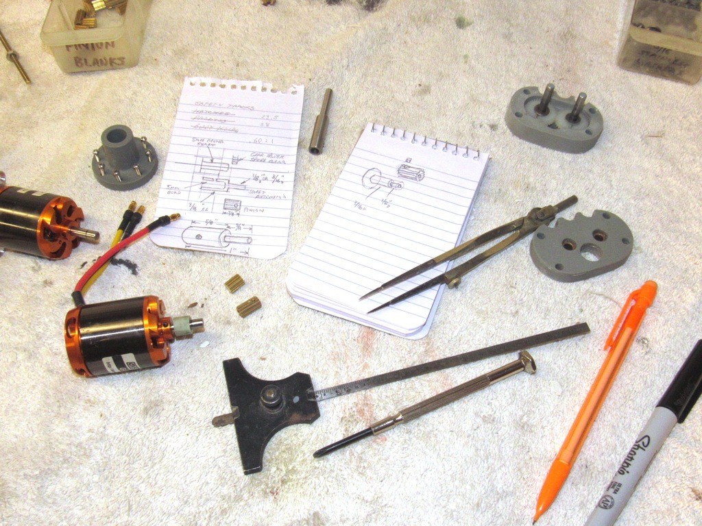
    Scratch-building would be a joy if multi-view orthographic drawings of the subject are at hand. But, in the real world the smaller items of a subject presented as a plan are done so with few if any enlarged auxiliary views that would reveal the intricacies of these smaller items. So, by necessity, photographic interpretation is a big part of documentation enhancement that has to be done by the careful modeler. A valuable tool in your inventory of skills is the ability to generate your own ‘shop sketches’, based on study of still and video images of the prototype. Such renderings helping you identify the geometry of the object being rendered as a three-dimensional model.

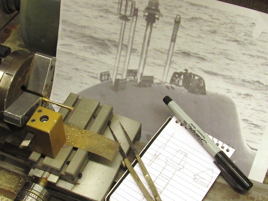
    Just such a drawing used to assist me as I turned a length of machine brass round-stock to form the ALFA’s only periscope – a big ugly thing definitely not intended for close-in attack duty. Most of this item was lathe turned, but the scope head itself had to be carefully carved shaped by hand using riffler files, knife, and moto-tool burrs.

    Something the Russian submarine design bureaus did little about, until recent years, was the use of streamlined mast fairings to streamline the cylindrical retractable masts to the water flow. As a submarine travels at speed the drag of the water passing around the cylindrical mast will, at some critical speed, go turbulent and will, like clock-work, induce a vibration onto the mast. Mast vibration will interfere with the optics of a periscope, or the wave-guide efficiency of a high-frequency antenna system. That same mechanical vibration also presents a strain on mast seals and shears. The inevitable vibration problem addressed to some degree by the Russian practice of making their masts of (by American standard) very large diameter steel tube.

    However, these simple mast cylinders are a god-send to the lazy model-builder, like me: a length of aluminum tube, cut to appropriate length, topped by a cast scope, snorkel induction, or antenna and I’m done!

    Most Russian designed boats feature these simple tubular masts. Our Russian counterparts did not employ mast fairings till later versions of the KILO class boats came off the building ways. Nowaday’s Russian boats employ streamlined fairings on most of their retractable masts… welcome to the 21st century, Ivan!

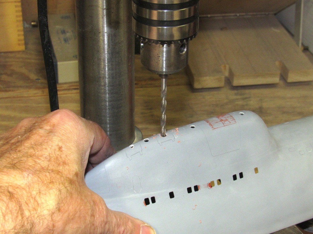
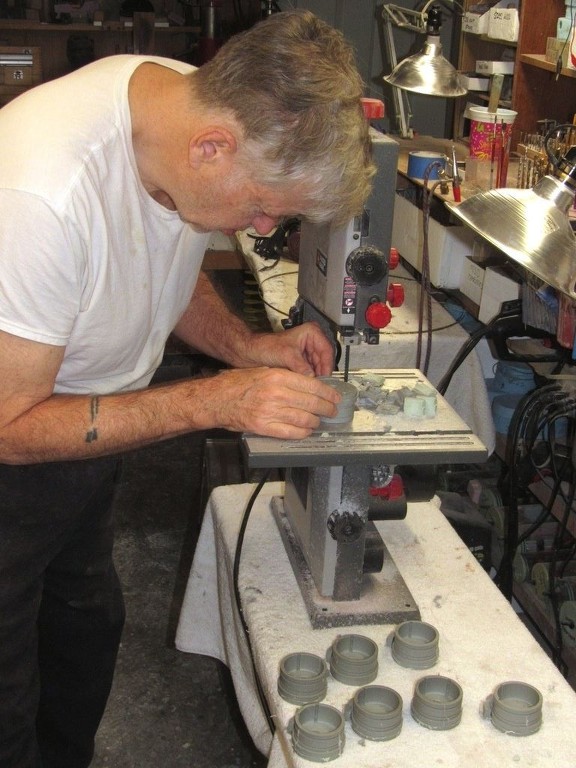
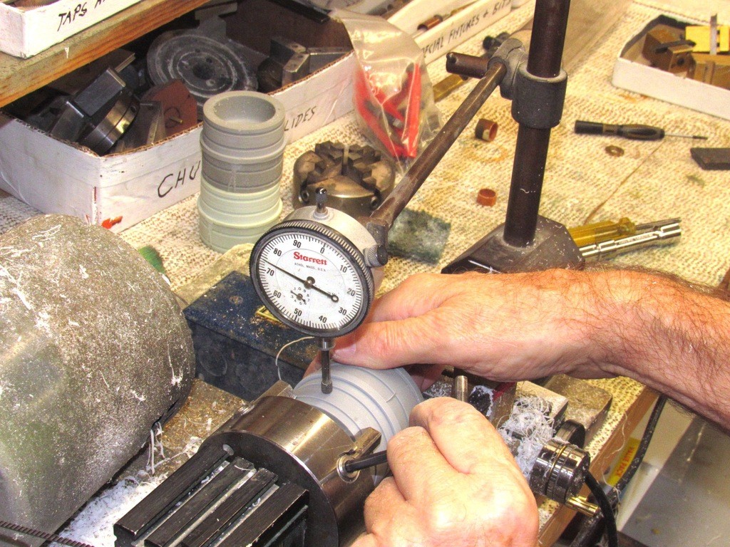
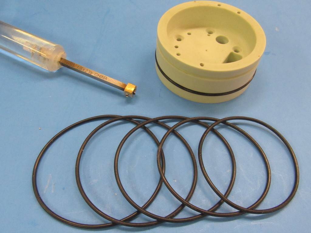
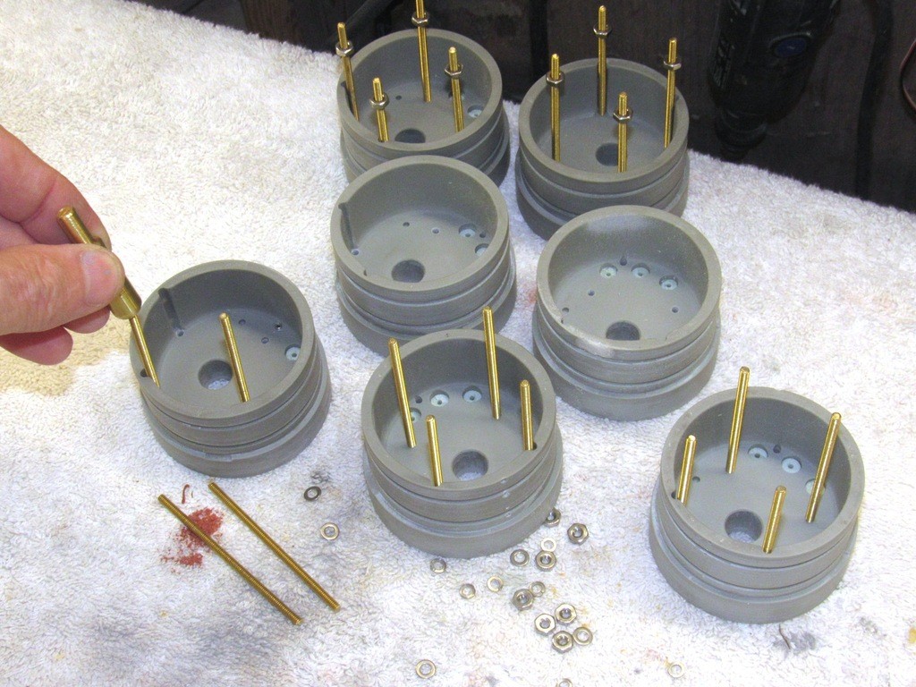
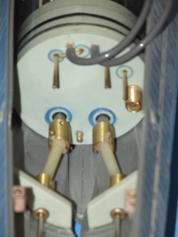
    Once the RenShape mast foundation piece is glued within the top of the sail the upper hull is positioned onto the bed of the drill press and the appropriately sized bit is used to drill a perfectly aligned hole through the foundation, forming a interference fit between it and the base of a mast.

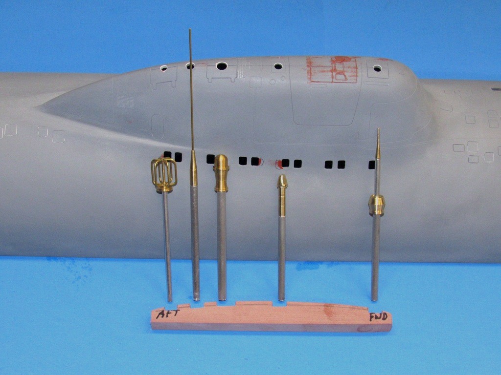
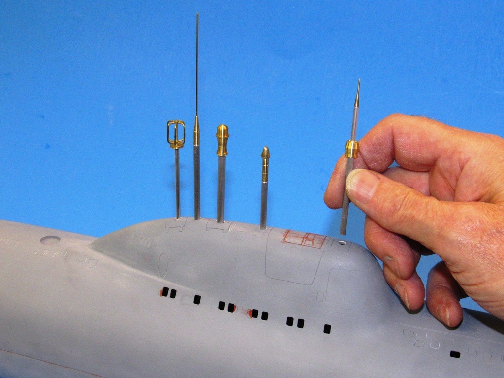
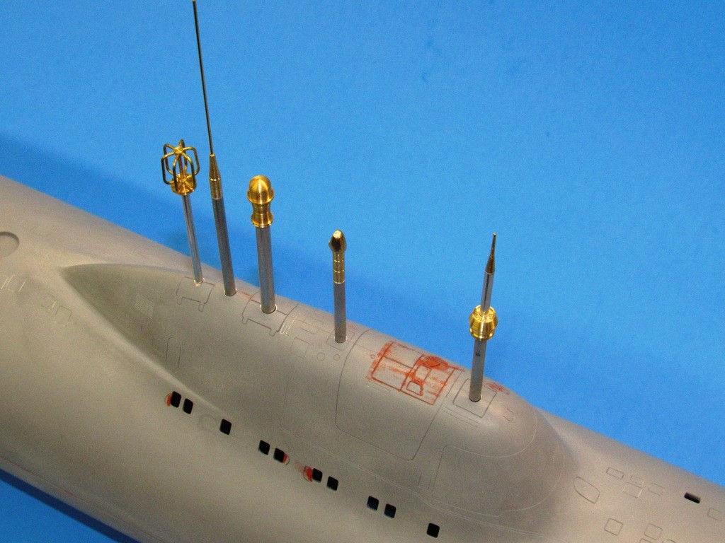
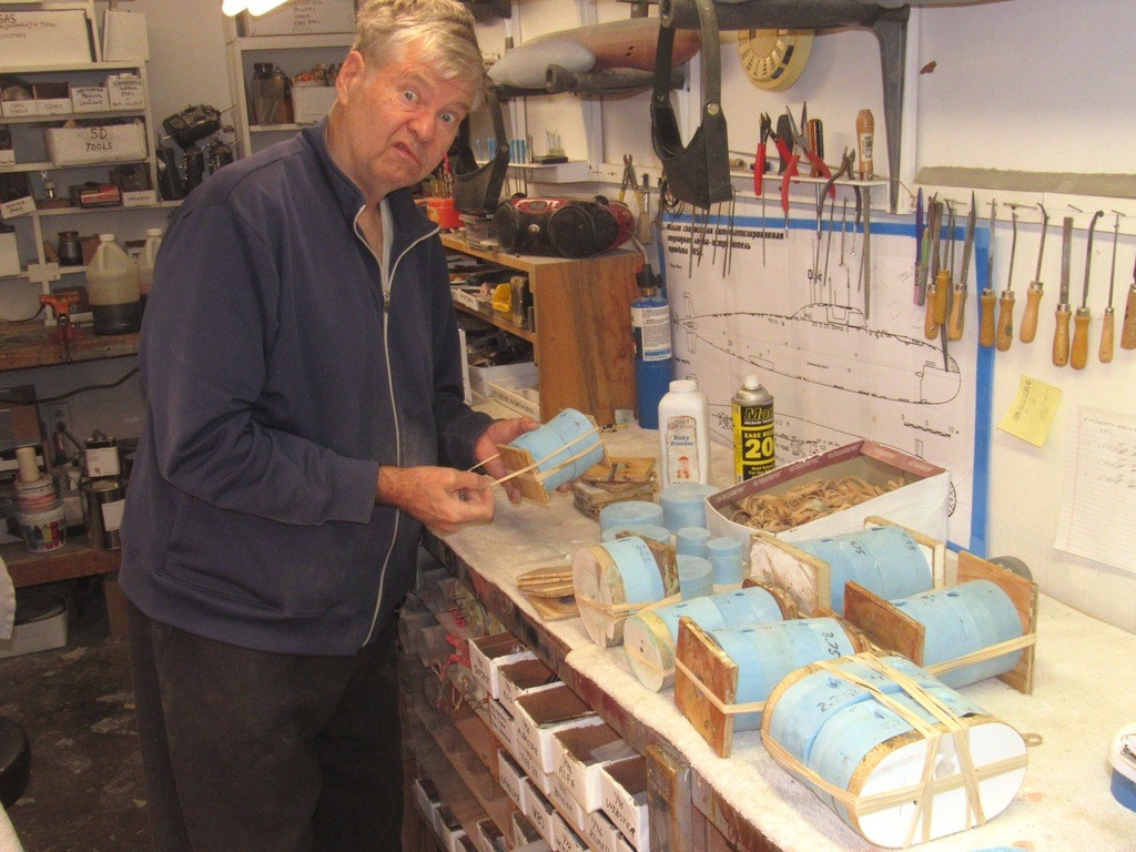
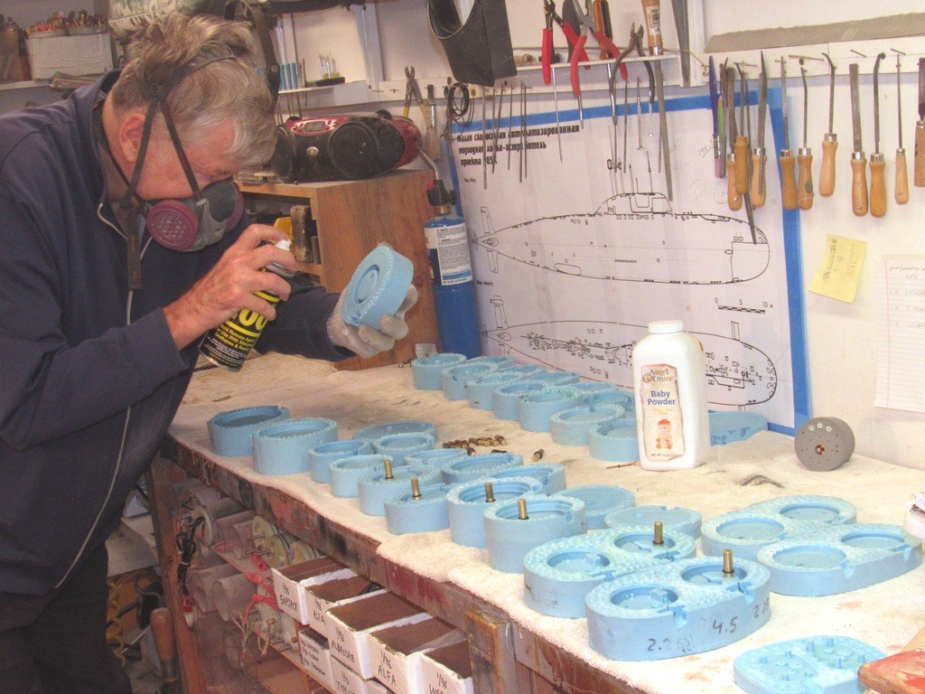
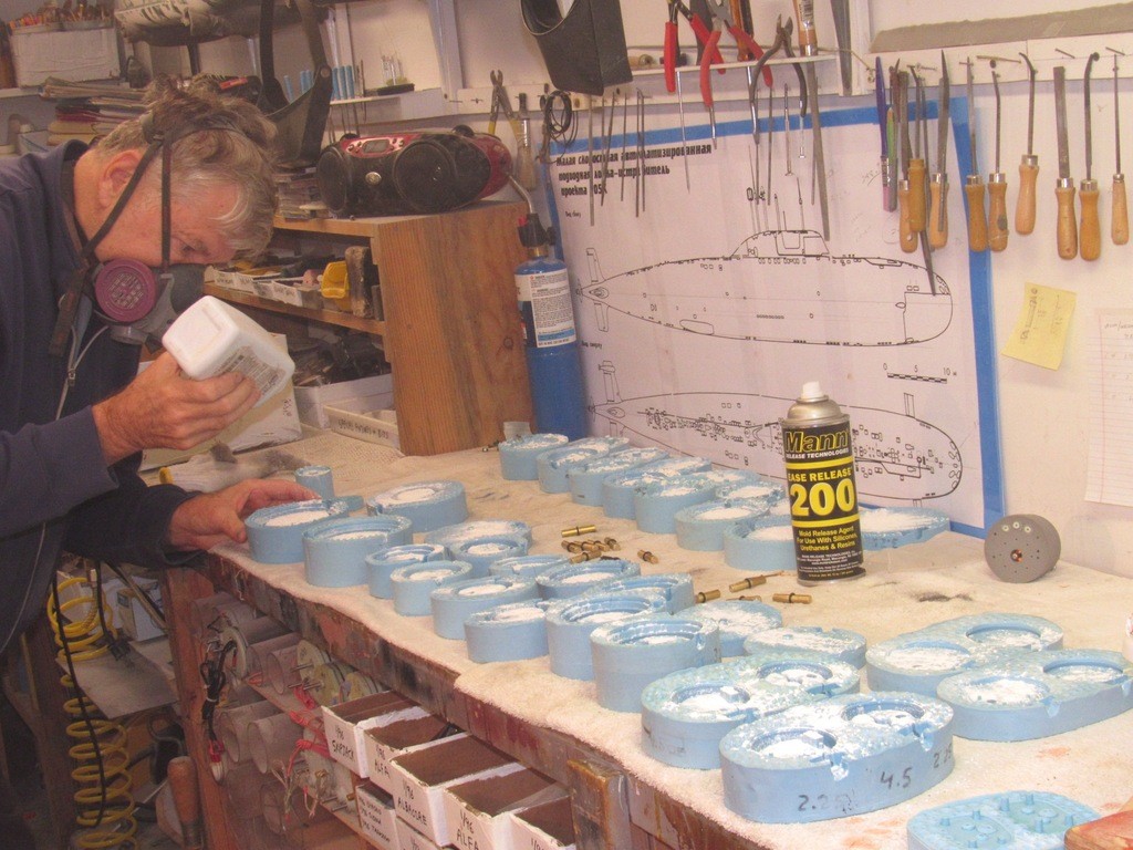
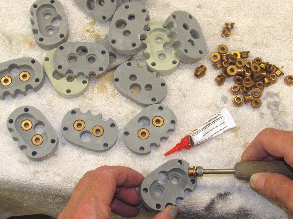
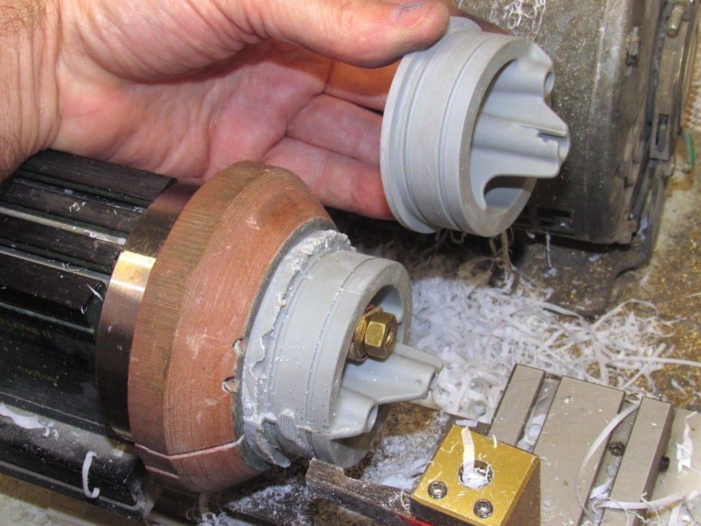
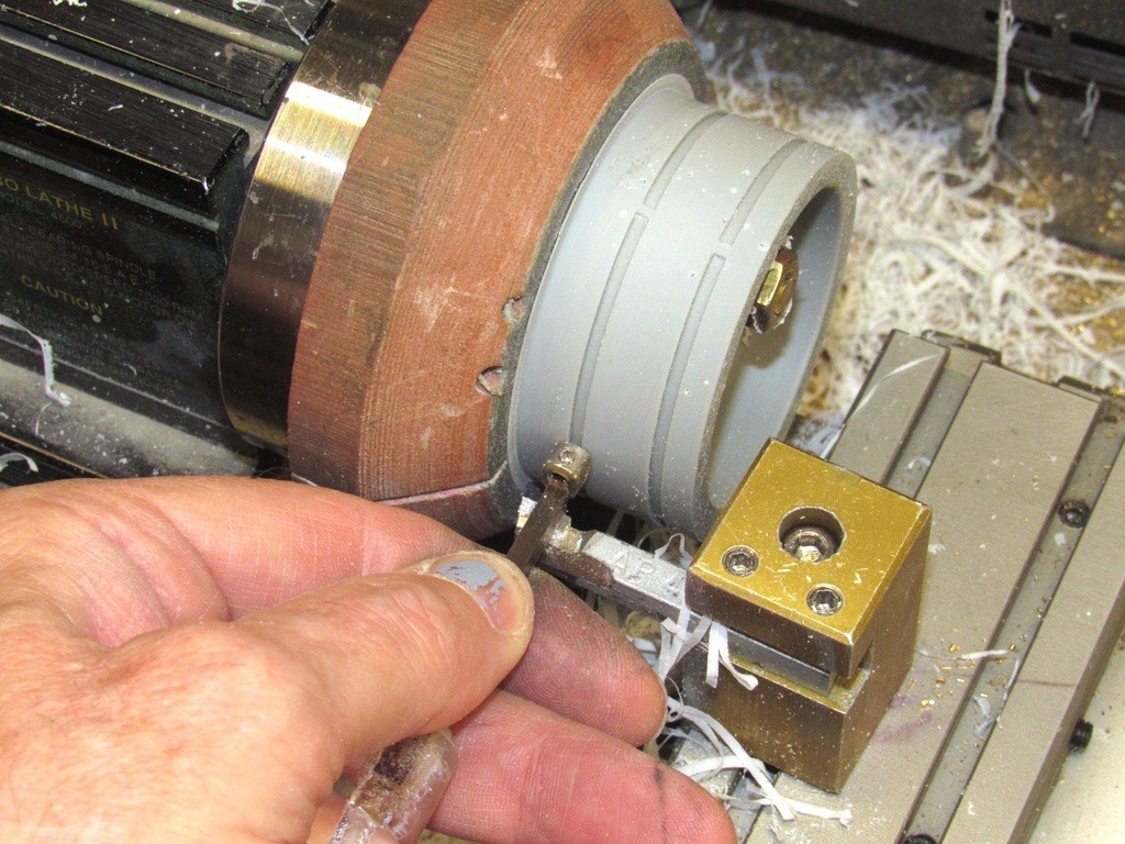
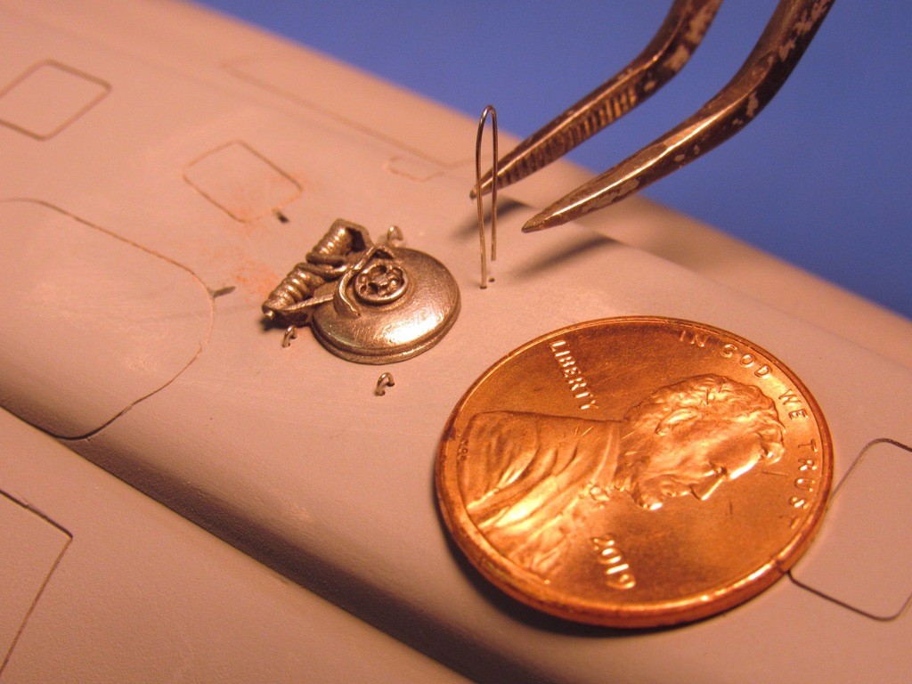
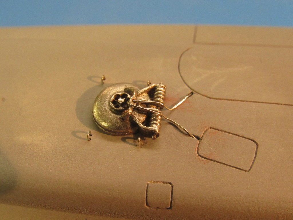
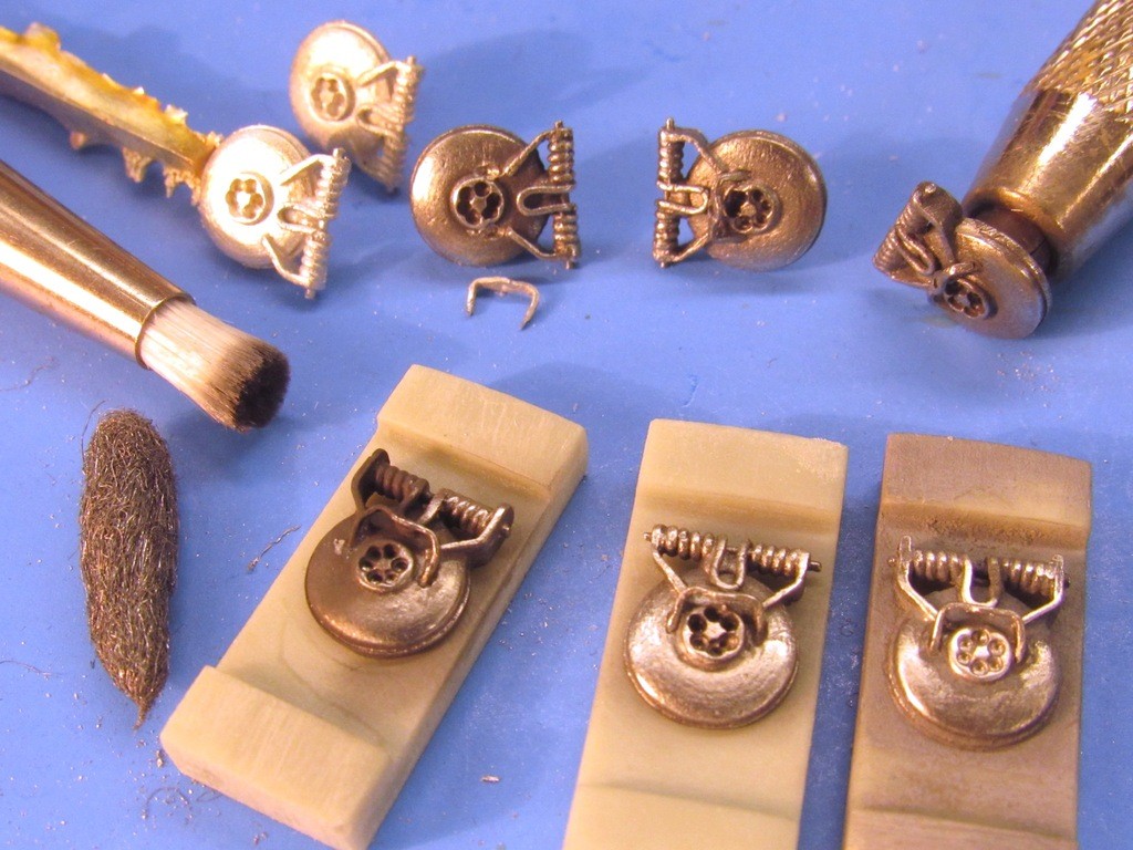
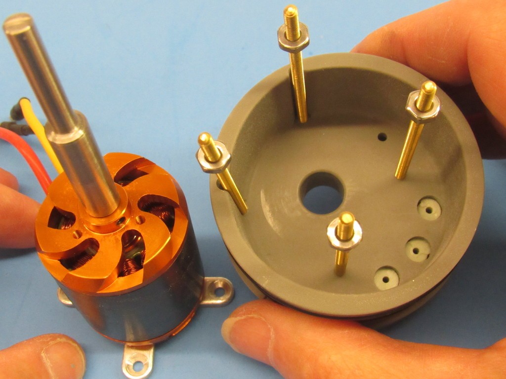
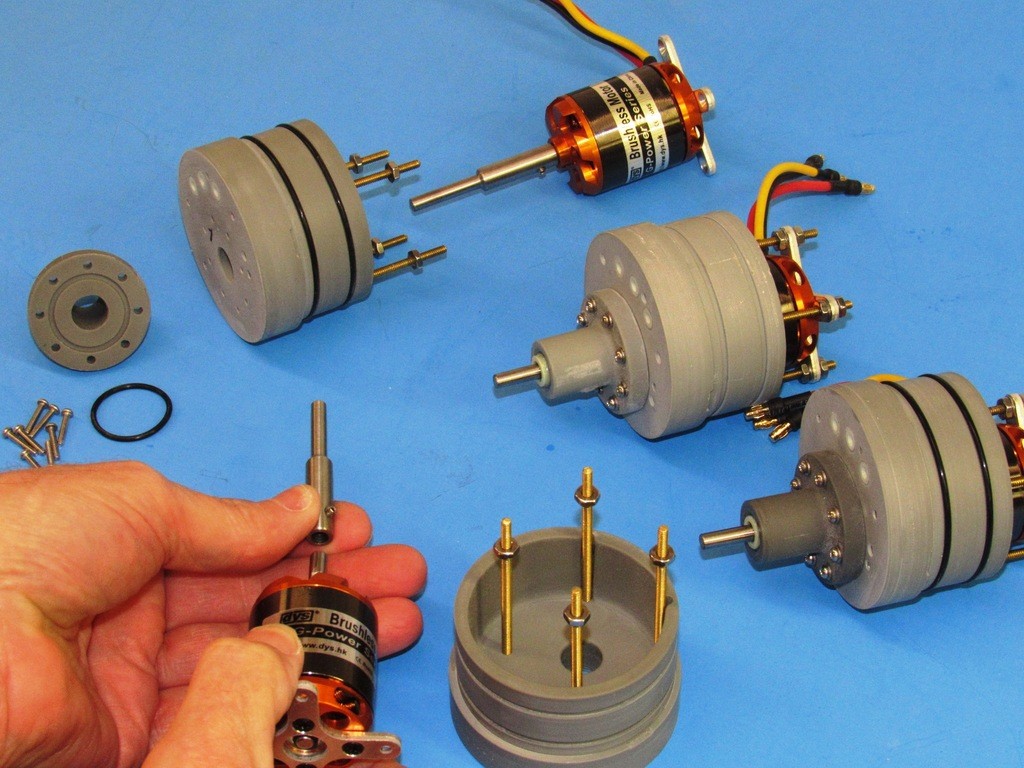
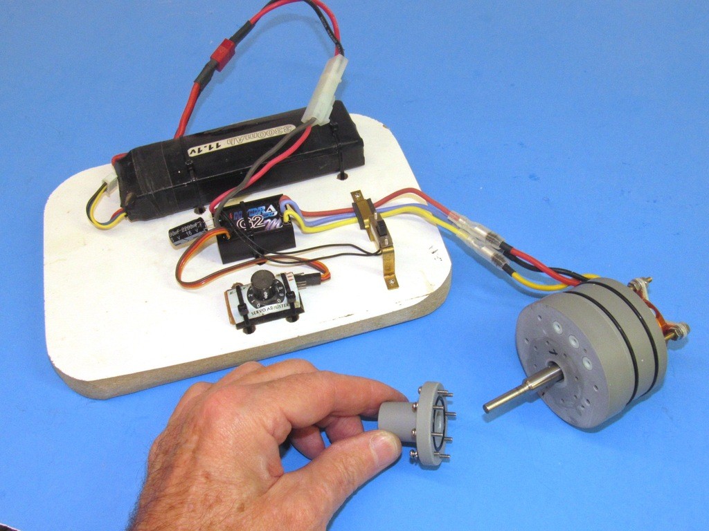
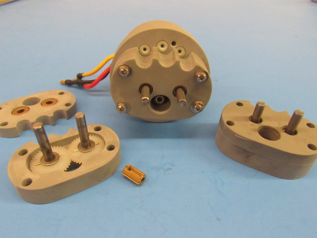
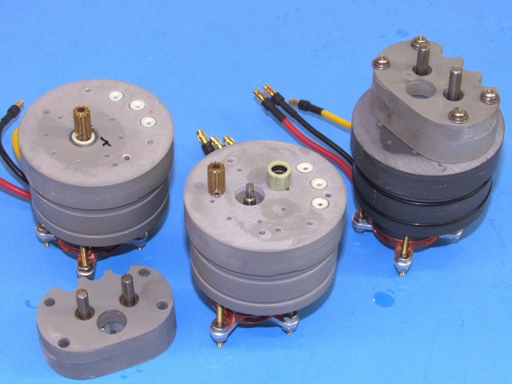
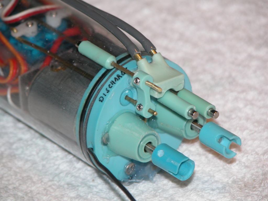
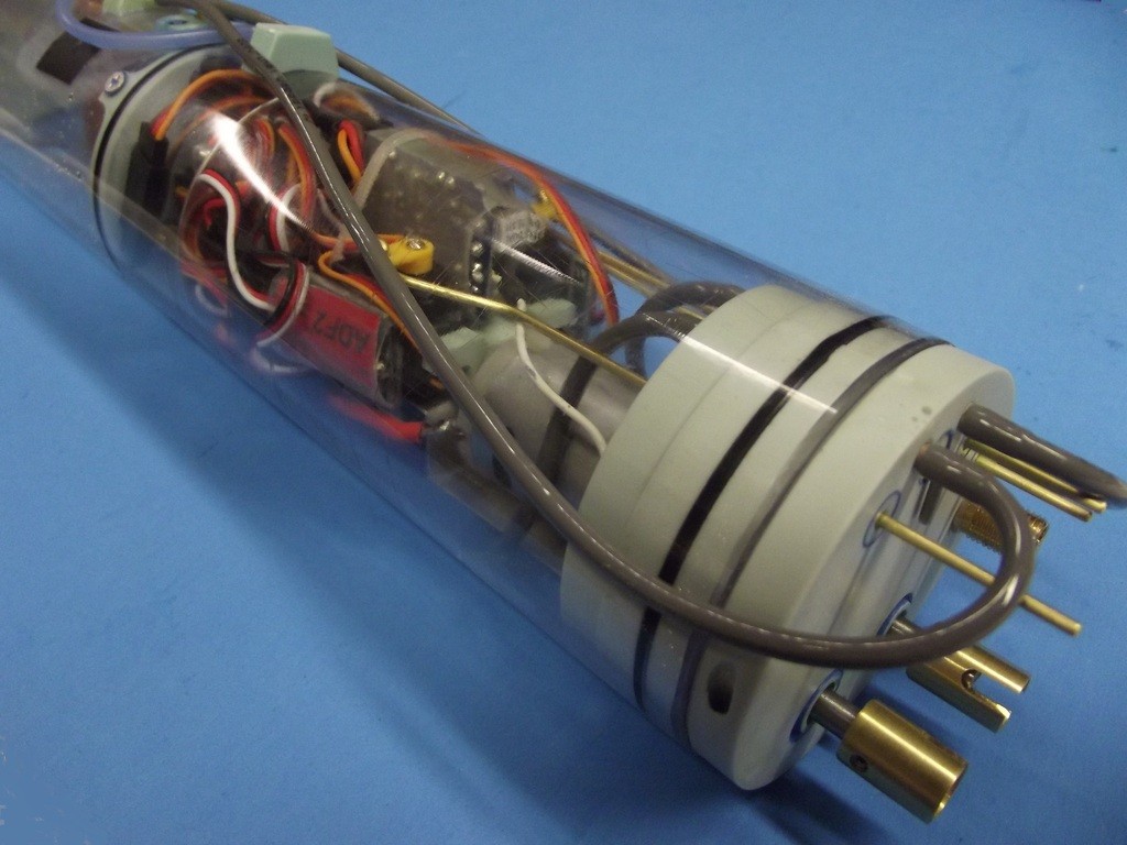
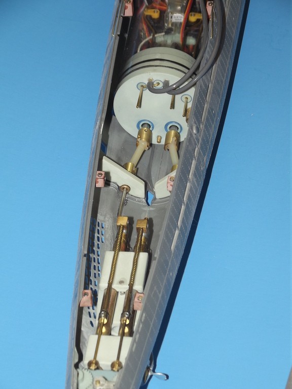
    I have yet to make the tool and cast parts for the optical, induction, and electronic items that top the masts that project atop the ALFA’s sail. What you are looking at are the brass masters that will eventually be used to make the rubber tools from which white-metal production parts will be cast.

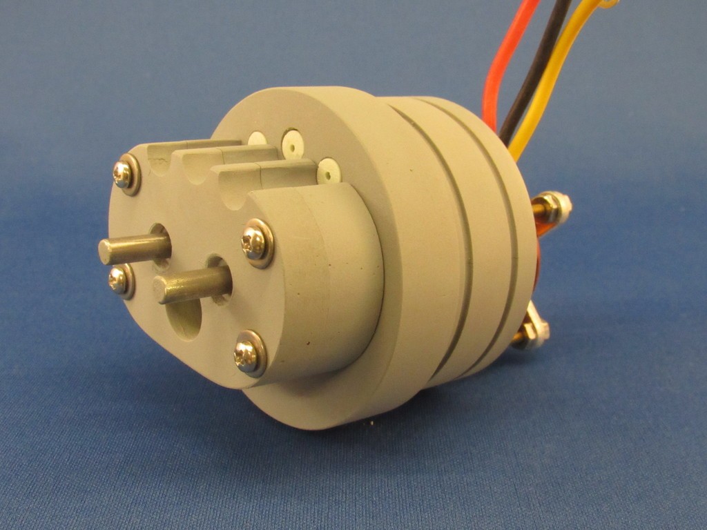
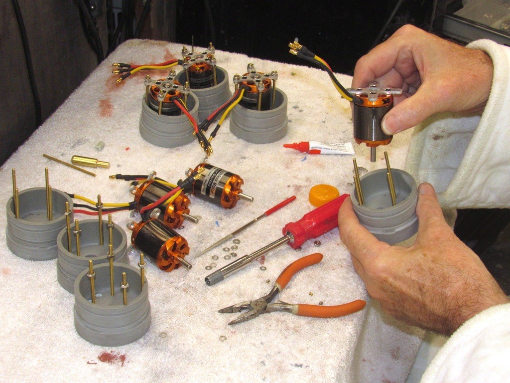
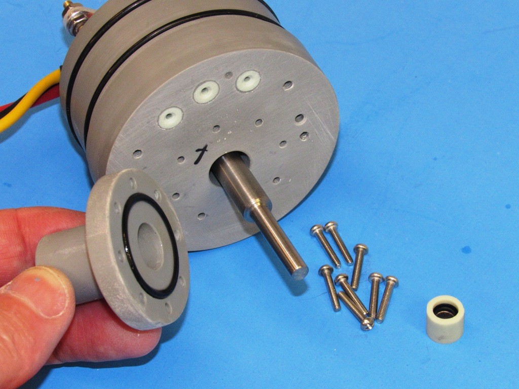
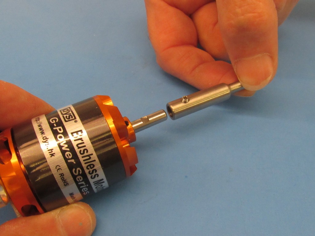
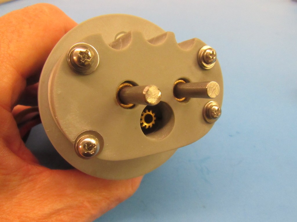
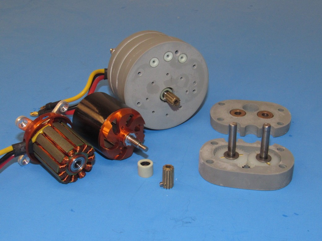
    What I’m handling in this shot is what I assume to be a combined snorkel induction head-valve-antenna mast – I have not been able to get a definitive answer as to the function of this mast, but that is my best guess. Anyway, it does demonstrate how the masts make a friction fit to the internal mast foundation piece.

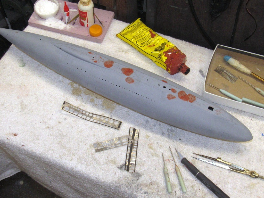
    An obvious cheat on my part is the non-scale representation of extended masts through closed fairing hatches. Though I’ve produced parts representing opened hatches I elected to simply poke holes through the centers of the engraved representation of those hatches through which the masts passed. Most of the time the operational model will only have the scope in place, the other masts left back on the table as I drive the model – the open holes serving a practical function: venting the free-flooding hull as the model submarine submerges and surfaces. All masts are in place only for display out of the water.

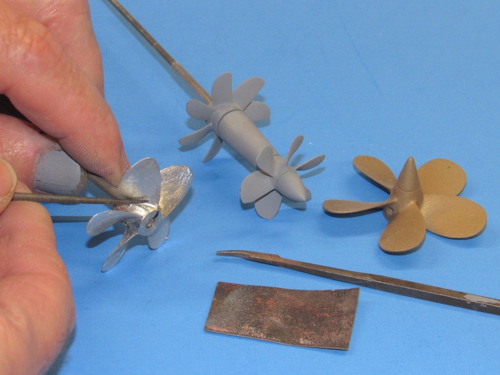
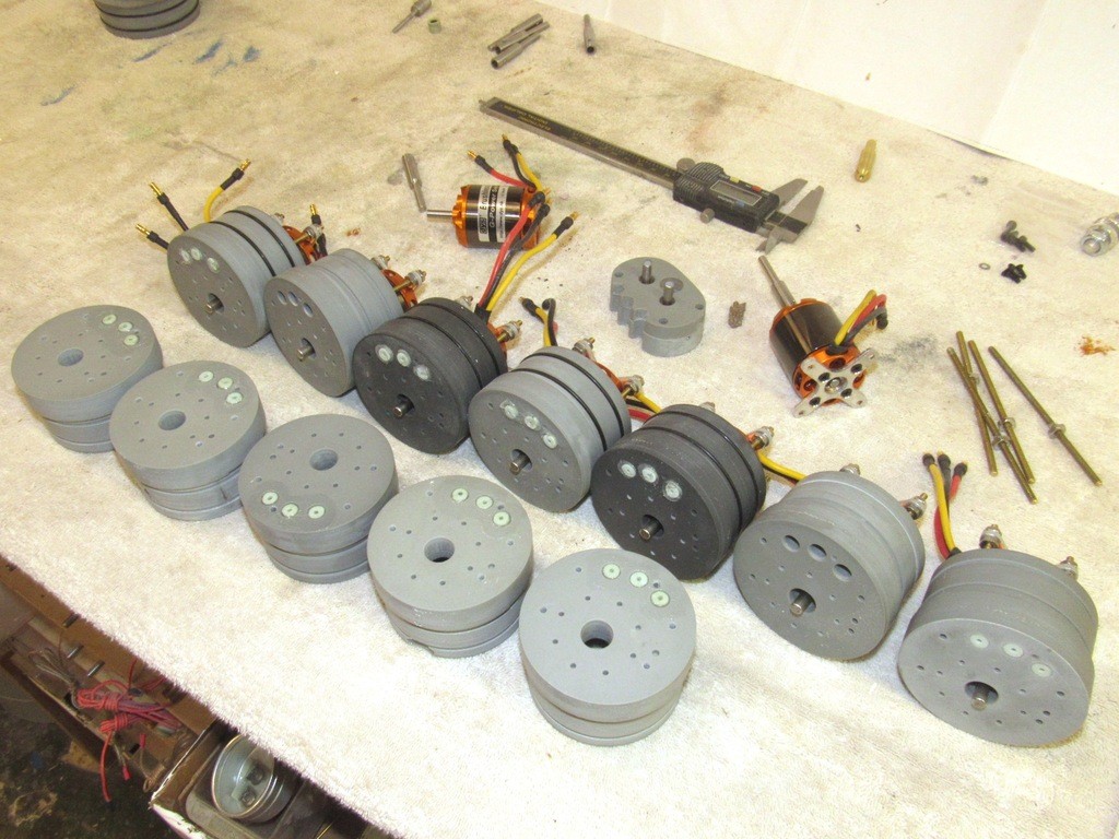
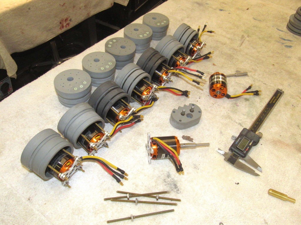
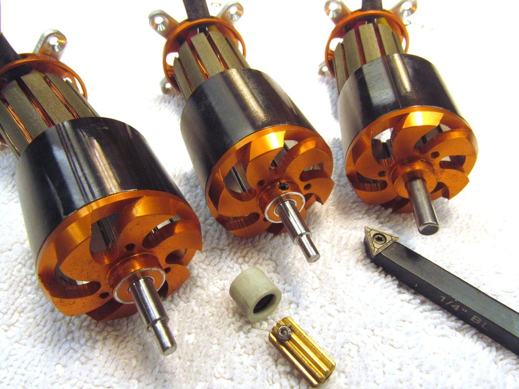
    Presented here are the ALFA, ALBACORE, and SCORPION propellers at various states of finish. From left to right: the ALFA propeller demonstrates the initial work needed to take a cast white-metal propeller from the raw state to a point where it’s ready for pickling. Here I’m filing back the invitable flash imparted to the casting from the tool.

    The two-propeller ALBACORE propulsor featured two concentric shafts, each swinging a counter-rotating propeller – identifying this as a phase-4 arrangement. The filing, pickling, and initial primer work has been done.
    The completed and painted SCORPION wheel shows the end-game of propeller manufacture.

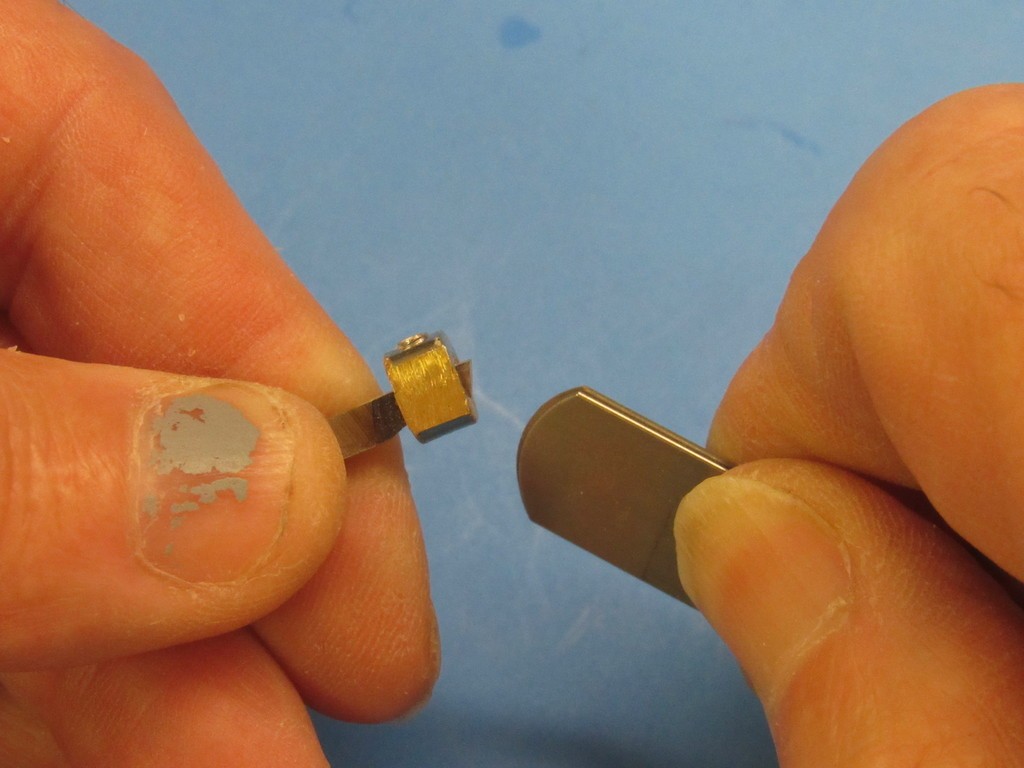
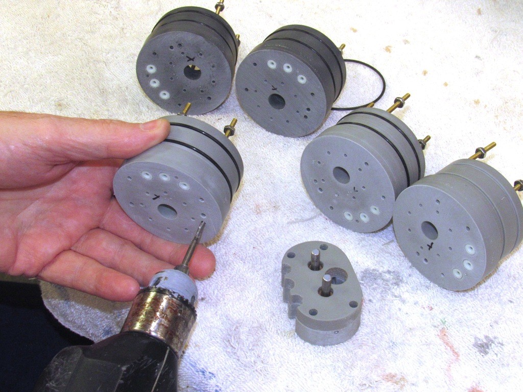
    Many non-ferrous metals tend to shrug off primer and paint if not first oxidized to pit the surface of the metal in order to secure a tight mechanical bond between surface and coating. The white-meal, (Tin-Antimony alloy) part is soaked in acid to oxidize its surface. The oxidation creates zillions of little pits that key with the coating applied over it. This ‘pickling’ process is simple: dunk the work in acid and while its immersed brush the surface of the part vigorously with (duh!) an acid-brush to insure complete oxidation of the parts surface, rinse in fresh water to get the pH back to normal, dry, and prime.

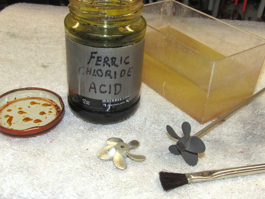
    Here, demonstrating the difference between a raw whit-metal casting and a worked and oxidized propeller. Once so pickled, the substrate is most receptive to the primer, producing a tight bond between metal and coating.
    Who is John Galt?

    Comment

    • trout
      Admiral
      • Jul 2011
      • 3545

      Instead od "today's work" this thread should be called "time in master class" or simply "master class".
      Thank you David for sharing. I will say it again, it takes time to make these postings. With stopping to photograph, downloading and photo touch up, to posting and coming up with the right amount of words to guide the reader along, it all takes time and away from the actual work. For what reason? Vanity? It could be vanity, I have seen some builders like that, but for David, I believe, it is to teach and share his knowledge. In IT (not exclusive to IT) you will hear a term knowledge transfer. It brings up a vision of a robot getting data or information uploaded into it for me, but it is a good image here to. It is a image of us getting information and then allowing us to process it to improve our performance. Anyways, must be the meds I am on causing me to expound like this, thank you for taking the time to share what you are doing. I hope that I can do you justice and be a better modeler from it.
      If you can cut, drill, saw, hit things and swear a lot, you're well on the way to building a working model sub.

      Comment

      • He Who Shall Not Be Named
        Moderator
        • Aug 2008
        • 12253

        Originally posted by trout
        Instead od "today's work" this thread should be called "time in master class" or simply "master class".
        Thank you David for sharing. I will say it again, it takes time to make these postings. With stopping to photograph, downloading and photo touch up, to posting and coming up with the right amount of words to guide the reader along, it all takes time and away from the actual work. For what reason? Vanity? It could be vanity, I have seen some builders like that, but for David, I believe, it is to teach and share his knowledge. In IT (not exclusive to IT) you will hear a term knowledge transfer. It brings up a vision of a robot getting data or information uploaded into it for me, but it is a good image here to. It is a image of us getting information and then allowing us to process it to improve our performance. Anyways, must be the meds I am on causing me to expound like this, thank you for taking the time to share what you are doing. I hope that I can do you justice and be a better modeler from it.
        With me, it's all vanity. This is, after all, 'performance Art'. Don't agree with Me? Then, why do we communicate our activity to others? No audience, no fun.

        As George Carlin put it: "Dig Me!!!!!"

        Like selfishness and self-involvement (even greed), vanity is a force that moves us forward. Selflessness is a waste of potential. The sacrificing meek wind up nailed to pieces of wood. The self-involved selfish types get things done.

        Problem is, we've permitted the compassion-police to sway too many of us to their level of meekness and un-accomplishment by branding positive traits as unseemly and 'bad' -- I won't have it!

        My world is black and white. The only gray in it is the primer I use. You either do, or you don't.

        I revel in my 'do', and scream my accomplishments from the mountain tops. I hold those who, by choice, 'do not' in utter contempt.

        Man lives to please himself (a tip of the hat to Ayn Rand).

        David
        Who is John Galt?

        Comment

        • trout
          Admiral
          • Jul 2011
          • 3545

          Oh, O.K., never mind.....
          If you can cut, drill, saw, hit things and swear a lot, you're well on the way to building a working model sub.

          Comment

          • He Who Shall Not Be Named
            Moderator
            • Aug 2008
            • 12253


            Last installment I presented the pretty side of model-building; kit assembly and the joyous and challenging tasks of scribing, detailing, and part integration.

            Well, this isn’t that!

            This installment I present to you the dark underbelly of professional model-making: dumb-ass, boring, repetitive, no-talent, soul-crushing production work.

            Exhibit-A: casting bulkheads and unions for our current line of Modular SubDrivers (MSD); a look at how raw resin parts are cast and machined into useful components that fit together into a rational system.

            Pictured here is about two-gallon worth of polyurethane casting resin in the solid state, fresh out of the rubber tools that gave them form. Note the attached sprues and risers hanging off of the castings.

            Casting resin parts goes like this: Rubber tools (molds), usually of the two-part type, are prepared; polyurethane resin is mixed with its hardener (catalyst), and quickly poured into the tool; the tool is placed in a pressure pot and subjected to at least one-atmosphere of pressure (14 psig) which is maintained until the liquid polymerizes, i.e. changes state to a solid; the tool is removed from the pot and opened up, and the part popped out; repeat till you crave death!


            I hate production work!

            Most of the MSD tooling is of the two-part type, the halves held together with rubber bands backed up by strongbacks – typically plywood or chip-board ‘shelving’ sock. But the tools are not assembled until their cavities and flange faces have been treated with a silicon part-release spray and a good dusting of talc or corn starch.


            My initial tooling for the MSD work was formed from masters that – as we found out after the first MSD’s were being evaluated – featured ‘stops’ that were too thin and, on the cast resin parts, would break easily when pried against, such as when attempting to pry a cylinder loose during disassembly. Instead of wasting the initial set of tooling after only a few shots (RTV rubber is expensive!)I elected to modify some of them by cutting away portions of the rubber, this resulting in castings with fatter stops. A crude solution, but one that worked well enough to justify the extra machining needed to true up the fatter stops.


            To slit the three different diameters of tools, I made three specific slitting tools; one for the 2.5” diameter union tools, one for the 3” diameter union tools, and another for the 3.75” diameter union tools. The work went surprisingly fast.


            The operation was simple enough: hold the semi-circular edge of the slitting tool in the existing grove of the tool, and rotate. Follow that with a 90-degree slit from the top with a hand-held X-Acto knife, and I’m done.

            Of note here is where the blade of this slitting tool is projecting – this cavity is both sprue and riser; it’s where the liquid resin is introduced into the molds cavity and were make-up resin comes from to make up any liquid lost as air-bubbles within the mix are crushed into solution during pressurization.


            I’ve poured several parts from these modified tools and I had no problem smoothing out the rough ‘stops’ on the lathe while turning the radial flanges to form tight fits to the Lexan cylinders they support. This is a stop-gap solution though; I’m re-working the masters with fattened stops and will produce ‘production tools’ that will incorporate that and other changes – to correct problems identified in the initial batch of MSD resin parts.


            Tool preparation starts with a heavy spray coating of part-release. This silicon oil forms a barrier between the tools rubber and the polyurethane casting resin. I go through the Mann 200 part-release by the case! Good stuff.

            Note the brass inserts in some of the tool halves. These ‘cores’ suspend an o-ring that will be encapsulated in the unions; that o-ring making a watertight seal between the unions internal bulkhead and brass tube conduit that runs the length of the ballast tank. After a casting is made, the tool is opened up and the part extracted, I then yank the brass core out which leaves the conduit bore and o-ring that slightly projects into that bore. Slick! I learned this trick by hanging around the rubber and mold shop aboard the USS YOSEMITY back when I was a snot-nosed Diver.


            To enhance the ability of the liquid casting resin to fill all voids within the tool a thick coating of talc or corn starch is applied within the tool cavities – the excess powder shaken out onto the floor before the tools are assembled. The powder coating held in place by the sticky part-release previously applied. The powder works to further isolate the rubber from the crazing effect of the casting resin, extending tool life. The powder also works to wick resin into the tight areas of the cavity, contributing to a better fill.

            Nowadays I can expect at least eighty cycles from a tool. Forty years ago I was lucky to get twenty. The marvels of modern chemistry.


            Artifacts of the resin casting process are the sprue and riser elements of the casting. These are the result of the cavities that introduce the resin to the tools cavities, permit the escape of displaced air, and provide make-up resin as entrapped air not vented away is crushed into solution during pressurization. These appendages to the casting proper have to be snipped or sawed off the resin part before any serious machining can begin.


            Some castings after clean-up and sizing are further worked with the installation of Oilite bearings, such as these ‘gear-splitters’ used to produce two counter-rotating shaft outputs from a single shaft input. Surprisingly CA adhesive works to permanently glue these oily flanged shaft bearings in place.


            Who is John Galt?

            Comment

            • He Who Shall Not Be Named
              Moderator
              • Aug 2008
              • 12253

              Exemplified here a motor-bulkhead casting has not only been equipped with a gear-splitter unit, but also shows off the post casting insertion of three watertight seals that pass control surface pushrods. You can just make out support studs, spider motor-mount, and out-runner type brushless motor that outputs into the gear-splitter through its own watertight seal.

              Casting MSD parts is only the start. There is much machining and part integration needed to make these parts useful elements of the system.

              As commercially available Lexan cylinder has a wide variance of diameters (very, very sloppy industry tolerance) -- I don’t know from buy to buy just what actual diameter I have in the racks -- I produce my bulkhead and union masters substantially over-sized in diameter. This not only accounts for the inevitable shrinkage of the room temperature vulcanizing (RTV) tool rubber and shrinkage of resin as it changes state from liquid to solid, it also assures that no matter how out of specification my Lexan cylinder is, I would be able to reduce the diameter of the cast resin bulkhead or union to fit to the cylinder at hand. One size DOES NOT fit all!

              In foreground is a raw cast resin union, mounted on a lathe holding fixture ready to be machined to the desired diameter. I’m holding a machined example of the same item, ready for insertion into the cylinder it has been sized to fit. The terribly flawed stop you see here, butted against the face of the holding fixture, is a consequence of the somewhat less than perfect slitting job I did on its tool to fatten up the stop in the eventual casting. Once faced and shaved to correct diameter the casting will be just like the one in hand.

              Shaving the outside diameter of the radial flange; as well as facing the god-awful ragged ‘stop’, is a simple lathe job. However, a big side-step away from ‘shop safety’ is the use of a hand-held cutting tool to gouge out the two o-ring grooves. The depth of the groove set to be about two-thirds the wall thickness of the o-ring used to make watertight the union between ah … the union and Lexan cylinder.

              Note how I use (most improperly) the lathes cross-slide mounted cutting bit as a tool-rest as I fine-tune, by hand, the depth of the o-ring grooves in this casting. Very bad shop practice to bare-fist a tool like this. No problem. It’s my frig’n shop, and I’ll do what I bloody well please, thank you very much!

              OSHA and the other Federal and local Regulatory agencies can kiss my nonunion ass!

              The o-ring groove cutting tool is simple enough, a tool-steel blank is mounted in an acrylic handle and its cutting edge ground and honed, and a modified wheel-collar used to act as a stop that insures the depth of o-ring groove cutting stops at the correct depth.

              A little math and I set the distance of the wheel-collar stop to the tip of the tool using the appropriate leafs of a feeler-gauge.

              The stop is secured to the tool with a set-screw.

              A cheat I employ if I find that the o-ring is either too tight or loose when the cylinder is installed over the union or bulkhead radial flange is to go to an under or over-sized o-ring. The end-game is to get a good mashing of the o-ring between flange and cylinder, easy to see through the transparent Lexan.

              Torpedoman A-School was not wasted on me!


              Who is John Galt?

              Comment

              • He Who Shall Not Be Named
                Moderator
                • Aug 2008
                • 12253


                I put in a few hours on the 1/96 ALBACORE and SCORPION models. The deck hatches – hatches that are pretty much of the same type for these boats – were worked up in mass to limit the steps taken to get them ready for installation. The two deck hatches on the SCORPION are recessed and faired over by fairing plates which feature an opening in their centers to clear the hatch hand-wheel and fairing bail. The bail fairleads the escape buoy down-haul cable when it’s deployed.

                The ALBACOR deck hatch arrangement is a bit different: the forward hatch (on later variants of the much altered little research boat) is recessed and faired over like the SCORPION’s, but the after deck hatch sits atop the hull, which makes for an interesting and eye-catching arrangement. Note the opening near the ALBACORE’s bow what will later contain the bow compartment deck hatch. A fairing plate will fit the opening.


                In the early days of American ‘modern’ submarines the escape trunks (typically two of them, one forward over the torpedo-room/bow compartment; and one back in the engineering spaces) were topped with the hardware needed to make possible use of the McCain rescue chamber. A down-haul cable, released by the submarine, and yanked to the surface by a buoy, would be spliced into a winch within the rescue chamber (an underwater elevator, if you will) and used to pull the rescue chamber down onto the seat surrounding the escape trunk hatch. Four hold-down padeyes on the submarines deck would be made up to fixtures within the skirt of the escape chamber to more securely attach the rescue chamber to the deck of the disabled submarine.

                Here I’m fitting small gauge wire into holes drilled around the ALBACORE’s deck-level after hatch, these forming the rescue chamber hold-down padeyes. The diminutive size of the 1/96 hatch and other items emphasized by the penny.


                The down-haul cable runs from a reel under the submarines deck, fairleads through the hatch ‘bail’ and then runs to the escape buoy. When deployed the cable end, with a swaged flair fitting at its end, jams into the bottom of the bail, positioning the vertically running down-haul cable dead-center to the hatch – insuring that the rescue chamber will naturally seat neatly around the hatch and hold-down padeyes when its skirt makes contact with the submarines deck.


                I make it a practice to insure all off-model items are test fitted to insure I won’t have any assembly problems after everything has been painted. An example of that precautionary work is the after deck hatch of the ALBACORE model. The hatch, rescue chamber hold-down padeyes, and down-haul cable all assembled as they eventually will be on the finished model. Once I affirm that everything fits properly, the items are taken off the model and finished separately. Rejoined only after all painting and weathering is completed.


                The recessed deck hatches are mounted on cast resin foundations that will eventually be glued to the inside of the hull, with the top of the deck hatch projecting through a hole in the center of the deck fairing plate. These are cast white-metal items. Note that the hatch and fairing bail are separate items that have to be glued together. Two recessed deck hatches for the SCORPION and one for the ALBACORE; and one deck mounted hatch for the ALBACORE.


                Work continues on the Modular SubDriver motor-bulkheads. The motor bulkhead can be configured for either single or dual-shaft output.


                The out-runner type motors required four supporting studs to reach forward and make up to the ‘spider’ type motor-mount. A bit convoluted, but necessitated by the need to clear the rotating motor body from the motor-bulkhead.


                Who is John Galt?

                Comment

                • He Who Shall Not Be Named
                  Moderator
                  • Aug 2008
                  • 12253

                  How did that Monk get in the shop!?…

                  No dress-code here!

                  An alternative arrangement to the motor-bulkhead is to attach a ‘gear-splitter’ that converts the single-motor output to two counter-rotating outputs. Here I’m tapping the holes that will accept the gear-splitter mounting screws.

                  I usually do my brain-storming on paper through sketching. If it doesn’t work in two-dimensions, sure as **** it won’t work in three! Here I’m working out an intermediate coupler between motor shaft and output shaft to the model submarines propeller. The key design criterion is the need to pass this intermediate coupler through a watertight seal.

                  This is the arrangement for a single-shaft output from the motor-bulkhead.

                  Who is John Galt?

                  Comment

                  • He Who Shall Not Be Named
                    Moderator
                    • Aug 2008
                    • 12253


                    Who is John Galt?

                    Comment

                    • george
                      Captain
                      • Dec 2010
                      • 727

                      Can you tell us where you get the two gears and spur gear for the dual output drive? Could you also tell us their part numbers? Are those gears factory fitted with shafts OR done by you later?
                      Thanks for ALL your lessons here.
                      So much rereading and trying to remember.
                      Thanks for you taking the time to post this.
                      George

                      Comment

                      • He Who Shall Not Be Named
                        Moderator
                        • Aug 2008
                        • 12253

                        Originally posted by george
                        Can you tell us where you get the two gears and spur gear for the dual output drive? Could you also tell us their part numbers? Are those gears factory fitted with shafts OR done by you later?
                        Thanks for ALL your lessons here.
                        So much rereading and trying to remember.
                        Thanks for you taking the time to post this.
                        George
                        I get the 36-tooth spur gear from Stock Drive. I have the brass pinion gear made, in two, three-foot lengths, for about three-hundred bucks -- special order.


                        David
                        Who is John Galt?

                        Comment

                        • george
                          Captain
                          • Dec 2010
                          • 727

                          Hello again
                          Thanks for the gear source, my mistake I should have added that I am using a brushed motor for my 1/72 Revel Type VII and IX. Would the brass spur gear be overkill becuase I have No plans on usung a brushed motor. What, from where could be used in it`s place with the plastic gears?

                          Thanks again
                          George

                          Comment

                          • He Who Shall Not Be Named
                            Moderator
                            • Aug 2008
                            • 12253

                            Originally posted by george
                            Hello again
                            Thanks for the gear source, my mistake I should have added that I am using a brushed motor for my 1/72 Revel Type VII and IX. Would the brass spur gear be overkill becuase I have No plans on usung a brushed motor. What, from where could be used in it`s place with the plastic gears?

                            Thanks again
                            George
                            I use direct drive brushed motors on my 1/72 Type-7.


                            And a single brushed motor driving a gear-splitter to produce two, counter-rotating output shafts for the Type-9.


                            David
                            Last edited by He Who Shall Not Be Named; 02-21-2020, 01:29 AM.
                            Who is John Galt?

                            Comment

                            • HardRock
                              Vice Admiral
                              • Mar 2013
                              • 1609

                              "The down-haul cable runs from a reel under the submarines deck, fairleads through the hatch ‘bail’ and then runs to the escape buoy. When deployed the cable end, with a swaged flair fitting at its end, jams into the bottom of the bail, positioning the vertically running down-haul cable dead-center to the hatch – insuring that the rescue chamber will naturally seat neatly around the hatch and hold-down padeyes when its skirt makes contact with the submarines deck."

                              I have to ask this; How long was the cable?

                              Comment

                              • He Who Shall Not Be Named
                                Moderator
                                • Aug 2008
                                • 12253

                                Originally posted by HardRock
                                "The down-haul cable runs from a reel under the submarines deck, fairleads through the hatch ‘bail’ and then runs to the escape buoy. When deployed the cable end, with a swaged flair fitting at its end, jams into the bottom of the bail, positioning the vertically running down-haul cable dead-center to the hatch – insuring that the rescue chamber will naturally seat neatly around the hatch and hold-down padeyes when its skirt makes contact with the submarines deck."

                                I have to ask this; How long was the cable?
                                I don't know. Considerably less than the design-depth of the boat, that's for sure. Somehow 300-feet keeps popping into my head.

                                The McCain rescue chamber was only good if you got stuck this side of the continental shelf -- even so, most of that is below crush-depth. We often quipped that the system was to comfort the folk back home and was useless if you grounded anywhere on patrol. The later DSRV kinda fixed that issue. Interestingly that system was certified to operate deeper than the boats of that time could survive. Submarine rescue of personnel in deep water is a fairy-tale (but the MIKE incident put the lie to that glib statement).

                                David
                                Who is John Galt?

                                Comment

                                Working...