the SubDriver becomes modular

Collapse
X
 
  • Time
  • Show
Clear All
new posts
  • MFR1964
    Detail Nut of the First Order
    • Sep 2010
    • 1290

    #46
    Always a pleasure to annoy you David, i'm fine, goofing around on this ball of dirt, and running around in the cave.
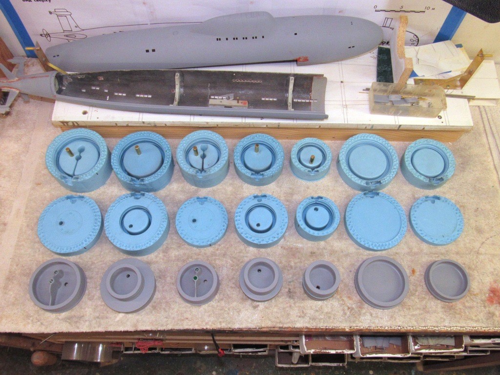
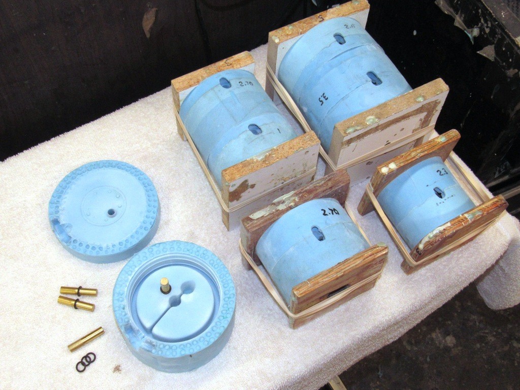
    Nice solution the modular style, so, WIP V80??, it should be cured by this time.

    Manfred.
    I went underground

    Comment

    • He Who Shall Not Be Named
      Moderator
      • Aug 2008
      • 12255

      #47


      Before the mid-day break for my hideous nap I got this much done converting a 2.5"-to-2.5" pre-production union casting into a 2.5"-to-3" union. I turned a new RenShape radial flange for the step-up required, using the core of a ballast tank half of a 2.5" union for the innards of this pre-production master.

      Anyway, here's how far I got this morning:


      Later I'll produce a step-up union for a larger, 3.75" cylinder.

      David
      Who is John Galt?

      Comment

      • He Who Shall Not Be Named
        Moderator
        • Aug 2008
        • 12255

        #48

        It’s one thing to come up with a clever innovation on an old concept – maturing the WTC to a proper modular system being discussed here as example – but it’s another thing to knuckle-down and get on with the donkey-work of actually making the items that will comprise the new system.

        You’re looking at about two-hundred-dollars worth of 2” thick, 40 lbs. per-cubic-foot, pattern making medium. Most of it soon to be reduced to chips on the shop floor. God’s answer to pattern makers, this extremely dense polyurethane foam is so much superior to the Kiln-dried, carefully selected pattern maker woods used almost exclusively a half-century ago. Sugar Pine was my favorite, but all that timber has long been pulled from the bins, completely replaced by the synthetics. Thank you chemical-scientists!

        No grain. No pitch. No drying and cracking over time. RenShape takes to all adhesives, and its high pH sets off CA glue in record time. If RenShape could only cook!

        Here’s the one I prefer for most of my detail work (the less dense stuff requires extensive filling to get a good surface finish, so I use that version only as floatation material or a back-up to a GRP skin).

        https://www.freemansupply.com/produc...modeling-board.

        ‘Measure twice and cut once’, as the old Carpenter’s saying goes. And that double-check philosophy starts with a carefully prepared set of orthographic shop drawings, to the scale of the work, and oversized to account for tool and casting shrinkage (that fudge-factor more art than math, I can assure you!).


        I had already made a master, a tool, and some castings of the 2.5” ballast tank half of the 2.5-to-2.5 union. Now has come the time to make like units for the 3” and 3.75” ballast tank union halves. To save myself effort I simply took the core of the 2.5” castings and married them with 3” and a 3.75” radial flange. To ready these cores I milled away the 2.5” radial flanges on the mill as seen here.


        Flat bottom work is easily secured to the milling machines cross-feed bed with a simple L-section aluminum strong-back held down with two jacking screws – holding fixture 101. To enhance the friction between work and bed I glued a big piece of sandpaper atop the bed.

        I’m grinding away the radial flange of the original 2.5” diameter after union half. That work has already been done, as seen with the milled union half to the left. The objective is to insert these cores into larger diameter, RenShape radial flanges. One is for the 3” diameter ballast tank. The other is for the 3.75” diameter ballast tank.


        Here I’m turning a larger diameter radial flange on the lathe. I’m holding a core that will insert within the radial flange, that core containing the foundations and pass-through holes needed to operate the vent valve and (if installed) emergency blow valve.


        This is the end-game for the two ballast mechanism cores: use them as inserts into the larger diameter radial flanges.

        Important safety note: only idiots ware long-sleeve shirt, ties, apron strings tied at the front, and gloves around powerful rotating machine tools! First lesson in shop-class: “Machines don’t care” and, “Machines cut metal and flesh with equal enthusiasm!”

        Yes, sometimes I’m a careless idiot. And sometimes … I pay the price, and got the scars to prove it! Not battle-scars. No! Idiot scars.

        MACHINES DON’T CARE!

        Want some reinforcement? Check out this video (have a puke-bucket handy), https://youtu.be/lxD7f2zCG40


        RenShape is easy to cut but quickly dulls high-speed steel. I found it more expedient to do the rough-cuts on the mill and to finish off the round-work on the lathe. Typically a blank was turned to the outside diameter on the lathe then transferred to the mill and the internal cavity roughed out.

        Notice the Michael Jackson glove-look (I was getting blisters from spending two days driving cross-slides, that is why I’m warring the damned thing).

        STUPID!

        Every time I look at the pictures of me operating heavy rotating machinery like this I cringe! (In the caring, and caressing voice of Escape From New York’s villain, A-number-One, as shop-class instructor: “WHAT DID I TEACH YOU!!!!”).

        God-damned! Sometimes I’m such a stupid dumb-ass!! And after seven-decades I still have all my fingers! Amazing.


        Who is John Galt?

        Comment

        • Scott T
          Commander
          • May 2009
          • 378

          #49
          Question on renshape. Is a super glued joint strong enough to turn? If yes could you then cut the cylinder with a bandsaw then glue it to a solid renshape plate then finish turning?
          Work is looking good.

          Comment

          • He Who Shall Not Be Named
            Moderator
            • Aug 2008
            • 12255

            #50
            Originally posted by Scott T
            Question on renshape. Is a super glued joint strong enough to turn? If yes could you then cut the cylinder with a bandsaw then glue it to a solid renshape plate then finish turning?
            Work is looking good.
            I'm not clear on this. Am I turning a RenShape cylinder or a Lexan cylinder, Scott? I face-mount RenShape to a RenShape face-plate all the time without incident. The CA bond is iron strong with that material.

            David
            Who is John Galt?

            Comment

            • Scott T
              Commander
              • May 2009
              • 378

              #51
              So I see you milling out the inside portion of the end-cap/ballast tank and
              wondered if it would be less labor intensive to cut, glue then turn/mill the part.

              A good shop teacher always tells you afterward what is easier.

              Click image for larger version  Name:	cutting.jpg Views:	0 Size:	87.4 KB ID:	134825

              Comment

              • He Who Shall Not Be Named
                Moderator
                • Aug 2008
                • 12255

                #52

                Before I once again get bogged down in the minutia of union and bulkhead pattern and tool making, let me remind you of the objective here:

                The creation of a sub-system of various unions and bulkheads that permits the quick, easy, and fastener-free means of assembling different diameters of Lexan cylinder to form a single, purpose built Modularized SubDriver – a MSD suited for a specific shape of r/c submarine hull with a ballast sub-system sized for that particular model. If the positive features of the modularized SD do not strike you immediately, I will later summarize them for you.

                Examine the photo below. It illustrates the basic differences between the old, constant diameter SD with its many fasteners and sloppy external SAS plumbing; and the new modularized SD showing off the fastener free unions between different diameter Lexan cylinders, varied diameters, and no external plumbing.

                And now, back to the shop!


                Most the gross grinding away of RenShape, as I worked the masters, was done on the milling machine. Once I pulled the work out of that nasty Machinist’s version of a wood-chipper I transferred the work to the lathe to finish shaping. Note the use of a simple aluminum L-section strong-back and all-thread jacking screws to hold the work down tight on the mills bed. KISS.

                I’m not at all shy about drilling and taping holes, welding, or bolting things onto the bed, foundation, spindle, or drip-pan of my machine tools if doing so serves my needs; hand and machine tools can and will be modified to adapt them to my specific wants. I run the show here. Not Dremel, Black & Decker, Chicago Machine or Vigor.
                Secure from rant.


                The union and bulkhead masters nearly completed. I still have to insert the forward union ballast mechanisms into the RenShape 3-inch and 3.75-inch radial flanges.

                Some of the abrasives used to improve the finish of the masters on display here. Bondo was used to fillet the ballast mechanisms inserts and radial flanges.

                In background is a 2.5-2.5 MSD, showing that a constant diameter SD is still possible if the right union is employed between the after dry space and ballast tank cylinders.


                The union and bulkhead masters were given a thin coating of West System epoxy laminating resin. I cut the catalyzed resin a bit with lacquer thinner to make it flow on a bit easier with a brush. The work was left to cure hard for twelve-hours.


                At this point the 3 and 3.75-inch diameter forward union halves received their ballast mechanism innards which were CA’ed in place. I poured on catalyzed epoxy to fillet between inserts and the large radial flanges. Another twelve hours for that to cure hard, then all masters were wet-sanded with various #400 grit sanding tools to rough up the surfaces to insure good bonding of the first primer coat.

                The masters were given three coats of primer, sanding between each. They were then mounted on molding boards, containment damns erected, and the first half of the RTV silicon rubber tools poured.


                Here I’m pouring the second half of the rubber tools that will be used to produce cast resin union and bulkhead parts.


                Each union type (ballast equipped and basic) and bulkhead had its own dedicated two-piece rubber tool. The masters used to create these tools are in foreground. Note the 11/32” brass rod cores inserted into those unions that would receive an o-ring which would later make watertight the conduit that would run the length of the ballast tank.


                It’s not enough to provide just a simple sprue hole (the path the resin takes from mixing cup to interior cavity of the tool) when dealing with a tool that takes a significant amount of resin to fill it. A ‘riser’, a reservoir if you will, is incorporated in the sprue to provide make-up resin to back-fill the cavity as entrapped air-bubbles are crushed during pressurization.

                In these tools I provide a riser right under the sprue hole. First, I cut out the riser cavity in one halve of the two-part tool; mark the edges of the riser cavity with black oil-paint, mash the second half of the tool in place to pick up the paint, which indicates the shape of the riser; and cut out the riser cavity into the second half of the tool.


                Each tool is sandwiched between two wooden strongbacks and the assembly compressed together with rubber bands. Sometimes I gang two or more tools together between a set of strongbacks. This is how the tool halves are pressed together as I pour in catalyzed resin into the sprue hole. Note that each tool has marked on its surface the weight, in ounces, of resin it holds. This goes a long way in minimizing the amount of resin wasted after a pour.

                Before the first pour in a tools life I get a close approximation of the weight of resin required through a simple conversion: I weigh the master, multiply by 1.5, and that gives me the weight of resin required to fill the tools cavity. As you can see, RenShape -- the 40 lbs. per cubic foot stuff -- is a bit less dense than resin.

                Detailed to the left in the below photograph shows how I encapsulate the conduit sealing o-ring within the union/bulkhead. The removable brass rod suspends the o-ring within the tools cavity during the pour. After the resin changes state, the tool is pulled apart, and the rod removed, leaving the embedded o-ring and a bore that will pass the ballast tanks 11/32”o.d. brass conduit tube. The conduit maintains watertight integrity between the forward battery space and the after dry space and while doing so passes the power and other leads between the two dry spaces.


                Polyurethane casting resin is mixed up, poured into the tool(s) and the work is placed into a pressure pot which is pressurized to about 15 psig for the time it takes the resin to change state from a liquid to a solid. Typical in-pot time for relatively thick parts like these is about twenty-minutes. The thicker the cross-section of the tools cavity, the more heat generated during the cure, the faster the state change.

                Last edited by He Who Shall Not Be Named; 11-26-2019, 12:33 PM.
                Who is John Galt?

                Comment

                • He Who Shall Not Be Named
                  Moderator
                  • Aug 2008
                  • 12255

                  #53
                  The pot is de-pressurized, the work taken out, the tools opened and the cast resin parts extracted.

                  Note the brass rod core piece projecting from the cast part. In its center – now encapsulated within the resin part – is the conduit sealing o-ring. When the core is pulled, it leaves the o-ring and a bore that will later accept the conduit that runs the length of the MSD’s ballast tank.
                  Who is John Galt?

                  Comment

                  • He Who Shall Not Be Named
                    Moderator
                    • Aug 2008
                    • 12255

                    #54

                    Old and new r/c submarine operating systems on display here. Each type embodies the means of control, propulsion, and ballast water management needed to make a scale model submarine work in a credible and reliable manner.

                    The system on top is the old, single cylinder type SubDriver (SD). The two bulkheads that divided the cylinder into three spaces are fixed in place with machine screws -- screw holes that sometimes resulted in cracks that would migrate over the seals causing water leaks into the dry spaces. And this type SD compelled me to select one diameter size cylinder for the entire length of the SD, this often not the ideal utilization of annular space between it and the interior of the model submarines hull. And the single cylinder system had just too many hoses and manifolds sitting proud of the cylinder, all potential points of failure.

                    Many of the SD shortcomings have been eliminated with the next step up the evolutionary ladder: the Modular SubDriver (MSD), seen at the bottom of the picture.

                    No mechanical fasteners to hold bulkheads in place. Instead, only O-ring friction holds three separate lengths of Lexan cylinder in place -- this innovation making access for repair, maintenance, and adjustment a much easier task. As an added benefit the MSD’s ballast water management sub-system has been consolidated into a tight, accessible package, eliminating most of the external plumbing which plagued the original SubDriver design.


                    The MSD contains the same devices as the earlier SD but does it within an envelope that can quickly and easily be changed in length and diameter to suit a specific application. As exemplified with this tear-drop shaped hull the arrangement of the three separate cylinders has been selected to make maximum use of the available space within this free-flooding model submarine model.

                    With few exceptions an r/c submarine makes use of the traditional devices as other r/c controlled vehicles. However, only air-ships and submarines require a means of changing the vehicles displacement within the fluid it operates; and only a submarine requires an assured means of autonomously sensing and correcting its pitch angle. The main destinguishing burden an r/c submarine has over all other vehicle types is the need to keep things dry at all times.


                    There are many ways to move water in and out of the ballast tank if the intent is to change the submarines displacement by taking on an amount of water weight equal to the weight of water the above waterline structures displace when immersed.

                    My SemiASperated (SAS) ballast water management sub-system pushes the water out of the ballast tank by displacing it with air. Air either scavenged from within the dry spaces of the system or from atmosphere. Pictured is an old SubDriver system employing the SAS cycle -- a Rube Goldberg delight, to be sure.


                    This better illustrates the SAS ballast sub-system.

                    A vent valve atop the ballast tank (not shown) opens, venting the air from within the ballast tank, allowing water to fill the tank and the submarine is totally under water. The formerly above waterline portions of the submarine, now fully immersed in water, produces a buoyant force equal to, but opposed to, the weight of the ballast water taken on. The boat assumes the state of ‘neutral buoyancy’.

                    To surface the water in the ballast tank is blown out with air compressed by the LPB. Air is initially scavenged from within the SubDrivers interior (the snorkel valve is closed). Once the sail broaches air is taken from atmosphere.

                    Internal air is only good for a partial blow of the ballast tank, but it’s enough to broach the sail above the surface. Once the snorkel head-valve opens the partial vacuum created within the dry spaces is back-filled with surface air and the blow continues with air from the surface.


                    Two-valve protection is an almost religious tenant within the submarine community – you always want a back-up stop to any line subjected to sea pressure. That philosophy has carried over to my model submarines as well. The ‘safety float-valve’ is the back-up valve within the induction side of the SAS ballast sub-system. The primary stop to water ingress to the induction line is the snorkel head-valve up within the sail. The safety float-valve is the backup, it prevents any water that gets past the snorkel from leaking into the SubDrivers dry spaces – it only closes if there is water in the line, otherwise it passes air going in or out of the systems dry spaces.

                    Here I’m testing a unit by injecting first air, then water. It must pass the air, but immediately block the flow of water.


                    ]
                    Who is John Galt?

                    Comment

                    • He Who Shall Not Be Named
                      Moderator
                      • Aug 2008
                      • 12255

                      #55
                      Within the safety float-valve a float, with a rubber disc atop it and a weight within it will remain clear of the air passage between the nipple at the bottom and the nipple at the top of the device. However, should water get into the safety float-valve, the passage is blocked, keeping water from getting into the dry space of the SD/MSD.

                      The body of the safety float-valve is formed from a short length of copper pipe and two copper caps. The lower cap is permanently soldered in place; the top cap is removable for servicing and is secured and made watertight with RTV adhesive. Here I’m cleaning parts for soldering. The end-game: I’m holding a completed, ready-for-issue unit.

                      The air-pump used to discharge the ballast water is this small diaphragm pump, modified to make it suitable for handling water as well as air – if, and when, water gets into the induction line (and it will!!) I don’t want any of it to get out of the pump and into the dry spaces of the SD/MSD. The elastic elements of a diaphragm pump prevent ‘water hammering’ of the mechanism should it encounter a non-compressible fluid. Though technically described as positive displacement type pumps, because of their slight ‘give’, the diaphragm type will move water or air with great enthusiasm and without hammering itself to death.

                      Each pump -- I revert to submarine-speak and call them Low Pressure Blowers (LPB) – had its rubber seal, which isolates the pump workings from the pumps surroundings, mashed tighter within its housing through a few modifications of the assembly. This work to insure no water leakage past the pump body and into the dry space.

                      Each modified LPB was then subjected to about 15 psig of water pressure at the discharge and induction sides of the pump and the pump body examined for water leakage past the seal.

                      Once a LPB had passed its leak-check it was then outfitted with two spark-suppression .01 micro Farad capacitors. Electronic ‘noise’ within the tight confines of an r/c vehicle has to be avoided; spark-suppression of brushed motors and switches is a necessity.

                      Final check of the LPB’s was to spin the motor under load (dead-header test), followed by an affirmation of correct discharge rate. At this point I declare the units, ready for issue.

                      The new MSD design has greatly streamlined the integration of the SAS elements. Here you see a typical MSD ‘after ballast tank bulkhead’, or ‘union’ along with the fasteners that hold things together, servo, linkages, LPB switch, safety float-valve, plumbing, and LPB.

                      Unlike the earlier SD with its many externally running hoses, nipples and manifolds, the new MSD’s SAS plumbing is all internal with only the flexible induction hose running from the system to the snorkel head valve located high up in the submarines sail.

                      The union is of two-piece construction which permits me to mix-and-match different diameter lengths of Lexan cylinder. This particular union provides interconnection between a 2.5” diameter after dry space cylinder and a 3” diameter ballast tank cylinder.

                      After assembling the two union halves the ballast sub-system servo – that opens and closes the ballast tank vent valve as well as activating the limit-switch that turns the LPB on and off – is strapped in place. The servo pushrod passes into the ballast tank through a watertight seal and works the linkage that opens/closes the vent valve atop the ballast tank.

                      The LPB and safety float-valve mount, as a unit, in front of the servo. Note that the LPB induction is split between the safety float-valve and nipple which connects to the snorkel head-valve through a long length of flexible hose. The LPB discharges directly into the ballast tank.
                      [URL=https://imageshack.com/i/pmLNxSY1j][/URL
                      Who is John Galt?

                      Comment

                      • trout
                        Admiral
                        • Jul 2011
                        • 3545

                        #56
                        I like the construction of the bulkhead and great engineering too!
                        If you can cut, drill, saw, hit things and swear a lot, you're well on the way to building a working model sub.

                        Comment

                        • vital.spark
                          Commander
                          • May 2010
                          • 274

                          #57
                          David for an example, I have the 1/72 Gato, Type 7, 1/144 SeaWolf and kilo. Would I need just suitable ballest tanks for each, bearing in mind that a 2" SubDriver is used in the Type 7, Kilo and SeaWolf?

                          Comment

                          • RCSubGuy
                            Welcome to my underwater realm!
                            • Aug 2009
                            • 1768

                            #58
                            The idea was not to build a platform around a single drive/power section utilized for multiple ballast tanks, but for the ideal configuration for a single sub. Really, the only thing stopping one from doing that is the conduit which passes power and signal from one end through the ballast tank and into the other. While technically possible to pull everything out, swap out ballast tanks and then re-run conduits, in practical application that is not feasible.

                            Furthermore, speaking of the 2" cylinder, you've got both dual and single-shaft needs. You could quite easily simply purchase a separate equipment tray and that would allow for dual/single output swapping, but the ballast tank capacity needs to be similar for all three models. Also, the cost differential between a fully outfitted equipment tray and a complete cylinder is not astronomical. You might save a hundred or two hundred bucks, but having to constantly swap trays around may make the investment worth it.

                            The baby 2" cylinders will be sporting conventional brushed motors. 2.5" and larger will be running the new brushless system.

                            Comment

                            • He Who Shall Not Be Named
                              Moderator
                              • Aug 2008
                              • 12255

                              #59

                              When I got into the r/c vehicle game, in the mid-60’s, the vehicles receiver, unless it was of the super-heterodyne type suffered from low selectivity; it was most susceptible to adjacent frequencies, ‘electrical noise’ and unwanted RF from other devices in close proximity to the receiver. Back in those days, when dinosaurs still roamed the Earth, all electrical and electronic devices within the model airplane or boat had to be well distanced and spark suppressed if any credible range was to be achieved between transmitter and receiver. The devices could not be packed in close proximity to one another; the inverse square law was (and still is) your friend.

                              Flash forward to today: We are now using receivers that not only feature very selective detectors, and the signal they are tuned for is ‘processed’ to weed out both external and internal RF energy not emanating from the controlling transmitter. And it is these advancements in receiver technology – and the introduction of brushless motors, servos that are suppressed at the factory and other device improvements -- that permits dense crowding of electrical and electronic devices within the tight confines of a SD or MSD.


                              Once I had settle on a rational placement of the devices within the after dry space I set about designing and proofing a means of mounting those devices within the cylinder. The eventual foundations would be fabricated from .031” thick aluminum sheet, in the form of trays and circular bulkheads. Sheet metal work 101. Of course, it did not go according to plan.

                              Good practice: Before committing to the metal one should first mocked-up the foundations using cardboard cut with knife and scissors – easy to work with and easily modified as problems of fit and placement were resolved. I started with an initial cardboard template, and from that marked out a cardboard mock-up; that mock-up to affirm fit within the after dry space.

                              I took advantage of the motor mounting studs, using their forward ends to make a four-point attachment to the after vertical face of the eventual device foundations.


                              Once I had constructed the cardboard foundation mock-up and worked it – along with the template – to fit the cylinder, I quickly shaped scrap pieces of 20 lbs. RenShape to stand in for the actual devices that would eventually populate production MSD’s. I make it a practice to slightly over-size stand-ins like this to account for mounting tape, leads, heat-shrink wrap, and other unaccounted for obstructions. In other words: if I can get the stand-ins to fit, I won’t have any trouble getting the actual devices to fit.

                              IDIOT!

                              Nothing revolutionary here in the design process; shipyards have been doing this ‘try it before you buy it’ mocking up for centuries. I don’t invent ideas. I steal ideas (but, only the good ones). Though, sometimes I don’t apply those ideas very well.


                              The MSD will accommodate five servos. On in the after ballast tank union, two at the forward end of the forward dry space, and two back in the after dry space – the space I’m working up the device foundation for.

                              As this size MSD is for the intermediate-to-large size r/c submarines we wanted those two after servos to have the ass to move substantially sized control surfaces, so I sized the servo stand-ins to represent ‘standard’ sized servos. Sure, they’re big bulky things with a substantial foot-print. But, what’s a guy to do? Once those stand-ins were in place there was precious little real-estate left for the other device stand-ins.

                              And this brings us full-circle back from my observation about the ability of today’s receivers to tolerate other electrical and electronic devices in close proximity without being swamped with RF ‘noise’. The packaging illustrated here would have been impossible back in the 60’s! Some things do improve with age.


                              But will the organized chaos fit?.... Hell no!


                              Well … what worked in mock-up, did not work when I started to mount the actual hardware. Servo leads got in the way; the receiver pin array stood too proud and would not fit the narrow slot I had initially assigned for it. Little things like that, not accounted for in mock-up spilled all the beans. A re-think of how things would be arranged was in order, on the fly. Chaos management 101.

                              And this, boys and girls, is why you test fit before committing to a permanent install.


                              This is as far as I got with the real-deal install: the two big ‘standard’ sized servos and that rather chunky Mtroniks brushless motor ESC. I found that the forward end of the aluminum foundation was not getting it done. The vertical attachment to the motor mounting studs was good, as was the long running horizontal base. But the forward, starboard plate, where I planned to mount the receiver was too tight a fit. So the forward end of the foundation needed a re-work, and I had to find a new home for the receiver – I elected to raft it over the ESC.


                              A little sketching to skull out the new forward area of the foundation and in no time I had my plan-B. A little sheet-metal-thinking-on-paper and it was worked out that a single piece of sheet could be bent to produce the receiver raft, as well as two vertical faces to mount the smaller devices. Origami for idiots!


                              From brain, to sketch, to template, to laid-out sheet aluminum, to band saw, drill press, and mini-break.


                              Who is John Galt?

                              Comment

                              • Scott T
                                Commander
                                • May 2009
                                • 378

                                #60
                                Why not put the safety float valve in the ballast tank area.that would make more room in the maneuvering compartment.

                                Comment

                                Working...