Akula 1/144 Scratch built

Collapse
X
 
  • Time
  • Show
Clear All
new posts

  • bwi 971
    replied
    Rainy day's , finally I had an excuse to spent some time in the cave to do some modeling work.

    I received some brass sheeting of 0.15mm (0.006”) thick. It is more suitable for stencil making especially for the scribing stencils of the sail then the 0.35 I used before (more flex).
    The brass stencils are a copy of the styrene test stencils I made previous. Click image for larger version

Name:	Akula (684).JPG
Views:	128
Size:	70.8 KB
ID:	115259


    Next up were the different air vents gratings. Round ones (2 pc) will be used on the towed array pod, the rectangular ones (15 pc) will be used on the upper hull. I don’t have equipment to etch so I used a 0,4 mm drill to fabricate them. I used the 0.15mm brass as material.
    I made 20 rectangular and 4 round ones, I will use the best out the pack to apply on the model, Yes I’m insane. Click image for larger version

Name:	Akula (681).JPG
Views:	116
Size:	56.5 KB
ID:	115260
    Click image for larger version

Name:	Akula (692).JPG
Views:	103
Size:	84.6 KB
ID:	115264
    Click image for larger version

Name:	Akula (689).JPG
Views:	143
Size:	90.4 KB
ID:	115263
    Click image for larger version

Name:	Akula (688).JPG
Views:	88
Size:	94.9 KB
ID:	115262
    Click image for larger version

Name:	Akula (682).JPG
Views:	120
Size:	60.0 KB
ID:	115261


    I cut out all vent holes in the upper hull, to take the gratings. They were scribed but never the less I used two of the out casted gratings for dimensioning testing. Squeezed two of them in tweezers one for controlling the width and one for the height. Click image for larger version

Name:	Akula (693).JPG
Views:	156
Size:	65.3 KB
ID:	115266
    Click image for larger version

Name:	Akula (677).JPG
Views:	95
Size:	77.6 KB
ID:	115267
    Click image for larger version

Name:	Akula (678).JPG
Views:	130
Size:	69.5 KB
ID:	115265


    Rudder and planes. I think I got caught by resin shrinkage. I did put a lot of effort to get the gap between, the control surface and the rudder and plane structure as narrow as possible. After the casting however I noticed that the cap was bigger than the masters. I couldn’t leave it like this (yes I tried to ignore it but I failed) so I rectified it with some EUREKA putty. Click image for larger version

Name:	Akula (676).JPG
Views:	123
Size:	58.4 KB
ID:	115268

    That's it for now, Grtz, Bart

    Leave a comment:


  • bwi 971
    replied
    ROFLMAO

    grtz,
    Bart

    Leave a comment:


  • HardRock
    replied
    Hummm.... speak softley and carry a big, pointy Akula!

    Leave a comment:


  • bwi 971
    replied
    Originally posted by trout
    I wonder how many will truly appreciate what you did. As a side thought.
    Thks Tom.......I don't mind that.......I know it is there.......I consider this sub as an test platform, to see what I'm capable off, to find out how I can do things effectively.......what works and what doesn't.

    For me the building is the fun part of the hobby......I want to do come as close to the real thing as possible. this of course is limited by:
    • the available information I can lay my hands on
    • the way I want to work (I like old school)
    • my skills
    • the level of compromises I want to make
    Originally posted by trout
    Those will pierce nicely any surface target giving you a hard time.
    If anyone gives me a hard time I will give them a nice finger wave and I will use the AKULA for it.


    Grtz,
    bart


    Last edited by bwi 971; 08-03-2016, 03:51 PM.

    Leave a comment:


  • trout
    replied
    WOW, that is crazy good. It will add nicely to your sub, although I wonder how many will truly appreciate what you did. As a side thought. Those will pierce nicely any surface target giving you a hard time.

    Leave a comment:


  • bwi 971
    replied
    Almost finished eyeballing my lathe true the magnifier lamp......only the five protectors left.
    I have marked the tamps with red to distinguish them from the spikes with the naked eye.

    Grtz,
    Bart

    Click image for larger version

Name:	Akula (668).jpg
Views:	135
Size:	69.1 KB
ID:	114978

    Click image for larger version

Name:	Akula (674).jpg
Views:	107
Size:	68.4 KB
ID:	114979

    Leave a comment:


  • He Who Shall Not Be Named
    replied
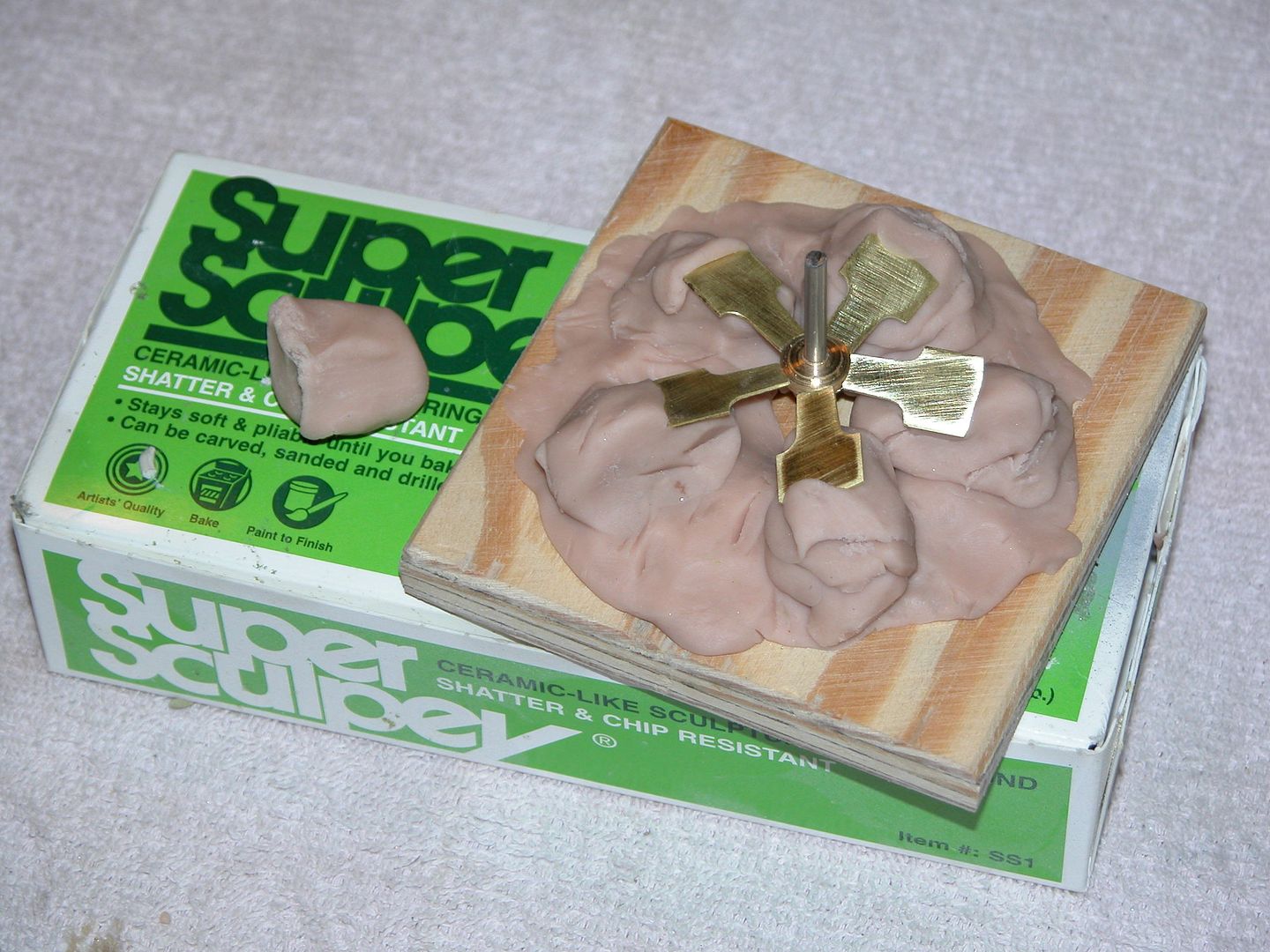
    I was casting blocks (blanks) of polyurethane resin and foam. The blanks then became filler blocks or substrate for carving and/or machining. Now I just go with the commercial product, RenShape. Loren Perry was the guy who taught me how to secure propeller blades to the hub as the entirety was brought up to heat for soldering.


    Super Sculpy is another good choice of material to hold the blades in proper alignment during the soldering process.
    M
    Last edited by He Who Shall Not Be Named; 06-24-2016, 06:38 PM.

    Leave a comment:


  • bwi 971
    replied
    Yeah.....it was in 1997 when I first read your cabal reports making a pumpjet..........still remember thinking how on earth will I ever be capable of making one of those........and after 20 years I'm still pondering on it.
    I remember you made it out of renshape......your casted that stuff into blocks (cubes) yourself in those days no?

    Grtz
    Bart

    Leave a comment:


  • He Who Shall Not Be Named
    replied
    Store your photos and videos online with secure storage from Photobucket. Available on iOS, Android and desktop. Securely backup your memories and sign up today!


    ​Variation on a theme

    Leave a comment:


  • He Who Shall Not Be Named
    replied
    A great job on that propeller blade assembly jig. Loved the use of wet sand as a support grout -- I'll steal that. Yet another reason to hate you European types!

    ​M

    Leave a comment:


  • bwi 971
    replied
    Propeller finishing diameter 40mm (1.6").

    ​ 2 blades of the prop were slightly off regarding the diameter....It was starring at me every time I looked at the propeller.......so I needed to address.
    The problem is You can't heat 2 blades without melting the solder of all the others.
    I took a piece of pipe turned the inner diameter to the required diameter of the propeller 40 mm in my case.
    Made a support for the blade roots, mounted the propeller on the jig with the root support, put the pipe over the propeller, filled the casing with sand halve way the propeller height, wetted the sand with water and heated everything up. When everything was hot enough I adjusted the blades till they touched the pipe casing and let everything cool down again. Put the propeller on the lath, turned the lath on, and I saw a perfect propeller NO MORE STARING.
    Click image for larger version

Name:	Akula (661).JPG
Views:	162
Size:	82.4 KB
ID:	114937
    Click image for larger version

Name:	Akula (665).JPG
Views:	138
Size:	70.9 KB
ID:	114940
    Click image for larger version

Name:	Akula (663).JPG
Views:	116
Size:	72.4 KB
ID:	114943
    Click image for larger version

Name:	Akula (664).JPG
Views:	132
Size:	83.2 KB
ID:	114939


    While I was doing that I thought lets finish this thing........I saw on some pictures that sometimes the propeller of the AKULA's is provided with zinc anodes.....I casted some anodes with use of solder, they are approxiatly 1.5mm in diameter, and glude them on the hub.
    Now the propeller can go into the finished box.
    Click image for larger version

Name:	Akula (667).jpg
Views:	150
Size:	52.2 KB
ID:	114944
    Click image for larger version

Name:	Akula (659).jpg
Views:	96
Size:	40.8 KB
ID:	114942
    Click image for larger version

Name:	Akula (658).jpg
Views:	137
Size:	40.8 KB
ID:	114941


    Click image for larger version

Name:	Akula (656).jpg
Views:	119
Size:	41.7 KB
ID:	114938


    This pic showing the prop of a KILO class I used it as an example for the anodes.
    Click image for larger version

Name:	image001.jpg
Views:	156
Size:	43.8 KB
ID:	114945


    Grtz,
    Bart


    Last edited by bwi 971; 06-24-2016, 03:03 PM.

    Leave a comment:


  • bwi 971
    replied
    I did consider a pivoting arm but I thought I could do it this way. Pivoting arms are restricting access, I have one in front to move the bowplanes.

    I made the dogbone 10mm wide so I have a large contact area with the pushrod so that is covered regarding clearance and flex of the dogbone itself.
    But I have indeed some flex from the pushrod within the gland of the endcap. So I have to make a guide on the endcap to support the pushrod/ dogbone.

    If it doesn't work I make a pivoting arm afterall.

    Grtz,
    Bart

    Leave a comment:


  • HardRock
    replied
    Are you getting much flex at the dogbone end? And did you consider using a pivoting arm instead of the dogbone?

    Leave a comment:


  • bwi 971
    replied
    Pushrod bowplanes,

    I made a dog-bone connection to redirect the pushrod for the bowplanes to the bottom of the SD and fabricated some guidance taps to guide the pushrod all the way up to the fwd part of the SD.

    Grtz,
    Bart

    Click image for larger version

Name:	Akula (651).jpg
Views:	206
Size:	42.1 KB
ID:	114917

    Click image for larger version

Name:	Akula (655).jpg
Views:	182
Size:	41.8 KB
ID:	114920

    Click image for larger version

Name:	Akula (652).jpg
Views:	169
Size:	48.7 KB
ID:	114921

    Click image for larger version

Name:	Akula (654).jpg
Views:	138
Size:	38.5 KB
ID:	114919

    Click image for larger version

Name:	Akula (653).jpg
Views:	161
Size:	37.3 KB
ID:	114918

    Leave a comment:


  • bwi 971
    replied
    I'm just sharing info received from others Scott....nothing more nothing less. That's why I like this forum.

    Grtz,
    Bart

    Leave a comment:

Working...