Akula 1/144 Scratch built

Collapse
X
 
  • Time
  • Show
Clear All
new posts
  • bwi 971
    Captain
    • Jan 2015
    • 901

    #76
    Ok FINALY some progress:

    Readdressed the rudders and planes,
    ​When I made the transition with the hull to much material was removed a slight reses was the result. Two coats of primer (red colour) iwo the curve solved the problem.

    Click image for larger version

Name:	Akula (342).jpg
Views:	99
Size:	60.4 KB
ID:	110780

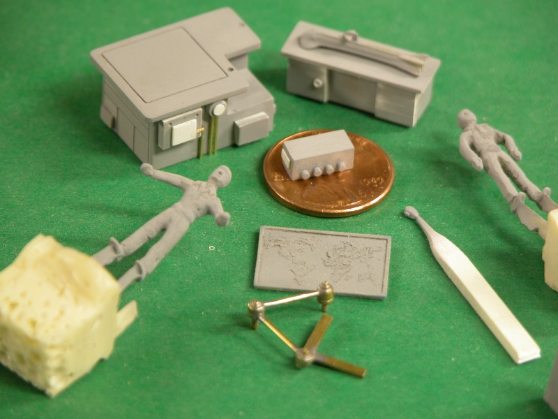
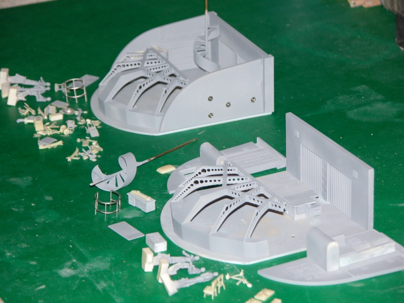
    all parts in the Paint box

    Click image for larger version

Name:	Akula (341).jpg
Views:	84
Size:	73.7 KB
ID:	110781

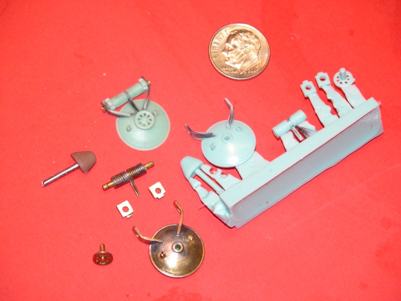
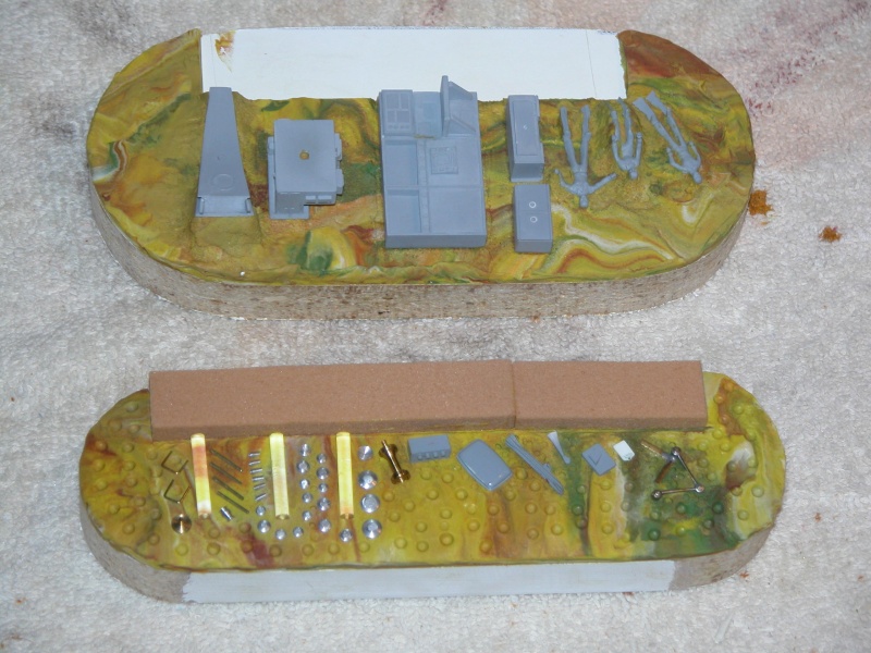
    Horizontal SOKS 6 needed 2 spare; body 2.5mm brass rod support 1mm styrene::

    Click image for larger version

Name:	Akula (337).jpg
Views:	83
Size:	51.7 KB
ID:	110772

    Click image for larger version

Name:	Akula (333).jpg
Views:	81
Size:	69.9 KB
ID:	110774

    Click image for larger version

Name:	Akula (328).jpg
Views:	76
Size:	70.1 KB
ID:	110773

    Vertical SOKS: 3 small SOKS, 2 big protectors; 2x1.5mm styrene sheet:

    Click image for larger version

Name:	Akula (338).jpg
Views:	92
Size:	49.9 KB
ID:	110776

    Click image for larger version

Name:	Akula (335).jpg
Views:	83
Size:	54.9 KB
ID:	110777

    Click image for larger version

Name:	Akula (329).jpg
Views:	85
Size:	58.9 KB
ID:	110775

    Inlet Scoops (round instead of the fin type), 2x4mm styrene sheet inlet still to be opened up:

    Click image for larger version

Name:	Akula (334).jpg
Views:	80
Size:	57.6 KB
ID:	110779

    Click image for larger version

Name:	Akula (331).jpg
Views:	83
Size:	66.5 KB
ID:	110778

    Grtz,
    Bart


    Practical wisdom is only to be learned in the school of experience.
    "Samuel Smiles"

    Comment

    • Peter W
      Captain
      • May 2011
      • 509

      #77
      Bart, Your paint booth is more technical than mine ! Based on the reactor scoops that you have painted are you building one of the first 4 Akulas or do you just prefer them to the flatter one?

      Peter

      Comment

      • bwi 971
        Captain
        • Jan 2015
        • 901

        #78
        Hi Peter,
        Your right and here ’is the story behind it:

        The fin type scoop was constructed at the beginning of the project, just wanted to build a akula.
        During the build I got more and more information concerning the diferent flights, Vepr157 on another forum helped me out.

        I had an Akula pictue with the vertical SOKS fin flanked by two slightly larger fins. Vepr157 explained that this was an early SOKS system and only one sub was equipped with this, the K-480 “AK BARS”

        As I never saw a model of this sub I decided to go and make the K-480 “AK BARS” an AKULA I---FLIGHT I the 4th Akula constructed.

        She was the last one provided with the round scoops so I had the redo the scoops.

        Grtz,
        Bart
        Click image for larger version

Name:	K-480 AK-1-FL-1-010 bis.jpg
Views:	90
Size:	96.6 KB
ID:	110793
        Practical wisdom is only to be learned in the school of experience.
        "Samuel Smiles"

        Comment

        • Peter W
          Captain
          • May 2011
          • 509

          #79
          Bart, I know the forum you mean, that chap has a lot of good info to share. I like the idea of the individual touch on your chosen hull. Obviouslywith my Scaleships Akula I have the later type reactor scoops that come with the kit. Having said that I am not a rivet counter but I do like a lot of detail on my boats therefore if I come across something that isn't actually on the full sized Vepr but another boat I will probably add it for interest. Keep at it, it is coming together well.

          Peter

          Comment

          • bwi 971
            Captain
            • Jan 2015
            • 901

            #80
            Originally posted by He Who Shall Not Be Named

            Smart-ass Europeans! (I'm thinking of assembling your SD with water-soluble glue).

            M
            Just placed the order......delivery will take 4 days......add 4 fabrication days (water-soluble glue cures fast).......happy to see her arrive the week after next.
            grtz,
            S-ass


            Practical wisdom is only to be learned in the school of experience.
            "Samuel Smiles"

            Comment

            • bwi 971
              Captain
              • Jan 2015
              • 901

              #81
              Originally posted by Peter W
              Bart, I know the forum you mean, that chap has a lot of good info to share. I like the idea of the individual touch on your chosen hull. Obviouslywith my Scaleships Akula I have the later type reactor scoops that come with the kit. Having said that I am not a rivet counter but I do like a lot of detail on my boats therefore if I come across something that isn't actually on the full sized Vepr but another boat I will probably add it for interest. Keep at it, it is coming together well.

              Peter
              Just came across this picture Peter.

              The sail SOKS on the k-154 Tigr (left in the picture) differed from the others (bull horns).....now they change the ones on the K-317 Pantera (right) accordingly.
              I'm lucky the K-480 was decommissioned so I don't have to continuously change her outfitting’s.


              Grtz,
              Bart


              Practical wisdom is only to be learned in the school of experience.
              "Samuel Smiles"

              Comment

              • Peter W
                Captain
                • May 2011
                • 509

                #82
                Bart, never 2 the same !The position of the vent flap thingys show that.......... Is it just me or does the rudder pod on Panther look bigger ?

                Peter

                Comment

                • bwi 971
                  Captain
                  • Jan 2015
                  • 901

                  #83
                  I have been working on the aft escape hatch.

                  The round body is made out of 2mm (0.078”) acrylic sheet.
                  The hatch cover is made out 1mm (0.04”) acrylic sheet.
                  The valve handle is made out of 0.2mm (0.0079”) diameter wire and glued together with CA.
                  The hinge is made out of 1.5mm ( 0.059”) diameter brass rod made scuare 0.8x0.8mm (0.031x0.031”).

                  As I don’t have a 0.0039 diameter endmill I was not able to make the small flood sleeves in the hatch nor the slot in the hinge, very frustrating.

                  Escape hatch of a Typhoon
                  Click image for larger version

Name:	Akula (343).jpg
Views:	90
Size:	72.7 KB
ID:	111268

                  Body and hatch cover
                  Click image for larger version

Name:	Akula (346).jpg
Views:	80
Size:	43.1 KB
ID:	111269

                  Valve handle
                  Click image for larger version

Name:	Akula (344).jpg
Views:	81
Size:	41.6 KB
ID:	111274

                  Click image for larger version

Name:	Akula (345).jpg
Views:	79
Size:	74.3 KB
ID:	111270

                  All parts ready
                  Click image for larger version

Name:	Akula (347).jpg
Views:	81
Size:	36.3 KB
ID:	111275

                  The end result
                  Click image for larger version

Name:	Akula (348).jpg
Views:	82
Size:	33.0 KB
ID:	111273

                  Click image for larger version

Name:	Akula (350).jpg
Views:	89
Size:	39.8 KB
ID:	111272

                  Click image for larger version

Name:	Akula (351).jpg
Views:	81
Size:	46.5 KB
ID:	111271
                  Last edited by bwi 971; 11-15-2015, 03:08 AM.
                  Practical wisdom is only to be learned in the school of experience.
                  "Samuel Smiles"

                  Comment

                  • HardRock
                    Vice Admiral
                    • Mar 2013
                    • 1609

                    #84
                    Bugger. Can't see the photographs. Is it me or you?

                    Comment

                    • bwi 971
                      Captain
                      • Jan 2015
                      • 901

                      #85
                      Originally posted by HardRock
                      Bugger. Can't see the photographs. Is it me or you?
                      I see them but I edited the post and uploaded them again.....hope they are visible now.
                      Grtz,
                      Bart
                      Last edited by bwi 971; 11-15-2015, 04:12 AM.
                      Practical wisdom is only to be learned in the school of experience.
                      "Samuel Smiles"

                      Comment

                      • HardRock
                        Vice Admiral
                        • Mar 2013
                        • 1609

                        #86
                        I see them now and this confirms my earlier assessment.... Bart, you are a MANIAC! God bless you.

                        Comment

                        • He Who Shall Not Be Named
                          Moderator
                          • Aug 2008
                          • 12287

                          #87
                          Originally posted by bwi 971
                          I have been working on the aft escape hatch.

                          The round body is made out of 2mm (0.078”) acrylic sheet.
                          The hatch cover is made out 1mm (0.04”) acrylic sheet.
                          The valve handle is made out of 0.2mm (0.0079”) diameter wire and glued together with CA.
                          The hinge is made out of 1.5mm ( 0.059”) diameter brass rod made scuare 0.8x0.8mm (0.031x0.031”).

                          As I don’t have a 0.0039 diameter endmill I was not able to make the small flood sleeves in the hatch nor the slot in the hinge, very frustrating.

                          Escape hatch of a Typhoon
                          [ATTACH=CONFIG]n111268[/ATTACH]

                          Body and hatch cover
                          [ATTACH=CONFIG]n111269[/ATTACH]

                          Valve handle
                          [ATTACH=CONFIG]n111274[/ATTACH]

                          [ATTACH=CONFIG]n111270[/ATTACH]

                          All parts ready
                          [ATTACH=CONFIG]n111275[/ATTACH]

                          The end result
                          [ATTACH=CONFIG]n111273[/ATTACH]

                          [ATTACH=CONFIG]n111272[/ATTACH]

                          [ATTACH=CONFIG]n111271[/ATTACH]

                          To make those slots: Find or shave a piece of .0039" brass or copper sheet, Cut a strip of it to the length of the hatch fairing cover flood sleeve. Heat it with a candle and press its end into the plastic fairing piece (I assume the plastic is of the thermoplastic type). It will sink in. When cool, pull the metal strip out and with a knife lop off the ridges formed around the strip -- revealing a perfect flood sleeve (slot) of uniform depth and shape.

                          Damn, I'm good!

                          M
                          Who is John Galt?

                          Comment

                          • bwi 971
                            Captain
                            • Jan 2015
                            • 901

                            #88
                            Originally posted by HardRock
                            I see them now and this confirms my earlier assessment.... Bart, you are a MANIAC! God bless you.

                            About the maniac thing.....my missis says your right 100%

                            Originally posted by He Who Shall Not Be Named


                            To make those slots: Find or shave a piece of .0039" brass or copper sheet, Cut a strip of it to the length of the hatch fairing cover flood sleeve. Heat it with a candle and press its end into the plastic fairing piece (I assume the plastic is of the thermoplastic type). It will sink in. When cool, pull the metal strip out and with a knife lop off the ridges formed around the strip -- revealing a perfect flood sleeve (slot) of uniform depth and shape.

                            Damn, I'm good!

                            M
                            Ok challenge accepted sir.....will revert to you soon.....by the way I hate you.

                            I know everybody is breathing I your neck David but when you have a moment to spare can you please explain the vacuum casting technique.

                            My vacuum storage tank is ready to go as you told me pa….and I think I’m gonna need it to cast the small parts?

                            Grtz,
                            Bart
                            Practical wisdom is only to be learned in the school of experience.
                            "Samuel Smiles"

                            Comment

                            • He Who Shall Not Be Named
                              Moderator
                              • Aug 2008
                              • 12287

                              #89
                              Originally posted by bwi 971


                              About the maniac thing.....my missis says your right 100%


                              Ok challenge accepted sir.....will revert to you soon.....by the way I hate you.

                              I know everybody is breathing I your neck David but when you have a moment to spare can you please explain the vacuum casting technique.

                              My vacuum storage tank is ready to go as you told me pa….and I think I’m gonna need it to cast the small parts?

                              Grtz,
                              Bart

                              NO! ... I hate you first!

                              M

                              (I'm working up a piece on vacuum assisted resin casting as I hate you. Give me a few hours, pal)
                              Who is John Galt?

                              Comment

                              • He Who Shall Not Be Named
                                Moderator
                                • Aug 2008
                                • 12287

                                #90
                                Originally posted by bwi 971


                                About the maniac thing.....my missis says your right 100%


                                Ok challenge accepted sir.....will revert to you soon.....by the way I hate you.

                                I know everybody is breathing I your neck David but when you have a moment to spare can you please explain the vacuum casting technique.

                                My vacuum storage tank is ready to go as you told me pa….and I think I’m gonna need it to cast the small parts?

                                Grtz,
                                Bart


                                Bart wants the dope on an aspect of casting. Specifically, vacuum assisted casting. Vacuum castin simply removes air from the tools cavities, either by voiding air through the pourouse ceramic tool (high-temperature work, usually silver or gold), or frothing the resin momentarily as the applied vacuum extracts cavity air through the resin filled sprue trough. Explained later.

                                Resin or metal casting, the name of the game is getting a liquide (of usually thicker-than-water consistancy) to completely fill the voids (cavities) of a mold (tool), doing so before the liquid changes state, through freezing or heat induced polymerization of the liquids molecules. The beauty of vacuum casting is that no vent, risers, or gates -- other than the sprue communicating the liquid metal or resin to the tool cavities -- are involved. This results in a cast part free of vent, gate and riser nubs that have to be ground back and finished.

                                But, the big advantage is that the most complex of cavity geometries will be filled completey without bubbles being entrapped during the state change, ruining the finish of the part.


                                The typical vacuum assisted resin tool is made much the same way and uses the same rubber as used for normal resin gravity or pressure casting. The difference is that the vacuum assisted tools sprue is a simple long, deep, narrow, open faced trough communicating with the cavities under it through short, narrow auxiliary sprues. No vent channels.

                                The above very complicated and small masters were used to make of the several vacuum assisted resin casting tools used to produce parts for the 1/96 structures and figures of the Teskey SEAVIEW observation compartment.

                                (Note the little SEAVIEW 'model' master -- it's one-inch long, sports-fans. Yeah ... I hate you too, Bart!)


                                This is what your typical vacuum assisted rubber tool looks like. Note that the only sprues are at the feet and hands of the figure parts, leading to the big trough sprue piece. Had I gone with gravity these things would never, in practice, have been complete shots. And even if I went with pressure casting I would have been obligated to provide an extensive vent and header system to vent the displacing air, even then I would have had some short shots -- a waste of time and money.

                                Note that the hardened resin from the trough produces a big-ass foundation upon which all the cast parts stand. Nice thing about that is it gives you a handle that makes flash trimming, de-greasing, priming and painting a less frustrating task -- easy to hold parts. Like the figure masters above: each a blanks that became SEAVIEW crew masters with some alteration with knife and putty.


                                You need at least 28.5 inches of Mercury pulled by your vacuum pump ... that's outer space thin, boys and girls. The best set up is a volume tank that is evacuated before you mix your resin. You mix up the resin; pour it in the tool, half-way filling the trough; place the tool on the vacuum table, slip the bell-jar over the tool; and slam the vacuum to it. In the absence of air over the trough, the air under it -- within the tool cavities -- rushes up and through the resin filled trough, breaking the liquid resins surface as frothing bubbles which pop and the air drawn out and into the pump or volume tank. As the air leaves the tool cavities, its displaced by the resin. You vent air back into the machine and wait for the resin to cure hard enough to de-mold, and you're done. Slicker than snot!

                                See all that nasty resin coating the inside of the bell-jar? Guess how that happened? Some idiot did not make the trough deep enough on one of his earlier vacuum assisted tools. Every watch Outland? No flying eye-balls, but plenty of resin went its own way on that one! I learn the hard way. You don't have to!


                                If you want to reinforce the resin parts with fiber or the like, vacuum assisted casting permits a complete saturation of the weave, such as these carbon reinforced hatch horns. Note that this one sprue contains all the parts (less escape buoy bail) needed to produce a very nicely detailed submarine deck hatch. The masters used to produce the tool cavities were fabricated from brass, Renshape, and soft wire thread.


                                1/96 observation compartment small resin parts were almost exclusively fabricated employing the vacuum assisted resin casting process. Small items of complicated form are best done this way as any other method (other than centrifugal casting) will likely produce parts pock-marked with bubble-voids.


                                To the left are resin parts fabricated using a typical gravity pour, pressure assisted process -- the need and use of vent channels demonstrated here. To the right are four sprues with many small and deeply detailed parts -- no vent channeling or other artifacts of the other casting process here, just the big trough, and auxiliary sprues, and that's that.


                                Two vacuum assisted tools under construction. The masters are half masked in modeling clay. Yeah, I even made masters of a typical holiday dinner service, right down to the gravy-boat (must have been out of my frig'n mind!). Note the Renshape block used to give form to the eventual sprue trough.
                                Who is John Galt?

                                Comment

                                Working...