-
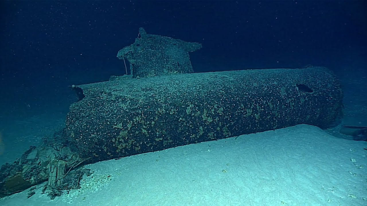
Interesting recent video about one of the wrecks that was found by the navy years ago but not made public.
-
Finally finished the work on rebuilding her to the type B Version, due to the bad weather it took some time to slap on some paint, it had to happen between the rainshowers all these days.
Builded her together to adress some issue's, during priming i discovered some seems on the hull, had to clean them up first with some putty.
All parts painted with three layers, as a mentioned before, it took some time because of the weather, i like to spray my stuff outside.
Builded up the boat to see what the result would be, for now she's ready to be trimmed, i suspect the front will be heavier and the rear will be lighter, added some extra foam between the launchingtubes to counteract the weight of the frontpart, probably have to add some weight in the rearpart.
First i have to see if she will fitt in the bath due to the length, otherwise i have to wait for next spring when the testpool is build up outside.
Manfred.
Leave a comment:
-
Done a lot this week, finished up the rearpart and sprayed some etchprimer today,
The first cut on the stabilisors, decided to leave some more meat, otherwise i will end with flimsy stabilisors.
Second cut, followed the outlining of the new rudders, it's starting to become something.
Drilled the new location of the shafts and placed the new rudders, used some clamps to keep them at position.
After making the new steeringcontrols and placing the reiinforcement bars i discovered the throw of the rudder was limited by the bars.
By making a 45 degrees bevel on top of the rudders i've got me some more room to move them.
The finished rearpart, it does like the real one, not exactly the same but close enough.
Found out that the front navigationlight was different, made this item and had to grind away some of the lower structure, by doing this, the light is visible from the front of the netcutter.
Took everything off from the model which i don't want to paint, time to use some primer.
Today i've got me a break in the weather, which means time to use some primer, all items are done, due to the weather it can dry, after that i can store the items 24 hrs for hardening.
Manfred.
Leave a comment:
-
Finished up the frontpart, made preparations for attacking the rearpart with the Dremel
First batch of protecting plates, that book i bought some time ago gives me usefull information with pictures where to place them
From that book i found out there are long tubes (possible with wires inside) with a oval end, from what i understand, they are use to control the little claws around the protecting covers of the torpedo's, that plunger thing at the front is used for seperating both covers, which are linked by a chain, so when you want to use the torps, first free the claws and use the plunger to push off the covers, since they are linked by a chain, both covers will fall off, ready for using the torps.
Both sides completed, still need some sanding to clean up the soldering joints, then it will be ready to be treated with some etch primer.
This is where i stand with the rearpart, by using the book i've signed off the cuts i want to make, have to cut the upper and lower stabilisors and new openings for the rudders, from that point i can change the steering of the rudders, since the shaft steering the rudders shifts forward i've got to rebuild the steering mechanism inside the rearpart.
Manfred.Leave a comment:
-
First total pictures of the change from the type A to the type B, still a long way to complete this.
Accourding to the pictures i have made the seperations with some copper plate, from that point i could start with those tiny claws which keep the protecting covers into it's place, placed one to see if i'm on the right track.
In total i had to make 8 claws, took some styrene and copper 1 mm rods bent into shape.
Placed all claws all around, next step will be adding the coverplates which will protect the claws, that will be a job for next time, adding those details takes time, but on the end she will stand out in the crowd
Manfred.
Attached FilesLeave a comment:
-
-
Well it was refreshing talking about print technoligy, let's show what can be build by using some copper plate and the soldering iron,
Like the type A, the type B has a perosope protector, it's also used in conjuction with the front netcutter, those edges on the protector will support the cutting of the net.
Also placed the bars on the front net cutter, still have to bend it more into shape.
This one has a story, i made this as a test to see if i could use the remaining old stringers, on this moment SWMBO walked into the cave and started to laugh, giving me the comment, you can do better, she gave me the idea to make this work.
The idea she came up with was, use the curved parts of the front net cutter, and it worked, never tell the wife she has good idea's, so this was all made by using my brillaint brains.
In the end the nose part was build from 5 pieces, giving me a sound base to add details in the future.
I still had to come up with a other way to fasten the front part.
This way i can take the front part off, in the future it will be permanent fastened.
Made a make shift key to fasten the front part.
It was used to tighten the new screw part which will hold the front part.
Seen from the front, it will stay there permanently, now i can start researching which parts there will be placed at the front part, and what other changes i have to make to the hull if needed.
Manfred.
Attached FilesLeave a comment:
-
-
Thanks Tom,
I have to change the rudders anyway, she steers like a pig with the old rudders, so rebuilding the boat to a B type, which has the new rudder configuration, is for me a no brainer, let's see if this will work out,
this weekend some udates on the progress, stay tuned
ManfredLeave a comment:
-
Busy days, managed to get the tower netcutter build and made the netcutter on front of the boat, still have to add the details on some parts but the beginning is there,
Soldered all pieces together, giving you this, the basic layout of the tower netcutter.
Those curved parts need to be reenforced with some little bars between the curved parts, i will do that at a later stage.
The beginning of the front netcutter on the bow, it's pretty basic, only had to add the contruction which hold the upperpart.
Dryfitting the netcutter on the tower, all other parts of the tower have to be modified.
In the past i've builded the tower in such way that i can take all parts off by simply unscrewing two bolts.
Added the rivets which holds the netcutter to the tower, those rivets are glued tight from the inside of the tower, the rivets on the hull are only glued at one side, giving me the possibility to lift the tower without any problems.
The new configuration to the type B conversion, there's loads of work more, but i've got me a beginning.
The new netcutter on the bow, secured with 1 mm rivets and glued down, that new stringer pointing out will be a part of the new bowpart which protects the torpedo tubes.
For now i've got to add some details and start thinking how to build the new protector of the torpedo tubes, from what i've seen on the pictures this will be interesting to build.
Manfred.
Leave a comment:
-
More progress on the rearpart, and a grazy idea to convert the boat, pictures
Everthing is soldered, still have to add some details, but the base is there.
Made the new rudders from 5 mm plexiglas, those are 4 times bigger as the old ones, hope that will to the trick.
And now my grazy idea, since i alter the rearpart as on the type B, why don't rebuild the boat as a type B?, made some drawings to see how it will look.
Trying the drawing on the tower, i think it's badass, some strange netcutter on the tower.
Since the decision was made, placed some clear Vivak on top of the drawings, this way i preserve the drawings for a next time.
First step in getting the netcutter, bended some copper into the right shape and made a dry-fitt on the drawing.
Those parts have a U shape, by using the vice, hammer and some wood i managed to get the shape right.
The top netcutter ready to be soldered.
Yet again a dry-fitt before i solder those parts together, tomorrow i will turn my attention to that curved part of the netcutter, to be continued.
Manfred.
Leave a comment:
-
The innershaft is running in copper bushings, used a carbon shaft for the innerpart to get lesser friction.
Manfred.Leave a comment:
-
Is the inner shaft running in bearings/bushings or up against the full length of the outer shaft/tube?Leave a comment:
-
This boat is still resisting me to work properly, last meeting in Germany i had to swim AGAIN!!!! to get her on the shore, after that i putted her aside on the shelve, lately came up with some new idea's and placed her on the bench.
As for steering, pretty much the same story, enlarged the lower rudder to no result, best option is to go for the rudders used in the type B variant.
First i decided to get me a new drive-line, those are the parts i've made.
A better view how things work, those gears driven by the inner shaft are used to get the top O-ring spinning, which will turn the outer shaft.
Closed up the contraption for testing, if i remember right it was Romel who gave this idea about this configuration for spinning both props.
Did some rigirous testing with the upper drive-line, it works, but too much friction when using the standard E motor of the SD.
The new lower drive-line is made with some pinion-gears and a Carbon shaft, pretty much the same i did with the old drive-line in the past, this time made it more sloppy to avoid waterhammering, testing revealed a smooth run in both directions.
Since the drive-line is running smooth i turned my attention to the steering problem, first step will be altering the cage to a model B type, so i can use the enlarged rudders present on this model, for now it's dry fitted with some clamps, ready to be soldered, to be continued
Manfred.
Leave a comment:
-
I has been some time, but due to the good weather i decided to slap some paint on the boat.
First step, remove all things which i don't want to spray in the colour of the boat
Splitted the boat in four part, hanging from wires in the garden.
First run of paint, in the end i gave her three layers, better thin in the beginning, adding paint is allways possible.
When the paint dried and hardened i build her together from all loose components.
Made the propellors looking brass, stil have to weather them down.
Conningtowerl is build up, inside of the hatch has become white.
And finally the business endt to the submarine, gave the torpedo-dummy's the same colour as the hull, those can be removed to be replaced by some live torpedo's
Manfred.Leave a comment:
-
Despite the fact i didn't trim the Type 17 because of bad weather i made a attemp at enlarging the lower rudder of the Ko Hyoteki, pictures
Step one in the process, have to get the cone part seperated from the rest.
This piece is held at his place with two small pins, once removed you can separate the parts as on the picture.
Made some lines for the piece i wanted to cut.
First pass with the cuttingwheel of the dremel.
Used a baby-saw to get the piece cutted free, wanted to re-use the cutted piece for enlarging the rudder,
Made on both pieces cuts with the cuttingdisk, this was done to get me a small strip of copper between the parts to give some more strength.
Initially i used superglue and bakingsoda the get me the position right of both parts.
For now i'm at this stage, glued the parts with epoxy glue, this has to set first, i'll leave both parts in the rough, first want to test if this helps, if not i will repeat the same at the top rudder.
Manfred.
Leave a comment:

Leave a comment: