
25% is adequate
-
-
Ok I wanted to add a quick update. I have been printing all of the detail (resin printing ugh) parts so been busy with that, and trying not to die of toxic poisoning in the process. What a pain resin printing is, I can't believe people like it but I digress. I wanted to show my preliminary design for functioning forward dive planes. Attached is a picture of the cad design. The idea is to place a waterproof servo with a gear between the dive planes in the upper part of the hull there, and have another gear driven by that, so the gears rotate opposite each other. This will deploy and stow the planes. To drive them, a linkage from the wtc to the planes, in the lower hull. The drive axles will have linkage attached to them, and then a hole will be made for them to pass through and attach to the wtc linkage. I have them drawn upwards right now, with no holes for them, but that is coming, they will ultimately point down through slotted holes. Ps I modified the original design so the dive planes will have stainless steel pins at the drive axle attachment, as well as the top where the stow axles are. I am using tied rod ends from a rc vehicle (Amazon purchase) and the stow axles will be 1.6mm threaded rod.Last edited by billyd; 04-03-2024, 11:58 AM.Comment
-
Mostly finished the functional diveplanes. Have a few more details to iron out but I've got enough to print and test it. Waiting on parts.
Ps a big thanks to the original designer (of the SSN-571 3d printed model) for giving me the hull section #2 step file. I will share the design with him when complete and he will incorporate it into his model.
Last edited by billyd; 04-30-2024, 05:08 PM.Comment
-
Here is the stowed position. I also made some more changes.
Comment
-
Building second prototype now. Design should be finalized. First one worked ok but hard to assemble. Made many improvements to strength as well.
Comment
-
Complexity Warship on display... Rube Goldberg would be so proud.
Pull yourself away from that damned computer and march your butt back into the shop and get some real work done.
KISS!


David
Who actually Builds stuff!Last edited by He Who Shall Not Be Named; 05-08-2024, 05:30 AM.Who is John Galt?Comment
-
The bow planes on the 571 are not co-planar, in multiple axes. I wish I had it so easy. Prototype will be done soon.Comment
-
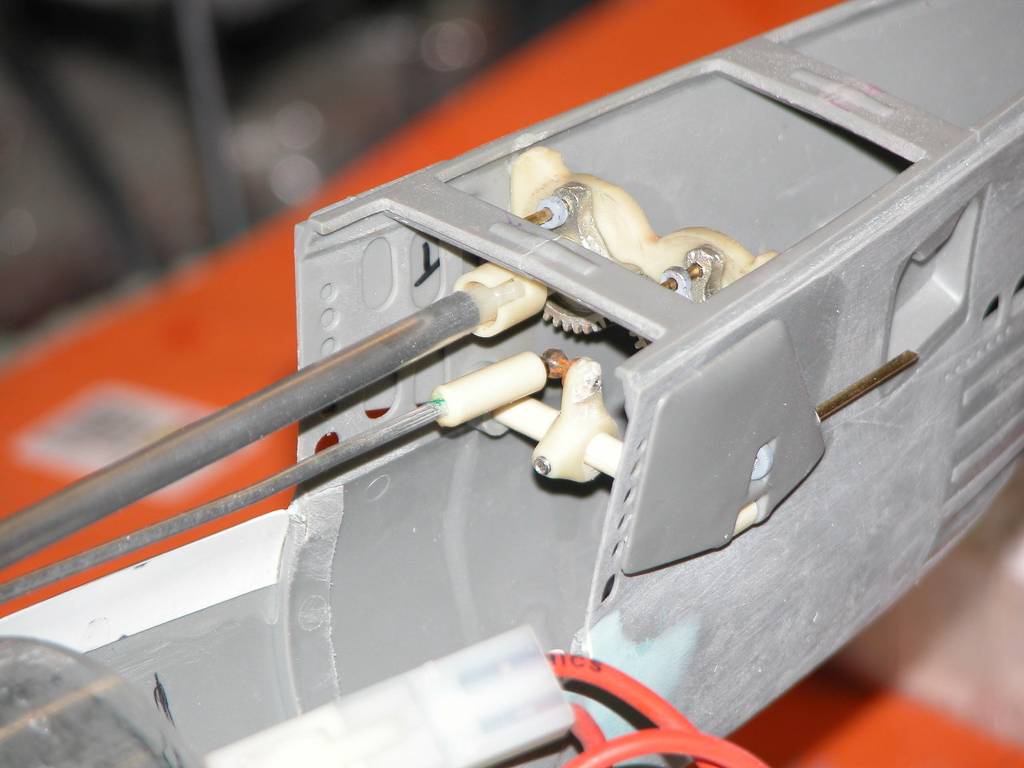
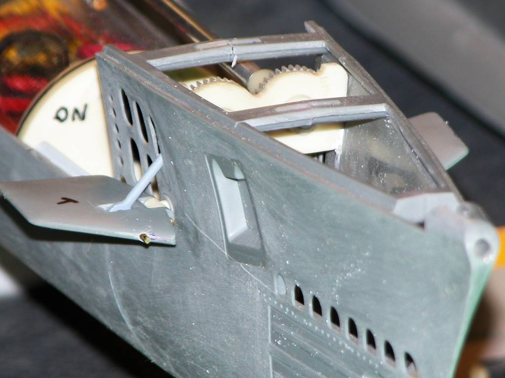
There is nothing rube goldberg about the design. We can agree to disagree. It is a much more difficult design than the photos you show because the space available in the 3D print is very limited. I wanted to leave the torpedo area below unimpeded in case in the future I wanted to add functional torpedos. This is a 1/72 scale, so I had about a total of 65 x 45 x 35mm to work with and fit everything in. I also couldn't use typical helicopter links at the gears, because I need to be able to thread the stow/deploy bars into the dive plane links otherwise assembly would be very difficult and you can't fit your fingers (or small plyers) in to do it. It has to be done with a very small screwdriver. Also the dive plane angle drives have to be removable, to ease the assembly process. Or especially if you ever needed to replace the dive planes. They are separate because they rotate about two different planes, and it's actually simpler than trying to do it with one piece. Finally the entire assembly can be removed from the rest of the sub to work on. And can be reinstalled fully assembled on to the sub. I have a working prototype and it works flawlessly. Pictures to follow.Comment
-
A few pics.
Comment
-
Here is a repeating servo test of the retractable bow planes
Comment
-
I am going to attempt to make the torpedo doors functional. I think this might be very difficult but I'll give it a shot. Question for the board, on the real sub can anyone tell me if the doors were opened either individually, in pairs or all together, or in some other sequence? Much appreciated. Obviously all at once would be the simplest approach and I may even be forced to do it that way. But I'd like to start out at least attempting to keep it as realistic as possible. If I have to, I can cower down to what I can actually achieve lol.Comment
-
Shutter doors are normally opened individually.
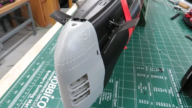
One of the biggest (aesthetic) improvements for this otherwise, excellent 3D model is the inaccurate sail shape. If you can get the orignial sail STEP file and remove the angled leading edge of the sail, the change is is very noticable.
Comment


Comment