-
make your pictures bigger. As sized now they convey little useful information. -
Wheelhouse Deck Carpeting
The wheelhouse deck of the Disney Nautilus was carpeted in a pattern of blue squares on a background of dark blue. My goal was to make a reproduction as accurate as I could, I had to figure out a way to create this carpeting. I knew that I could not paint it on by hand, so I came up with a way to print it.
After some searching I discovered that a waterproof paper does exist. Apparently it was developed for use in menus. I found the following at Staples…
PuffinPaper Synthetic Waterproof Paper
I did some test prints and it did hold the color and did not bleed when immersed in water.
I also did some tests with different adhesives to find out what would secure it to the deck best. CA glue was not good. Epoxy worked perfectly except that it was impossible to remove the waterproof paper. In the end Rubber Cement worked best. It held well to the deck but was relatively easy to remove the waterproof paper in order to replace it.
The only remaining problem was how to accurately recreate the pattern and colors in the carpet on the same scale as the wheelhouse.
After trying several different approaches it turned out that using Excel worked the best for creating the pattern of squares and the colors. I have to say that I should have gone a darker blue for the background color.
In Excel, once you've created the pattern of squares using a size that is convenient to work with you can shrink the pattern down using the Display % feature. It prints out true to the shrunk size. Then it's a matter of cutting it out and glueing it to the deck.
Last edited by Johnny Depth; 01-04-2024, 08:00 PM.Leave a comment:
-
Hidden Wheelhouse Lighting
Alligator Eyes
By drilling through the Alligator Eyes along the housing, the drill bit will emerge out of sight beneath the left and right Wheelhouse Inserts. In order to do so, I created a drill guide.
The LEDs for the Alligator Eyes had to be 5mm in diameter to fill the "eye socket" and it had to be short enough to fit in the space before the hull angled down. After looking at many different LEDs, I finally found this one, which met all the requirements.
SuperBrightLEDs.com #RL5-W4575, cool white, 5mm diameter and the body is just under 6 mm. It has a large green circular pad where the light is emitted and I think it gives it a somewhat menacing look. You can see it in the first picture I sent above.
Using a Dremel drill with a small spherical bit, I excavated space for the LED to sit and used CA glue to fix them down.
The two Alligator Eye LEDs were wired in series to save a bit of space. Only one resistor needed.
WHEELHOUSE INTERIOR LIGHTING
My goal was to hide both the LEDs and their wires from view. I also wanted the wheelhouse to be as brightly lit as possible to try to reproduce the famous glowing yellowish viewports in the Disney movie. To accomplish this I used I chose the Evan Designs Warm White DEKA size chip LEDs.
I found that if I placed one above the ship's wheel in the corner where all the walls met, it would be barely out of sight when the wheelhouse was attached to the hull. In order to hide the wires coming from the DEKA chip, I used a drill bit to rout a trench for the wires running from the chip, underneath the Ballast Lever Block and on under the left and right Interior Wall inserts. Then I tacked down the wires in the trench in a few places and finally I filled and sanded the trench for painting.
How to light the remainder of the Wheelhouse interior while hiding the lights and their wires from view through both the Viewports and the Rear Wheelhouse window was the next problem to solve. I tried gluing the chip LEDs to the overhead surface of the left and right Wheelhouse Wall inserts and running the wires through small holes beside the chips but that didn't work. The chips and their wires were still visible.
The solution turned out to be attaching the DEKA Chip LEDs to the hull and cutting out squares in the Wheelhouse Wall Inserts directly under the lights. A single row of 4 lights, centered in each section of the Wheelhouse. Each "section" having different lengths.
So to implement this solution, I took a piece of mm graph paper and marked the size of each section (the digits you see) and the position of the section supports/dividers (the black squares). Then I cut out a thin rectangle of clear plastic and taped it on top of the graph paper. I used a straight-edge to line up the LEDs nice and straight and glued them in place onto the strip of plastic one by one using CA glue. Then this plastic sheet of LEDs was lined up with the section supports using only one of the inserts so you can see what you're doing. The line of DEKA lights were positioned along the center line of the hull.
The next step was to cut out a rectangular hole for each LED chip; half of the rectangle from the Left Insert and half from the Right Insert. I used an Exacto Knife with a pointed angled blade for this. The edges of the inserts are pretty thin along the edge and it is pretty easy to cut. This whole approach takes advantage of the fact that the Left and Right Wheelhouse Interior Inserts do not sit flush with the hull overhead. There is a gap big enough for these LED chip lights to be recessed and for wires to be run.
Then there's the matter of the wires leading from each LED chip. I deliberately directed all the wires, as you see in the photo above, so that I only had to worry about wires on one side of the wheelhouse. Because the Interior Wheelhouse inserts end up being flush with the hull deck at the bottom, I gouged some shallow tracks for the wires in the hull on that one side. You have to be careful because the hull is only about 1/8 inch thick at that point. Then I drilled corresponding holes in the deck to allow the wires to pass through into the interior.
Result: tons of light and you can't see where it's coming from.
Leave a comment:
-
Last edited by redboat219; 01-03-2024, 07:40 AM.Leave a comment:
-
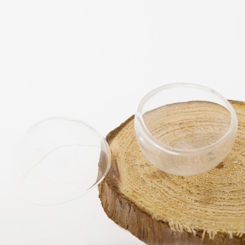
Wheelhouse Main Viewports
According to the Nautilus blueprints the main Wheelhouse View Ports are hemispheres with a diameter of 5 feet. The empty Wheelhouse View Ports in the model measure 20 mm in diameter. So I needed to find something to use for View Ports, preferably glass, with a hemispherical shape and a diameter of 20 mm. I tried a lot of different things over several months and finally found what I was looking for. It turned out to be an automobile lamp; specifically a Sylvania 7440 (or the 7443) Sylvania automobile lamp, available in auto-parts stores. Its cylindrical body is a snug fit for the empty Wheelhouse View Port and it is constructed of fairly thick glass with a hemispherical top.
The only problem left was to cut off the top. To do this, I constructed a jig. The lamp would be placed upside-down in a hole with a diameter slightly larger than the lamp. The hole would not be too deep so that the tail-end of the bulb would stick out above the hole. Then I mounted a Dremel drill with a diamond cutoff drill bit to another piece of wood such that I could rotate the cutoff bit into the side of the lamp to cut at the desired location. By grasping the tail-end of the bulb I slowly rotated the lamp as I cut into it a little at a time until the lamp was cut all the way through.
My success rate was about one good cut out of every 8 lamps. The secret of success was wrapping the bulb with some scotch tape where the cut would take place which cut down on vibrations.
SANDING DOWN THE CUT BULB
I used 220 grit Waterproof Silicon Carbide sandpaper to clean off the edges of the cut bulb.
SIZING THE CUT BULB
The diameter of the Viewport is 10 mm. Therefore the finished height/depth of the cut bulb piece should be 5 mm.
In order to accurately measure the height of the cut bulb I created a bridge using Plastruct Styrene Strips which come in thicknesses of 1.5 mm and 2.0 mm. By stacking these, I created a bridge exactly 5 mm high. If the cut bulb just barely slipped under the bridge, then I knew it was 5 mm high. So I continued sanding the cut bulb until it reached 5 mm.
MOUNTING THE CUT BULB IN THE EMPTY WHEELHOUSE VIEWPORT
I made a mistake here that I have not bothered to correct but it haunts me.
The best way to orient the cut bulb piece into the empty wheelhouse viewport properly so that it could be glued in place was to use a small strip of the Plastic Styrene Strip. I simply held it in place across the opening from inside the wheelhouse and pushed the cut bulb in from the outside. This worked great except for one thing which I didn't realize until I had glued the cut bulb into place. The rivets around the rim of the wheelhouse viewport on the inside lifted the Plastic Styrene Strip by the height of the rivets, so the viewports are recessed a little more than they should be and not flush.
GLUEING THE GLASS VIEWPORT INTO PLACE
I knew not to use CA glue because of the white vapor that it gives off when curing. I hadn't had much luck with Watch Dial Cement. Silicone rubber cement was far too gooey and sticky to use. So I chose Epoxy Cement. And the Epoxy Cement can be removed easily before it hardens using 91% Isopropyl Alcohol.
Leave a comment:
-
complexity warship on display here, Johnny Depth.
KISS!
You tend to make the simple hard.
Do this:


Leave a comment:
-
-
Making the Nautilus RAM
The Ram that comes with the Nautilus is made out of plastic. I thought it should be made of stronger material plus I wanted to try threading the end of the shaft so that it could be screwed into a nut cemented into the hull. So I decided to use the low melting temperature Type 280 Casting Metal. I created an RTV silicone mold of the original plastic Ram and extended the shaft length. It took a while but I finally turned out some good castings. Then during a test run the Ram snapped off. The Casting Metal was too brittle.
Then I realized that the Ram could be printed at Shapeways in bronze, brass, or stainless steel. All I needed was an STL file description of the Ram. This was beyond my capabilities so I hired a "maker" to model the original plastic Ram as a 3D printable STL file. Then I had Shapeways print it in stainless steel.
Leave a comment:
-
I expect it got exchanged for a turd by Amber in the settlement!Leave a comment:
-
Do you have pictures of all iterations?
Invisible rudder control, are the control rods internal?Leave a comment:

Leave a comment: