
Drove around town this morning searching for a specific piece of material that I needed for the design that I originally had in mind for the aft dive plane linkage. Struck out left and right.
Decided instead to change the design and just move forward with a simpler design with materials that I had on hand.

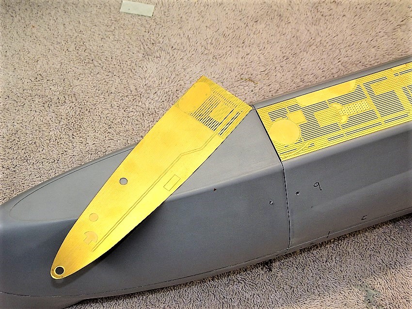
Here is what I came up with today.

The new part fits like a glove into the stern planes and the inner machined round journals ride smoothly in the bearings that come installed in the abs moldings. No more slop like the original part had. Small 1/16” pins secured in the aft plane supports will interface with the tubes at the outer ends of the planes.

Planes in the neutral position.

Up angle position.

And down angle position.

Nice and level across both planes.
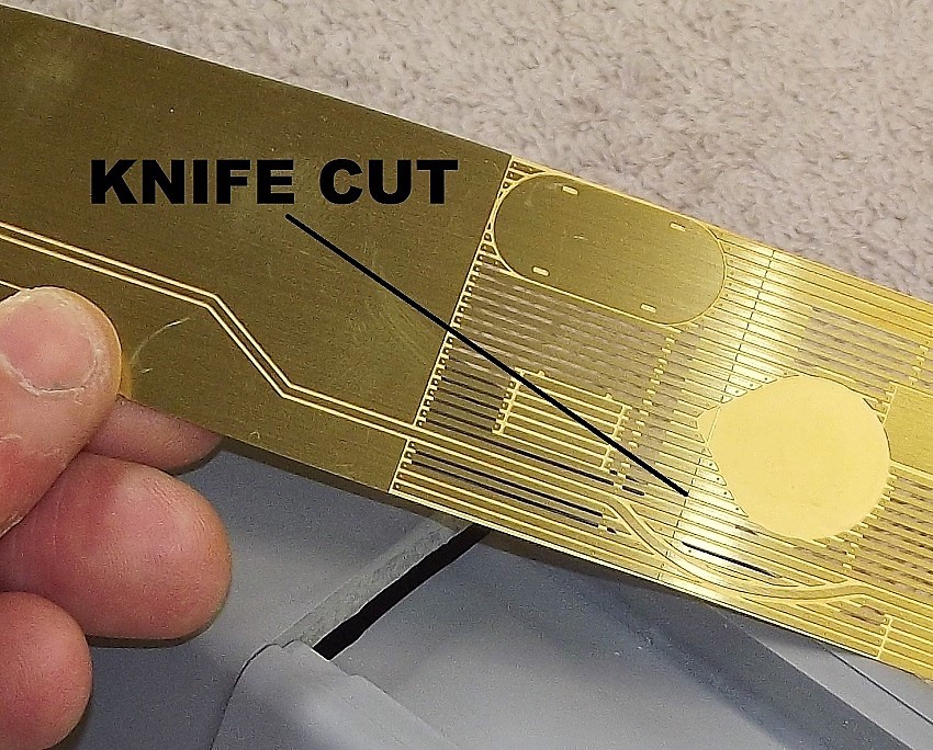
The gap between the two hull halves where the pushrod linkage will need to run to connect to the aft plane lever arm is .122” in width. Just a gnats ass under 1/8”.
The width of the lever arm is .031”. I’m considering using a very short length of .031” diameter wire bent into a typical Z bend to make the connection to the lever arm. This would give about .028” of space to work with after you add up the material thicknesses filling the .122” width slot in the hull. From the short piece of .031 wire I can quickly step the diameter up to 3/32” and then 1/8” once the pushrod travel clears the narrow slot. Or I can cheat a bit and reduce the thickness in the hull halves in this area to open up the slot and use larger diameter wire to start with for making the connection to the lever arm.
Well that is today’s summary of the small bit of work accomplished.
Nick
Decided instead to change the design and just move forward with a simpler design with materials that I had on hand.
Here is what I came up with today.
The new part fits like a glove into the stern planes and the inner machined round journals ride smoothly in the bearings that come installed in the abs moldings. No more slop like the original part had. Small 1/16” pins secured in the aft plane supports will interface with the tubes at the outer ends of the planes.
Planes in the neutral position.
Up angle position.
And down angle position.
Nice and level across both planes.
The gap between the two hull halves where the pushrod linkage will need to run to connect to the aft plane lever arm is .122” in width. Just a gnats ass under 1/8”.
The width of the lever arm is .031”. I’m considering using a very short length of .031” diameter wire bent into a typical Z bend to make the connection to the lever arm. This would give about .028” of space to work with after you add up the material thicknesses filling the .122” width slot in the hull. From the short piece of .031 wire I can quickly step the diameter up to 3/32” and then 1/8” once the pushrod travel clears the narrow slot. Or I can cheat a bit and reduce the thickness in the hull halves in this area to open up the slot and use larger diameter wire to start with for making the connection to the lever arm.
Well that is today’s summary of the small bit of work accomplished.
Nick
Attached Files


Comment