
An update on the SubDriver (SD) and 1/72 Type-23 model submarine it�s going into:
Since my last post I�ve indexed the SD within the hull; worked out the running gear between SD motor and propeller; and developing the linkages needed to position the stern planes and rudder.
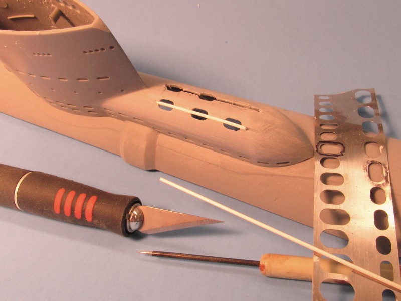
One major improvement, that has taken some time and ingenuity, during hull assembly, has been the incorporation of six practical limber hole/hand-grabs atop the diesel muffler fairing astern of the sail. As represented on the stock kit they are very shallow indentations � an artifact of the injection molding process, where sunken features cannot be adequately represented on tool cavities of deep draft.
Here you can see how I�ve dug open the oval openings and inserted a length of styrene square stock to form the hand-grabs that make these six limber holes unique from those on the hull and sail.
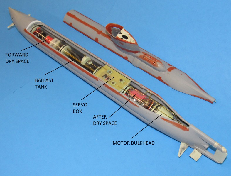
A single indexing pin within the hull engages a hole at the bottom of the SD�s ballast tank. This prevents any fore, aft, and rolling of the SD within the models hull. Without the pin it would be a constant battle adjusting the linkages as the SD slide within the hull. That done I addressed the running of the linkages pushrods to the control surfaces; and a preliminary look at how I would arrange the running gear.
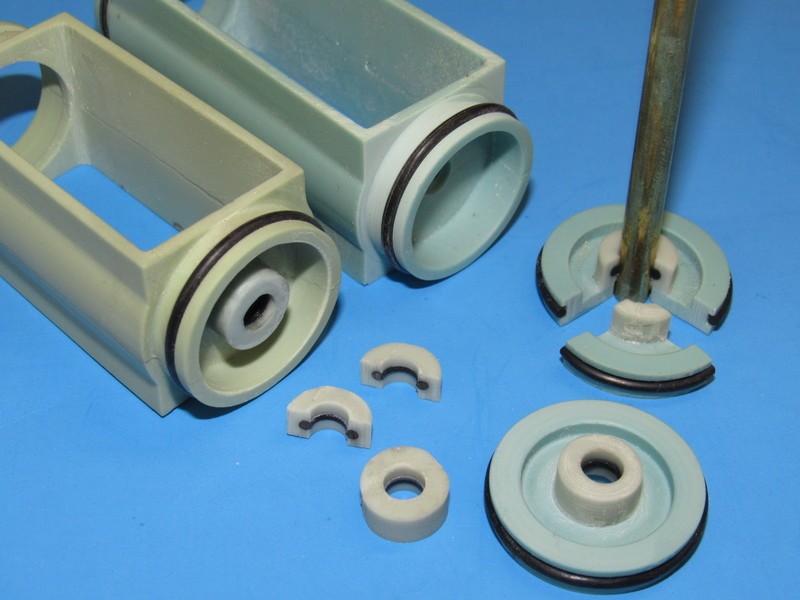
I�ve denoted the main spaces within this little 1.25� diameter SD. Of note is how I employed magnets to translate the motion of the internal servo output arms to the external pushrods. The ballast vent, rudder, and stern planes are positioned as a consequence of magnet motion atop the servo box.
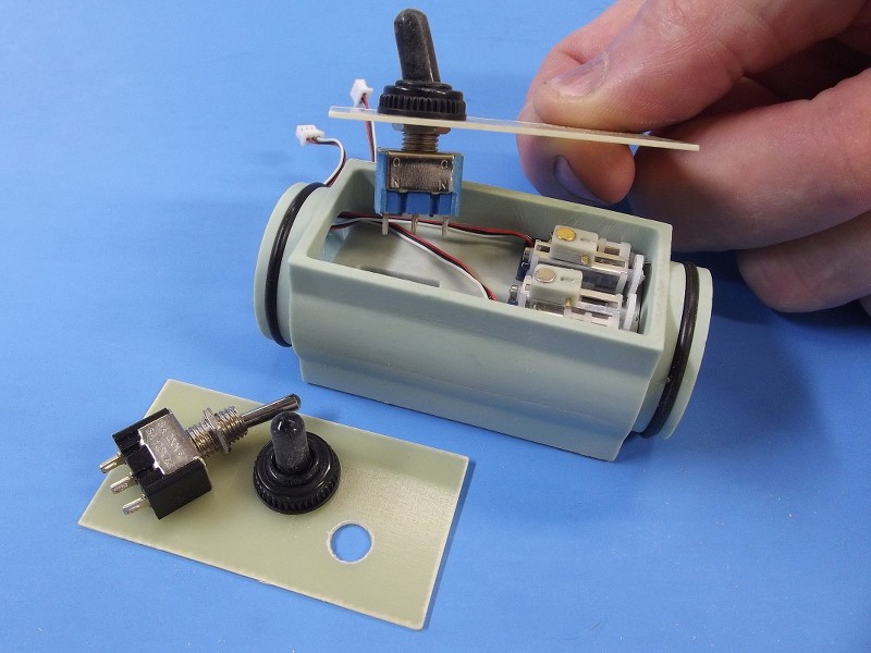
The servo box contains little, slightly modified linear motion servos (the kind used in those light weight indoor flying model aircraft). The shuttle/bell-crank of each servo has attached to it a magnet that is positioned under a thin fiberglass box-top. It�s the magnetic attraction between the inner and outer set of magnets that accomplishes the task of linking the internal (dry) magnet to the outer (wet) magnet, thus eliminating the need for any traditional pushrod seals.
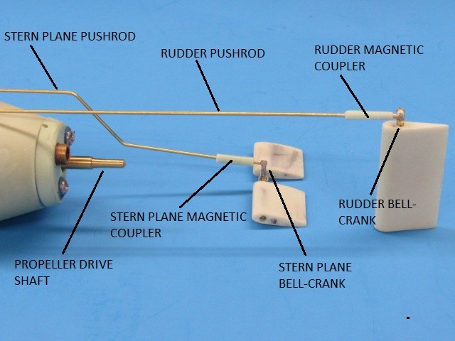
Illustrated below is an old-style arrangement. Today the toggle mission-switch has been replaced by a magnetically actuated electronic switch located in the forward dry space of the SD. Other than that, the servo box on the Type-23 SD is pretty much the same arrangement.
The right-angle bends at the forward ends of the pushrods are there to permit fine adjustments of pushrod length during set-up. The rudder pushrod runs through the hollow rudder upper skeg, and the stern plane pushrod is directed low engage that control surfaces bell-crank.
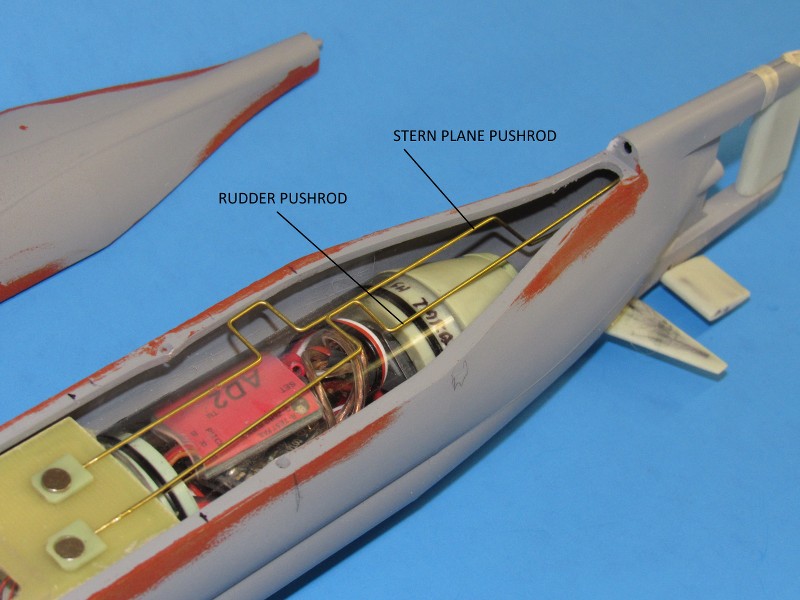
I was getting cute here: trying to keep the rudder linkage hidden within the upper skeg section of hull. No small feat on a model submarine this small.
This may, or may not work. My inspiration here is the magnificent work of Tom Chalfant and Manfred Reusing. Two masters of making very small r/c submarines work in a credible fashion. I blame both for this little slice of insanity!
Specifically I�m investigating the viability of using a magnet engaging an iron bell-crank element atop the rudders operating shaft as the means of translating the longitudinal motion of the pushrod to a rotation of the rudder. Unfortunately the short moment arm and relatively weak magnetic �pull� may not be enough here to hold up against the propeller flow forces acting on the rudder. If this does not pan out during �sea trials� I go old-school and run an external bell-crank to the rudder with a hard-and-fast mechanical union between externally running pushrod and bell-crank. We�ll see.
The stern planes are also connected through a magnet working an iron piece incorporated within the stern plane bell-crank.
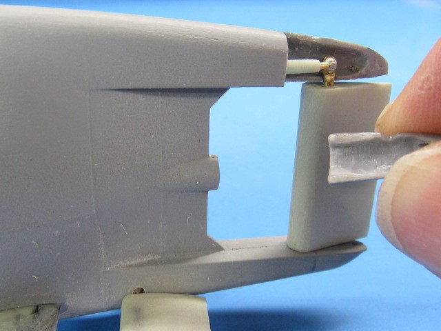
The little magnet engages an iron bell-crank. It�s as simple as that. I cut away a bit of the upper skeg to get access to the rudder bell-crank, but once I�m happy with the linkage I�ll permanently attach the removed piece and fair it in. In the event I find it better to go with a traditional hook-up between pushrod and rudder bell-crank I�ll simply pull the magnet equipped pushrod and replace it with a pushrod that will run externally to the rudder. Always have a fall-back position when drying something new.

Hopefully this mock-up will demonstrate to you how the magnets are used to connect the linkages in an almost non-kickback fashion.
I found that I only had room for a 13� long SD for this model. Just long enough to provide a ballast tank with enough floodable volume to produce the buoyancy needed to get the model up to designed waterline.

David
Since my last post I�ve indexed the SD within the hull; worked out the running gear between SD motor and propeller; and developing the linkages needed to position the stern planes and rudder.
One major improvement, that has taken some time and ingenuity, during hull assembly, has been the incorporation of six practical limber hole/hand-grabs atop the diesel muffler fairing astern of the sail. As represented on the stock kit they are very shallow indentations � an artifact of the injection molding process, where sunken features cannot be adequately represented on tool cavities of deep draft.
Here you can see how I�ve dug open the oval openings and inserted a length of styrene square stock to form the hand-grabs that make these six limber holes unique from those on the hull and sail.
A single indexing pin within the hull engages a hole at the bottom of the SD�s ballast tank. This prevents any fore, aft, and rolling of the SD within the models hull. Without the pin it would be a constant battle adjusting the linkages as the SD slide within the hull. That done I addressed the running of the linkages pushrods to the control surfaces; and a preliminary look at how I would arrange the running gear.
I�ve denoted the main spaces within this little 1.25� diameter SD. Of note is how I employed magnets to translate the motion of the internal servo output arms to the external pushrods. The ballast vent, rudder, and stern planes are positioned as a consequence of magnet motion atop the servo box.
The servo box contains little, slightly modified linear motion servos (the kind used in those light weight indoor flying model aircraft). The shuttle/bell-crank of each servo has attached to it a magnet that is positioned under a thin fiberglass box-top. It�s the magnetic attraction between the inner and outer set of magnets that accomplishes the task of linking the internal (dry) magnet to the outer (wet) magnet, thus eliminating the need for any traditional pushrod seals.
Illustrated below is an old-style arrangement. Today the toggle mission-switch has been replaced by a magnetically actuated electronic switch located in the forward dry space of the SD. Other than that, the servo box on the Type-23 SD is pretty much the same arrangement.
The right-angle bends at the forward ends of the pushrods are there to permit fine adjustments of pushrod length during set-up. The rudder pushrod runs through the hollow rudder upper skeg, and the stern plane pushrod is directed low engage that control surfaces bell-crank.
I was getting cute here: trying to keep the rudder linkage hidden within the upper skeg section of hull. No small feat on a model submarine this small.
This may, or may not work. My inspiration here is the magnificent work of Tom Chalfant and Manfred Reusing. Two masters of making very small r/c submarines work in a credible fashion. I blame both for this little slice of insanity!
Specifically I�m investigating the viability of using a magnet engaging an iron bell-crank element atop the rudders operating shaft as the means of translating the longitudinal motion of the pushrod to a rotation of the rudder. Unfortunately the short moment arm and relatively weak magnetic �pull� may not be enough here to hold up against the propeller flow forces acting on the rudder. If this does not pan out during �sea trials� I go old-school and run an external bell-crank to the rudder with a hard-and-fast mechanical union between externally running pushrod and bell-crank. We�ll see.
The stern planes are also connected through a magnet working an iron piece incorporated within the stern plane bell-crank.
The little magnet engages an iron bell-crank. It�s as simple as that. I cut away a bit of the upper skeg to get access to the rudder bell-crank, but once I�m happy with the linkage I�ll permanently attach the removed piece and fair it in. In the event I find it better to go with a traditional hook-up between pushrod and rudder bell-crank I�ll simply pull the magnet equipped pushrod and replace it with a pushrod that will run externally to the rudder. Always have a fall-back position when drying something new.
Hopefully this mock-up will demonstrate to you how the magnets are used to connect the linkages in an almost non-kickback fashion.
I found that I only had room for a 13� long SD for this model. Just long enough to provide a ballast tank with enough floodable volume to produce the buoyancy needed to get the model up to designed waterline.
David


Comment