Neat! End product or master pre-casting?
J�rg
-
The end caps of the ballast tank are ready... Perhaps my reasoning behind making a custom water pump did not make sense. Routing the tubing inside is tricky, as the minimum bending radius of the tubing is relatively large. The last picture shows that both the discharge and suction of the pump and the lines integrated in the intermediate cap are in line. This was my aim; this way, no bending of the tubes is required. It will only require a small straight piece of tubing.
Grtz,
Bart
Leave a comment:
-
-
-
The WTC pushrod seals are also ongoing. I wanted to use bellows, so I tried to manufacture them myself; however, all attempts failed. The bushings in the endcap are 8mm while the pushrods will be 2mm.
The first method I tried involved using flexible resin. Although they looked good, the flexibility was not as expected, even though the wall thickness is only 0.5mm. They can be squeezed between two fingers, but it would challenge the servos. The fatigue test was not good; they broke after being bent a few times."
Then I came up with the idea to cast them out of silicone rubber (mold making rubber). I made a two-part mold with a core. The first attempt failed because the rubber deep inside the mold refused to cure. In subsequent attempts, I placed the mold in an oven with the idea of aiding the curing process, but that didn't work either. From the pictures, it can be seen that deeper in the mold, the curing of the silicone stopped. In my opinion, this was due to the lack of silicone mass to facilitate curing. At the bottom of the mold, the silicone is cured, as the body mass is higher.
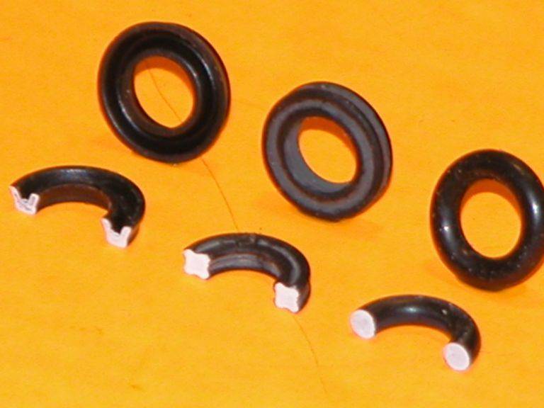
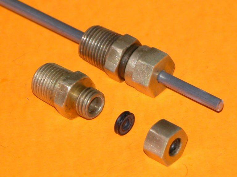
Then I decided to use O-rings. The bushings in the endcap would come with threads, and an endcap would be used to secure and squeeze the O-ring. Initially, I went for a fine 0.5mm pitch thread. That did not work out, as the threads did not align properly and were damaged when forced.
I abandoned the idea of using a fine thread and instead applied a pitch of 1.25mm. The standard thread did not work, so I started applying a larger clearance between the endcap and the bushing. Both bushings and endcaps were marked with the applied clearance to keep them identified. An additional clearance of 0.05mm seems to hit the sweet spot.
Difference between the 0.5mm and 1.25mm pitch
Different attempts one fail and two wins.
Again o-rings are on order to carry out some testing.
Grtz,
BartLeave a comment:
-
-
Backflow, yes as expected. I hope I can eliminate this by raising the suction/discharge line to the ballast tank above the water level in surfaced condition; otherwise, I have to use a solenoid (preferably not). Regarding pressure, it required quite some effort to stop the flow by applying pressure with my finger on the discharge. I can't do it without taking a small shower.
Grtz,
Bart
Leave a comment:
-
Bart, that rocks. Solid design ideas!
I could use something like this in my 1/144 Seawolf sub.
Leave a comment:
-
That is one well designed, kick-ass little gear pump, pal. Well done sir! The GPM is outstanding. Much backflow when stopped and the backside has a significant pressure over the front end?
Consider going commercial with this thing, Bart.
You European's are an amazing bunch.
DavidLeave a comment:
-
The O-ring has arrived and fits perfectly. There were no leaks during the test run. Results at 3500 rpm show a flow rate of 1.2 liters per minute or 40.6 fluid ounces per minute.
Grtz,
Bart
Leave a comment:
-
While awaiting the arrival of the O-rings, I assume the come by pigeony, I designed a gearbox for the pump. This design keeps everything compact, ensuring that the motor's outline fits snugly within the pump's perimeter. A bearing was installed on the pump side, and Teflon washers were utilized to provide clearance between the moving and stationary parts. These washers, originally 1mm thick, were sanded down to 0.5mm for. Despite its small size, the gearbox is provided with openings to facilitate assembly. Additionally, Locktite was applied to the set screws of the gears.
Grtz,
Bart
Leave a comment:
-
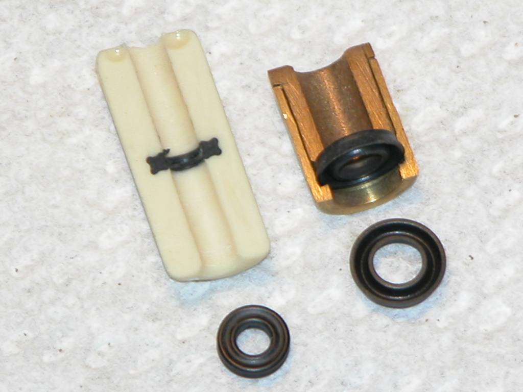
Assembling the pump. Tolerances were still good after fully curing.
Lip seal and bushing were pressed in place using the drill press.
The bushing and gears had an overlength to allow machining to the correct length. For the gears, I used a brass tube with the correct ID to hold the gear so I could secure it in the chuck of the lathe.
Both pump housing and cover are secured together using stainless steel M3 bolts.
Waiting for the arrival of the O-rings for a test run.
Grtz,
Bart
Leave a comment:
-
-
Wow! Thats so interesting. Using the Archimedes' principle, how does the 310 grams weight you registered translate into ballast tank volume according to your calculations?Last edited by Albacore 569; 04-29-2024, 12:50 PM.Leave a comment:
-
I've been occupied with the design of the WTC.
To determine the minimum lifting capacity of the WTC, I measured the weight of the hull above the waterline when surfaced. As with my AKULA, I used Archimedes' principle, calculating the difference in weight between when the vessel is surfaced and when it's submerged. I determined that a minimum of 310 grams is required.
Measuring setup.
After several prototyping runs, I realized I had a massive oversight regarding the pumps.
I ordered a water pump and, upon testing it, discovered it was a one-way pump, not reversible. I decided to use two pumps instead and adjusted the design accordingly. The pumps would rest in cradles, and "sea" suction and overboard functions were integrated into the intermediate cap, which acted as the bulkhead for the ballast tank. I was quite proud of the design until I realized that the pumps were "open," meaning they allowed water to flow freely without running. This oversight felt rather foolish and embarrassing, to be honest.
I abandoned the idea of using two pumps and sought a reversible gear pump. In the past, cars on this side of the pond used windshield washer pumps from the brand VDO, which were gear pumps. I know that a gear pump also backflows when there's a pressure difference, but I pondered providing a loop above the water surface level to mitigate this.
I couldn't find a suitable mini gear pump, and the VDO pumps are hard to come by. Furthermore, I wanted a brushless motor to drive the pump. So, I decided to design one myself. I'm not sure how well it will work, but it was a fun challenge. I'll use 4mm shafts, as I use them wherever possible. I buy 3m lengths of this material, and I have seals and bushings in my standard stock for the 4mm shafts.
For the seal between the cover and the housing, I used an O-ring. O-rings can be used in rectangular or non-circular groove patterns, but it's important to consider the minimal bending radius, which should be at least 6 times the circumference of the O-ring. I calculated the required ID of the O-ring by converting the circumference of the rectangle to a diameter. The inlet and outlet are part of the cover and will face towards the intermediate cap of the ballast tank (which I will redesign).
The prototype needs to settle for a few days to allow shrinkage to occur. The clearances and gear backlash seem okay at first glance, but further settling is necessary. Any design flaws or weak spots will be revealed after conducting a test run.
Below is a rendering of the WTC designed for two pumps.
Servo rack (Yellow)
Pump Saddles (red), now obsolete
Ballast tk, inside I provided a fairly large conduit for the cables (silver)
Several prototypes have been made and adapted to overcome issues.
Servo rack
Encap
Pup racks (now obsolete)
Grtz,
BartLeave a comment:


Leave a comment: