Scratch Build Project 955 Borei K-535 "Yuri Dolgoruki" SSBN. 1/140 Scale.

Collapse
X
 
  • Time
  • Show
Clear All
new posts
  • Davidh
    Captain
    • Nov 2010
    • 719

    #91
    Click image for larger version  Name:	IMG_4336[1].JPG Views:	1 Size:	13.7 KB ID:	121454
    Click image for larger version  Name:	IMG_4340[1].JPG Views:	1 Size:	13.7 KB ID:	121455
    Click image for larger version  Name:	IMG_4339[1].JPG Views:	1 Size:	13.2 KB ID:	121456
    Click image for larger version  Name:	IMG_4348[1].JPG Views:	1 Size:	14.8 KB ID:	121457
    Click image for larger version  Name:	IMG_4347[1].JPG Views:	1 Size:	13.3 KB ID:	121458
    Click image for larger version  Name:	IMG_4337[1].JPG Views:	1 Size:	13.1 KB ID:	121459
    Hello All,

    Finished work today, I am now officially on long service leave, a week here in Oz before getting on that big petrol budgie and heading off to Europe....

    Last week I mentioned getting the Hull prepped for mounting on the board ready to mould. Before moving I carefully wrapped up Dolgoruki in a blanket and packing taped around it of the move to our new house. When I unpacked it a couple of weeks ago I noticed some small cracks occurring along the hull mainly where wood and PVC pipe mixed and interacted. I have put it down to expansion and contraction differences in material. Also we have moved closer to a lake which is only about 200 metres down the road so there may be humidity involved as well.

    I will spend this week going over the cracks and rectifying them so that the hull is as smooth as a babies bum. I will then finish off any further scribing that is needed so that when I get back I should be able to pretty much get into the hull mould creation. RTV silicon rubber mould with a fibreglass hardback. In order to reduce the cracking from occurring I will then bag up the hull in garbage bags taped down really well and placed in an area of the Garage with the least amount of temperature change over the next six weeks, fingers crossed.....

    Last week I found a nice big table top that wasn't being used and was just the right length to use as a moulding board. I cut it up to the right length and width then cut some side and end pieces to reinforce and strengthen the board and most importantly make sure it stayed absolutely flat. Once this is done I would measure a line down the centre and align the hull on the centre whilst then drawing an outline of the hull to cut out. I spent a fair bit of time getting the profile just right before I was confident that I could now cut out the shape with a jigsaw.

    I took a big drill bit and drilled a couple of holes inside the perimeter of the cut out area and then started with the jigsaw. Outside my new workshop is a small bench originally designed for putting the washing basket on , it has an outside power point and is perfect for this kind of work. Clamping down the board and get started.

    Once the shape had been cut it was simply a case of seeing how the model fit inside the cut out and whether the hull would sit easily down at the waterline half way. I had to get a rasp and grind away some areas around the stern, but soon enough it was a good fit.

    Taking some countersunk self tapping screws and drilling pilot holes around the sides of the board allowed me to then attach the side boards and then the end pieces. At this stage there was no support underneath the hull so that It would simply fall through. I would then cut out two square inserts that would fit in underneath the hull and featured a semi circle cut out to rest the underside hull at just the right level so that the waterline was precisely level with the top of the board.

    This whole construction is laminated MDF board so it runs the risk of sucking in moisture over the time I am away, so I am also thinking of bagging this structure as much as possible to reduce swelling and warping. Once again fingers crossed...


    Till next Friday, last instalment. I'm hoping that the next sub I see will be the Vesikko in Finland.

    David H
    Last edited by Davidh; 05-05-2017, 06:56 AM.

    Comment

    • Davidh
      Captain
      • Nov 2010
      • 719

      #92
      Hello All,


      What do you get when people don't know what you want for birthdays and Christmases? Gift cards. I had an accumulation of gift cards from last year, all from Bunnings. (Bunnings is a big Hardware chain here in Oz like Home Depot in the US). Soon I had enough for a decent 2 H p compressor. I had been wanting to get one of these for a while as after doing some homework I decided to give pressure casting a go. I asked a colleague at work If I could borrow his spray paint pressure pot. This week I had the opportunity to give it a try.

      I have been pouring Polyurethane castings for a couple of years now and its been a bit hit and miss, knowing that I really needed to do something about air bubbles because as you work your way through the bottle your get an increase in bubbles, (probably an accumulation after slowly being exposed to atmosphere.) which means that your first castings from the bottle are ok. by the bottom they suck.

      So I open up the pot, turned on the compressor to get some air ready and poured the resin into the mould. then I placed the moulds inside the pressure pot and screwed down the four clamps. I then turned the gauge to get some pressure and watch the needle rise to around 30 psi. About 1 hour later I came back and released the air. The unclamped the four sides and pulled the moulds out.

      The resin what hard but what would the mould be like? I pulled off the silicon mould and saw that all the parts had VIRTUALLY NO BUBBLES!! I have since done a couple more batches and they have all turned out virtually bubble free.

      There is a picture of the Dolguruki prop, one before pressure casting and the other, after.

      For a long time I have put though into an issue that I had with the Resolution mould. The Resolution class SSBN has like all SSBN's a flat missile deck. I use a flexible silicon mould for creating the top mould hull half. For this I used my usual silicon and a fibreglass hardback. After pulling a few top hull moulds It came to my attention that getting a flat missile deck to remain flat in a silicon mould is a real challenge. If the silicon mould is not laid just right in the hardback then you will get slight undulations in the resultant layup and even the most subtle flat surface that ain't flat is noticeable.

      For months I thought about ways to stiffen the missile deck in such a way as to as close as possible to guarantee that the deck will be flat in an otherwise wobbly mould. After thinking through some Ideas I decided the really stiff security screen mesh might just do the job. This mesh is a stiff matrix of wire that would easily allow the silicon to infuse and mix through the individual strands of wire. I cut a strip, this stuff is hard to cut! I cut a length just a little wider than the wides of the missile deck so that I could wrap around the edges, thus increasing the stiffness even further. The wire strip extends from the back of the missile deck and continues a little further beyond the sail and then stops. The idea being that it will only stiffen and keep flat the missile deck and the forward flat deck. The sides of the top hull will be flexible. I will lay down a thick coating of silicon over the top hull. Then once dried will lay down another layer of silicon then press the mesh down and lay up another layer of silicon over the mesh till its completely enclosed.

      What do you think David?
      Comments please.

      David H Click image for larger version

Name:	IMG_4501.JPG
Views:	93
Size:	17.3 KB
ID:	121584Click image for larger version

Name:	IMG_4496.JPG
Views:	82
Size:	13.2 KB
ID:	121585Click image for larger version

Name:	IMG_4497.JPG
Views:	83
Size:	14.4 KB
ID:	121586Click image for larger version

Name:	IMG_4499.JPG
Views:	97
Size:	14.8 KB
ID:	121587Click image for larger version

Name:	IMG_4488.JPG
Views:	80
Size:	14.9 KB
ID:	121588
      Click image for larger version

Name:	IMG_4495.JPG
Views:	78
Size:	7.1 KB
ID:	121589

      Comment

      • He Who Shall Not Be Named
        Moderator
        • Aug 2008
        • 12320

        #93
        I think you're approaching the anti-creep situation from the wrong direction: you don't stiffen the rubber element; you insure a positive keying network between the rubber glove and the GRP mother-mold. You work into the rubbers outer surface a rough and ridged network that indexes the rubber to the GRP. Like so:


        David
        Who is John Galt?

        Comment

        • steveuk
          Ensign
          • Apr 2017
          • 20

          #94
          Great progress on this! It was really nice meeting you Dave. I have to say from reading this write up, Dave M's glove mould (the soft part) above looks to be thick and substantial, like it retains some stability of its own, not relying completely on the fiberglass backing. Yours seem thinner and floppier? This could be why your glove mould fails to sit properly flat over your flat deck areas. Just my opinion for what it's worth cuz I know you are still thinking about adding the metal mesh inside the silicone layer. One last thing - I can't think of seeing any one else use rigid mesh inside the silicone glove moulds, and I've seen some pretty large glove moulds, eg ILM Enterprise D saucer section was huge! Just putting that out there.

          Comment

          • Davidh
            Captain
            • Nov 2010
            • 719

            #95
            Hello All,

            Well I back from my European Trip cunningly disguised as an excuse to visit lots of subs.

            Had a great time and managed to Visit Vesikko in Helsinki, Neptun in Karlskrona and an impromptu Telephoto moment with a Vastergotland class Boat at the Dock in Karlskrona. (Just ignore the signs saying military area, no Photography allowed...) And finally another Telephoto lens moment on the hills above, Rosyth , Scotland, yes after years of trying I finally got some long range shots of all four Resolution class SSBN's !!

            Back home in OZ with the Dolgoruki sitting in it's mould box ready to go. As mentioned before I did not want to start the mould process before I left and leave the process half down for 6 weeks and worry about expansion and contraction and all that. I bagged up the master before leaving because I didn't know if there could be warping and cracking. I put the model under the bench so that it would not be subjected to sun cycles on one side, and would see if there was any movement in the model when I got back.

            As it turned out there was none. The model had handled the slow transition to winter rather well. As for me I felt like I mostly took winter with me. It was only in the last week of the trip when I was in Ireland that it got up to a blistering 26 degrees and some of the locals were taking their shirts off.

            Once Dolgoruki was where I wanted her it was a case of taking of the wooden side walls (to hold in the silicon) and then squash clay around the edges to make a smooth surface right up to the model and the mould board. Once this was done I simply had to screw the thin silicon retaining walls around the perimeter of the model and she would pretty much be ready for laying up the first silicon layer.

            I decided initially to mix up some Silastic and pour it around the base of the model in between the sides of the model and the wooden retaining wall that was there to give a nice continuous edge. I made this batch and kept it runny so that it would fill the void easily. I then mixed the next batch and added some thixotropic agent to thicken it up so that it would cling to the sides of the hull and over the top of the hull. This first layer would be relatively thin as to allow bubbles to escape and so I could see how the initial layer would lay down. I waited till next day for it to dry and then mixed another batch to pour over the top.

            after this layer had dried I then thickened up another layer and pasted it on. These layers having a thixo mix to thicken it up. I then took the mesh that I had bent to the right shape and smothered some more silicon over and under this. It being really important that were was enough silicon mix underneath and around the mesh. I have had lots of time to think over this decision and have spoken to several people about whether this approach would work. All I can say is that It may be a failure or it may work O.K or it may work really well. If I can get really smooth consistent and flat missile decks I will be happy.

            Finally after the mesh has been pressed down and in to the mix a final layer of silicon over the top. I did have to check that there was enough silicon under the mesh and make sure that it was properly supported. I also had to thicken up this layer so that the Fibreglass hardback would register as effectively as possible to keep the silicon in place and in shape.

            Until later....


            Click image for larger version

Name:	IMG_4627.JPG
Views:	127
Size:	16.3 KB
ID:	122101Click image for larger version

Name:	IMG_4628.JPG
Views:	83
Size:	14.3 KB
ID:	122102Click image for larger version

Name:	IMG_4518.JPG
Views:	85
Size:	14.4 KB
ID:	122103Click image for larger version

Name:	IMG_4517.JPG
Views:	90
Size:	14.6 KB
ID:	122104Click image for larger version

Name:	IMG_4517.JPG
Views:	81
Size:	14.6 KB
ID:	122110Click image for larger version

Name:	IMG_4632.JPG
Views:	79
Size:	11.1 KB
ID:	122105Click image for larger version

Name:	IMG_4638.JPG
Views:	76
Size:	12.9 KB
ID:	122106Click image for larger version

Name:	IMG_4642.JPG
Views:	85
Size:	18.9 KB
ID:	122107Click image for larger version

Name:	IMG_4629.JPG
Views:	87
Size:	16.9 KB
ID:	122108Click image for larger version

Name:	IMG_4630.JPG
Views:	89
Size:	17.2 KB
ID:	122109Click image for larger version

Name:	IMG_4517.JPG
Views:	90
Size:	14.6 KB
ID:	122111Click image for larger version

Name:	IMG_4639.JPG
Views:	87
Size:	17.0 KB
ID:	122112Click image for larger version

Name:	IMG_4643.JPG
Views:	84
Size:	15.7 KB
ID:	122113Click image for larger version

Name:	IMG_4645.JPG
Views:	85
Size:	12.5 KB
ID:	122114Click image for larger version

Name:	IMG_4650.JPG
Views:	83
Size:	14.1 KB
ID:	122115Click image for larger version

Name:	_DSC5910.JPG
Views:	88
Size:	16.1 KB
ID:	122116Click image for larger version

Name:	_DSC5909.JPG
Views:	81
Size:	14.6 KB
ID:	122117Click image for larger version

Name:	_DSC6541.JPG
Views:	95
Size:	21.1 KB
ID:	122118Click image for larger version

Name:	_DSC6305.JPG
Views:	87
Size:	18.2 KB
ID:	122119Click image for larger version

Name:	_DSC6267.JPG
Views:	74
Size:	20.0 KB
ID:	122120

            .

            Comment

            • steveuk
              Ensign
              • Apr 2017
              • 20

              #96
              Hi Dave, did you get the Dolgoruki ref pics I sent through ok and were they what you were searching for?

              Comment

              • Davidh
                Captain
                • Nov 2010
                • 719

                #97
                Hi Steve, no I haven't seen anything new from you. Did you send some more pics. Will look forward to seeing them


                dave

                Comment

                • steveuk
                  Ensign
                  • Apr 2017
                  • 20

                  #98
                  Yes. I found your emblem artwork for Dolgoruki !! I will send a new email with what I found cuz it is nice large size...

                  Comment

                  • Davidh
                    Captain
                    • Nov 2010
                    • 719

                    #99
                    Hello All,

                    It's been a busy week and fortunately the weather has been kind, although winter our weather here on the East coast of Oz is pretty mild. We have been getting midday temps approaching 20 degrees C. Good enough for fibre glassing with a little extra hardener.

                    So after a couple of coats of Silicon, had to make an extra trip to the supplier up in Newcastle, about an hours drive. Wanted to make sure that this glove mould is thick enough. I do not want any tares. I was now ready for the Fibreglass hard back. I have allocated different colours for the silicon moulds I do for each kit but when it comes to the hull silicon mould I simply keep it white. However the hardback will be my standard orange colour that I have always been using so after mixing up a batch of Resin and adding some orange pigment, it would be time to add some talc to thicken in up into a paste. It amazing how much talc that the resin actually takes to make it thicken up enough. I wanted to make sure that the resin that I mixed on the sides of the silicon mould would stick and simply not run down to the bottom. I would have to work this layer a little bit as it needed to really work in to the thickened and roughed up surface of the silicon as the last layer is the keying layer needed to maintain rigid shape of the silicon once using the moulds. This should also be aided I hope by the rigid mesh embedded deep in the silicon.

                    Once the first layer of resin hard hardened I then started laying down some chopped strand. Many years ago a colleague at work, who used to be a surfboard shaper and gave it up to be a teacher, gave me what was left of his fibreglass stock. This included a massive reel of fibreglass strand. This reel weighed a ton and 10 years later still doesn't look much depleted. I simply pull a small length and chop with scissors into a bin. Do this long enough and you have all the chopped strand you could need. So I liberally apply this chopped strand. Looks like a dogs breakfast but does the job. It does not need to look pretty it just needs to be strong and hold the shape of the silicon. I also took some long lengths of the strand and applied it around the base where the sides of the hull meed the flat and apply this to reinforce an area that could be weaker.

                    After this is done and there are several layers of glass over the silicon a hardback can be applied. This "egg-crating" as Mr Jorgensen calls it is an important reinforcing element. Years ago I did some wing moulds and didn't reinforce them properly. I was foolish enough to leave them out in the sun on a November day. 30C and they were very badly warped. So for these moulds sheet 3 ply is used. I cut some lengths about 100mm wide and then four profiles to distance the two sides. This effectively creates a crate type set up that once glassed down and along the sides ensures that the moulds will not dare warp. It also makes a nice sturdy rest for the moulds as you are laying up.

                    The mould being laid up next to the orange mess is a lower hull half of a Mike. Gives you a size comparison. Dolgoruki is big, at 1/140th scale is will just fit across the backseat of my Corolla. This boat is as big and the Ohio.

                    Enough for Now,

                    Enjoy...


                    Click image for larger version

Name:	IMG_4653.JPG
Views:	87
Size:	19.0 KB
ID:	122148Click image for larger version

Name:	IMG_4655.JPG
Views:	87
Size:	12.5 KB
ID:	122149Click image for larger version

Name:	IMG_4657.JPG
Views:	83
Size:	17.4 KB
ID:	122150Click image for larger version

Name:	IMG_4659.JPG
Views:	89
Size:	9.5 KB
ID:	122151Click image for larger version

Name:	IMG_4660.JPG
Views:	82
Size:	19.0 KB
ID:	122152Click image for larger version

Name:	IMG_4661.JPG
Views:	83
Size:	13.5 KB
ID:	122153Click image for larger version

Name:	IMG_4667.JPG
Views:	84
Size:	17.5 KB
ID:	122154

                    Comment

                    • Davidh
                      Captain
                      • Nov 2010
                      • 719

                      Hello all,

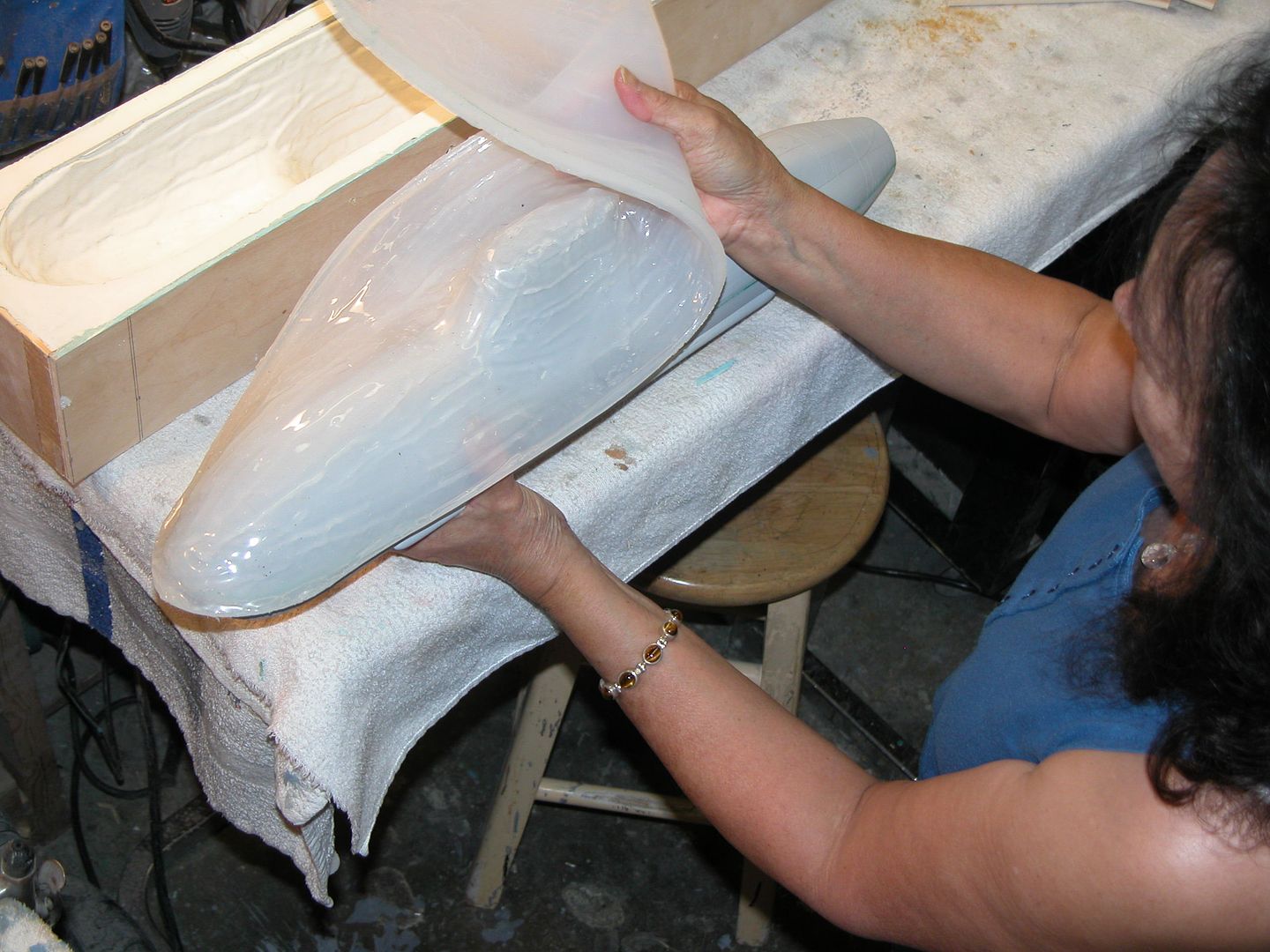
                      It's been a busy week. The top half of the mould being completed means that its time to turn over the mould and get on with doing the bottom half of the boat. Once the egg crating has hardened and the mould as such is fully dried it is time to turn it over and split the top mould off the board. This is usually pretty easy to accomplish and simply relies on a knife being run around the middle of the mould between the layer of fibreglass that has set against the veneered particle board. There is the concern that you don's pull the master out of the silicon mould above as you are doing this however the grip between the silicon and the master is usually pretty strong and I have never had a problem with this.

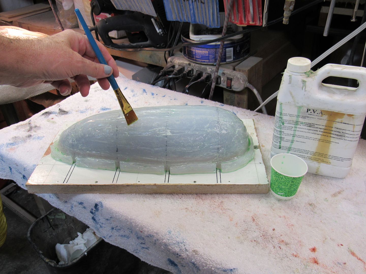
                      Once this top mould was pulled off then I could examine the mould and see how the hardback and silicon mould within fared. The silicon mould certainly looked cured and there was no pull of the silicon on release against the veneer board. I had to then trim and pull away the plasticine that filled the gap between the master and the cut out in the veneer that the hull rested in. the very edges of the fibreglass hardback are rough and you could easily cut your fingers so a good hard sand back to make a reasonably smooth edge and one that was not sharp would be in order. Once this was done I simply had to apply a few layers of release agent in the form of PVA around the fibreglass flange and over the master for the layup of the lower half.

                      Once the release agent had been applied I simply needed to put down my first layer of Gel coat. This would be thick and would need to set really well before applying a layer of resin and then several layers f glass to reinforce this layer. I initially layere d up a layer of 10 oz weave just to set a glass layer that would really adhere to the initial gelcoat and then I used a heap of the chopped strand that I have been making from the massive bundle that I have. I layered up a good couple of layers of this stuff and had it very where. I also would lay a long strip of it around the base where the resin changes direction as it comes down the side of the hull and then needs to go horizontal as it runs above the top mould flange.

                      Once this was done and hardened I would simply repeat the egg crating process, by fixing up a frame around the length of the mould and gluing it down to stop warping and distortion in the mould. By this stage the whole arrangement was getting seriously heavy and very solid. Two weeks worth of work and a lot of Silicon, fibreglass, resin and plywood all for a result you wouldn't be able to see until it was way too late to do anything about if there were a problem....

                      Once all your moulds have hardened and your master hull is completely enclosed in a fibreglass and silicon sarcophagus, it is then time to set it free and hope that all your effort in material, late nights, complaints from the wife about 'do you have to use that stinky stuff again?' and sticky fingers have paid off with a set of two moulds that will do the job, again and again... fingers crossed......

                      Prying the two halves apart ain't easy. Ideally I wanted the bottom mould to come off clean and leave the top of the mould with the silicon internal mould intact and not pulling out of its hardback. Easier said than done. I carefully ran the knife around the edge somewhere along two flanges dong their very best to look like one, but knowing that they are actually separate. I found a weak point and soon enough had the knife running along the fine line that was created by the release agent. Ideally plastic wedges or wooden ones as was the case were used. You want to try and avoid metal ones as they will scrape the fibreglass surface and mark it. I would knock the wooden blocks around with a mallet and gradually pull the two halves apart. It became clear however, pretty early on that the Silicon mould was starting to lift and that the master would most likely come out of the silicon half first before the fibreglass lower half. Oh well,

                      Stay tuned....


                      David H


                      Click image for larger version

Name:	IMG_4673.JPG
Views:	84
Size:	16.8 KB
ID:	122245Click image for larger version

Name:	IMG_4674.JPG
Views:	84
Size:	16.7 KB
ID:	122246Click image for larger version

Name:	IMG_4671.JPG
Views:	76
Size:	12.3 KB
ID:	122247Click image for larger version

Name:	IMG_4672.JPG
Views:	81
Size:	13.2 KB
ID:	122248Click image for larger version

Name:	IMG_4698.JPG
Views:	81
Size:	17.1 KB
ID:	122249Click image for larger version

Name:	IMG_4699.JPG
Views:	78
Size:	11.5 KB
ID:	122250Click image for larger version

Name:	IMG_4701.JPG
Views:	76
Size:	10.6 KB
ID:	122251

                      Click image for larger version

Name:	IMG_4702.JPG
Views:	78
Size:	11.4 KB
ID:	122252
                      Attached Files

                      Comment

                      • Davidh
                        Captain
                        • Nov 2010
                        • 719

                        Hello All,

                        Back into the Grind of school and having to go from zero to 100 kms in no time. My brain hurts...

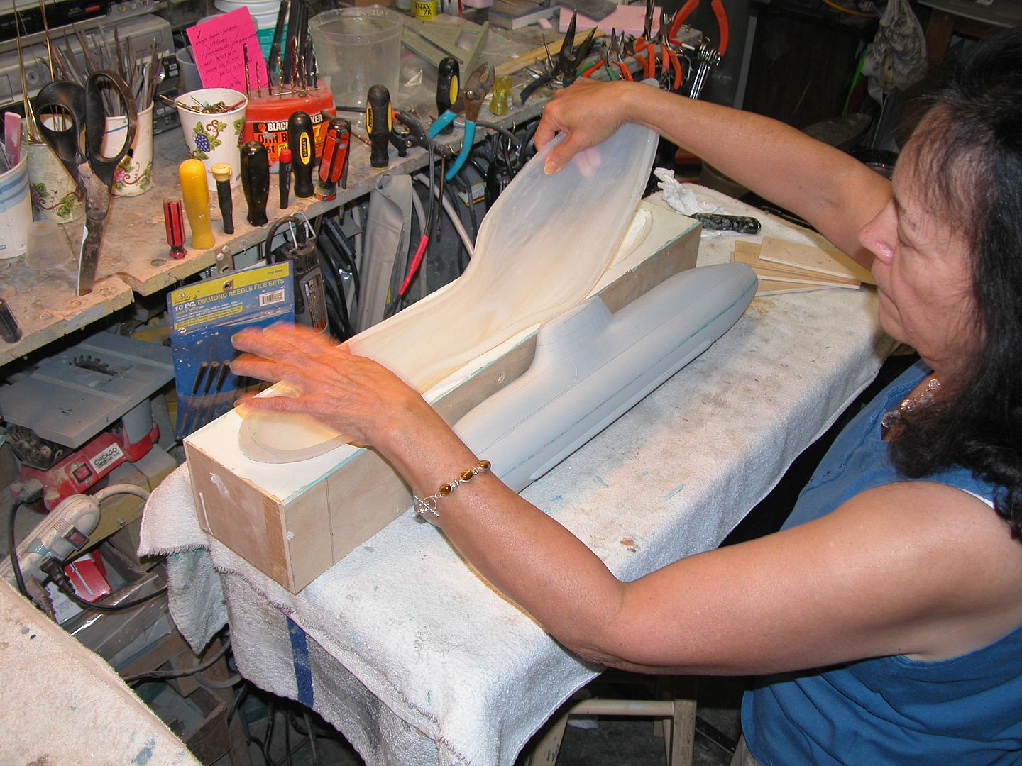
                        Anyway, the pull.. I ran wooden shims around the parting flange of the two parts and continued to pry the two halves apart. I cut a slight angle on the leading edge of the wooden shims in an effort to ride over the top of the rim of the silicon as it was pulling up in an effort to deflect it downwards back in to the mould and increase the distance between the silicon mould hardback half and the lower hull that is just a hard shell. This was succeeding to some extend however it still became pretty clear that the top silicon half was going to separate firstly from the master leaving the fibreglass lower half still on the master. The egg crating is also really crucial here, I have in the past deformed whole moulds that simply weren't up the stresses of the initial pull. The egg crating allows the whole mould to pull off once that critical point is reached when the whole master/ mould arrangement is about to give way.

                        The Top half pulled away from the master and the silicon mould partially came out of the hardback. As it pulled away you could easily feel how the section of the silicon mould with the mesh embedded was behaving. It was reluctant to pull out of the hardback. This came as no surprise as the rigidity afforded this section of the silicon also helped to make this part of the mould grip up against the hardback. This is probably partially due to the slightly negative draft angle of the silicon mould hardback combination.

                        I took a good amount of time inspecting the silicon mould and the surface condition of the mould. I was pleased to see that there were not air bubbles caused by gas build up in the silicon whilst pouring and certainly vindicates the reason to pour a thin layer first then followed by a couple more. The air bubbles result in blobs of resin on the finished part that simply creates more post de-moulding work for me.

                        A concern that I had with the silicon layup was one that emerged when I was embedding the mesh. The mesh piece that I had was actually at one point noticeably wider than the master and when embedding the silicon I was unsure as to whether there was enough silicon underneath the wire at one point to support it and make sure that there would be no sag or air pocket that could cause problems during the lay up of parts later.

                        There was an area around where the sail sits on the hull just down the side of the raised deck where the silicon has caused a dimple, I'm sure created by just this scenario. This undulation however could also be cause by the fact that the silicon mould is not sitting exactly even in the hardback and so this could be causing slight undulations in the silicon part that could be causing this. I have had no tears as was the case with the 'Komsomolets' and although there are one or two places where the silicon is a little thin, not too thin..

                        Where the mould is rigid it is really noticeable as can be seen in the photo. the missile deck ,rear deck and forward decks are, really flat there is no undulation. They are level and the silicon mould because of this rally presses down well in the hardback.

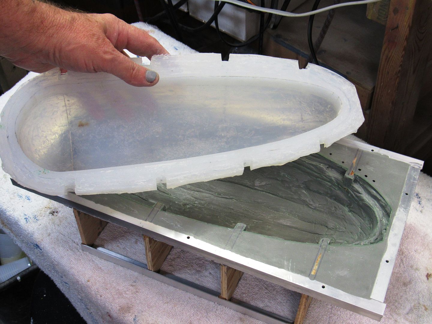
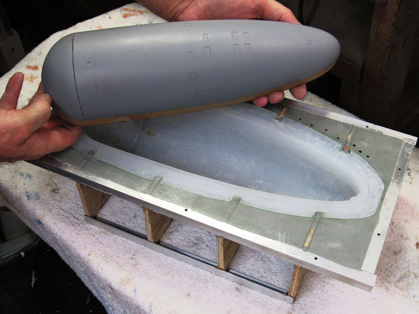
                        After this I started to pull the master out of the lower mould which is all fibreglass. This would require plastic shims and lots of prying. I would lever the back end of the master up and try and slip an long strip of plastic underneath the back of the hull and move it forward to break the surface tension and lift the master hull out of the mould. You have to be careful as you could easily damage the detail in the mould if you ain't careful.

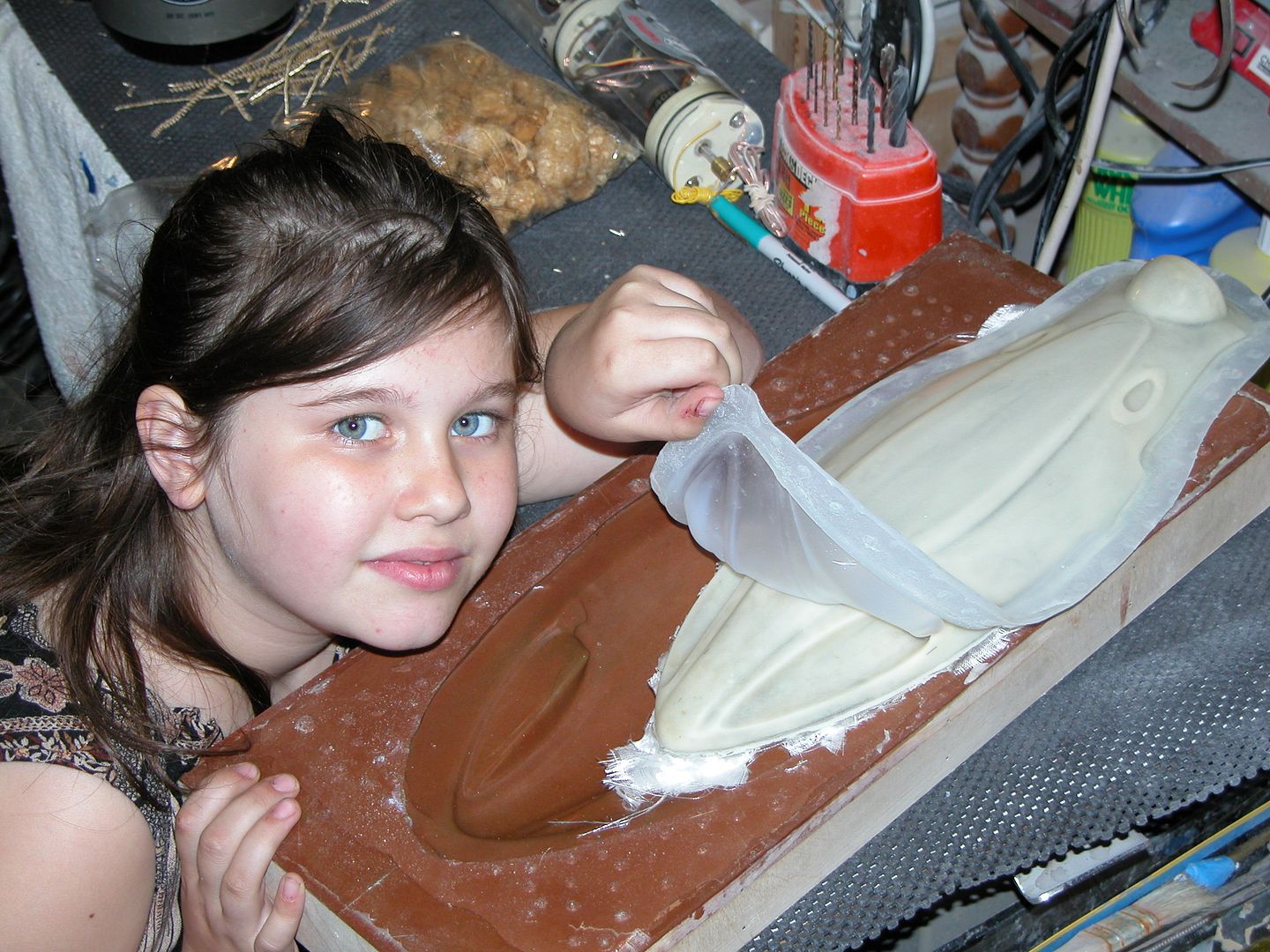
                        After eventually prying the master out of the lower hull I inspected the detail and found that the gel coat did a really good job of getting the detail and that even subtle weld lines and etching that I had put in had translated. All I had to do now was wash off the PVA film from the pull and then apply some more and I could get on with the first hull part layup. The Silicon mould would now get a spray of Stoners release agent and some PVA around the edge of the fibreglass hardback. A could of layers of this and then the first grey gelcoat could be poured into the mould. I usually thicken up the resin so that it almost resembles a paste that will hang to the sides of the moulds mainly the top mould and cling where needed to the undercuts that make up the long missile deck grove that runs along the side of almost all SSBNS.
                        Then once dried a fine weave of 4 oz then some of the chopped strand that I have an endless supply of...

                        These photos show the result of the two hull halves, the rigidity of the silicon mould where the mesh is embedded and also the full set of tooling for this boat. The first two hull halves are also being laid up...

                        More later.
                        Comments, suggestions welcome.


                        Click image for larger version

Name:	IMG_4703.JPG
Views:	81
Size:	9.3 KB
ID:	122302Click image for larger version

Name:	IMG_4704.JPG
Views:	81
Size:	12.3 KB
ID:	122303Click image for larger version

Name:	IMG_4705.JPG
Views:	110
Size:	11.9 KB
ID:	122304Click image for larger version

Name:	IMG_4737.JPG
Views:	77
Size:	9.2 KB
ID:	122305Click image for larger version

Name:	borei complete tooling..jpg
Views:	104
Size:	15.8 KB
ID:	122306Click image for larger version

Name:	borei layup one..jpg
Views:	82
Size:	8.4 KB
ID:	122307

                        Comment

                        • Davidh
                          Captain
                          • Nov 2010
                          • 719

                          Hello All,


                          It's been another busy week and started with the layup of both hull halves. As mentioned they started life as a thick gel coat of grey polyester resin and then once dried a fine layer of weave was laid down. From here a couple of layers of the home made chopped strand was laid down in order to give the hull the strength and rigidity that It would need. Pulling the hull from the top mould will be easily. It will just peel off the silicon mould. Obviously the key will be to getting the missile deck surfaces and sides , straight and the rounded hull, rounded.

                          I make sure that there is plenty of weave around the rim where the glass meets the edge of the hull that will eventually be cut down to a level edge. I will also brush a layer of resin around the outer edge to make sure that the material is neat and consistent till it hits the rim. Any excess resin helps to act as a marker for the rim line that is sanded and cut down to the right length, later..

                          Finally after a couple of days the layers were dry and it was time to pull the first hull out of the moulds. Peeling the top mould out as mentioned was easy and once again the level of detail that is replicated in the silicon moulds is amazing. running my eye down the length of the hull in the morning sun I could see only minimal undulation and certainly none around the missile deck area. there were dimples around the base of where the sail is situated however these would be easy to fill in and sand back. One thing I did notice was that there is absolutely no lumps caused by air bubbles caught in the original silicon mould, Not one.

                          The bottom hull came out of the rigid mould with a little more persuasion and the detail that was embedded in the glass mould also came out quite nicely. These were mainly main ballast tank vents and some hull lines.

                          The top hull is straight and level and although there was evidence of pockets underneath the raised deck forward of the sail these could also be filled in and sanded back. This is caused by not enough resin fill in some areas of undercut in the initial gel coat. I will simply be more vigilant with the next lay up and pack some extra weave into these tight spaces.

                          As can be seen, I am still yet to reach the' holy grail' which is the ability to have the hull part pop out of the mould and have to do virtually nothing to do to it. Each hull will still need some work on it however I have found the need to do less.


                          Till next time....


                          Click image for larger version

Name:	IMG_4736.JPG
Views:	82
Size:	9.3 KB
ID:	122357Click image for larger version

Name:	IMG_4721.JPG
Views:	80
Size:	17.0 KB
ID:	122358

                          Click image for larger version

Name:	IMG_4708.JPG
Views:	82
Size:	11.1 KB
ID:	122353Click image for larger version

Name:	IMG_4711.JPG
Views:	77
Size:	15.4 KB
ID:	122354Click image for larger version

Name:	IMG_4712.JPG
Views:	77
Size:	18.6 KB
ID:	122355Click image for larger version

Name:	IMG_4736.JPG
Views:	76
Size:	9.3 KB
ID:	122356

                          Comment

                          • HardRock
                            Vice Admiral
                            • Mar 2013
                            • 1609

                            Looking great Mate; and, I have finally discovered that there is a practical use for a pool fence!

                            Comment

                            • Davidh
                              Captain
                              • Nov 2010
                              • 719

                              Hello all.


                              Thanks Scott, I have to say that the Romeo is coming along beaut. I can't wait to see it and also the Delta that you have been working on. I have never seen this kit before. Is there a website for it?

                              The two hull halves have had a little touch up done. I have pulled out the sanding board which is just the underside of my marking out board, just with long strips of sandpaper on the underside. I then rub the upper and lower hulls up and down this board until the part line has been reached and also the lines are absolutely level. I also sand just inside the lower edge of the top hull as this has to ride over the outside of the lower hull lip, when I install that one.

                              I also turned my attention to working with the Sail/Fin. This component I had left aside for some time but it was now time to get back to it. I worked out which holes that I wanted to cut out for the masts and also the crew hatch. Drilling and filing these was pretty straight forward and allowed me then to work out the corresponding holes in the top of the side pieces that had been glued together a while back. I wanted the smaller holes underneath the top to be tighter allowing the various masts to, to an extent free stand. I also needed to work out drainage holes for the air to escape whilst diving and air to ingress whilst surfacing. I did not cut out the square for the crew. The top of the sail sides acting as a base.

                              Once this was done it was time to finish off the mast heads. I have some urethane cast parts. Radar masts and Radio masts I think. Sprayed, painted and attached to brass tubes that will get some silver paint to simulate the real thing. If anyone can give the low down on the actual masts on Dolgoruki and what they do, that would be greatly appreciated.

                              Once the holes had been drilled and the masts lined up appropriately I could look at gluing the top onto the sail. Straight forward glue job with some CA and then filler around the sides followed by sanding.

                              I have like all of us spent time looking over weathering and colour schemes. Looking at Dolgoruki and her anechoic tiles I have realised that from almost all angles she looks grey. Also the tiles are subtly noticeable in almost all pics. I decided after looking at Scott's weathering efforts (Antipodean weathering Meister) that I would emulate the tile technique that he has used. After initially toying with the idea of using mesh, that was pretty quickly slapped down by aforementioned weathering Meister as just not practical. Bite the bullet and spend some time laying down tape strips.

                              I bought a cheapie little Ozito spray brush $25 at Bunnings hooked up to my trusty new compressor. ( I love my compressor...). A fast entry in to the world of spraying. Spray a base coat of black on the sail and then apply tape. Next day time to spray with some very dark and matt grey. I cannot believe how good the result looks.

                              I have spent a fair amount of time working out the placement of parts and how they will integrate. I find that when I am assembling the final parts to make the first model, that the tail feathers are the most time consuming part of the whole exercise. Incidentally I was just thinking the other day on how my modelling procedure and philosophy has changed over the last 6-7 years. I no longer make parts to build a final model. I now make parts to make moulds and dies and incidentally a model comes out of those. It's interesting how , doing it this way we don't see the actual finished product until the very end. We are really creating sets of tooling.

                              Back to the tail feathers. I have been carefully sanding and aligning the tail sections so that they all fit together and are aligned. This can be fiddly and subtle lines and angles can throw you. I spent some time making sure that the stern planes were level and that the rotating shafts are exactly paralel with each other and the centreline of the lower hull. then do the same for the vertical rudders.

                              More later.

                              Click image for larger version

Name:	IMG_4805.JPG
Views:	119
Size:	16.7 KB
ID:	122603Click image for larger version

Name:	IMG_4809.JPG
Views:	103
Size:	20.5 KB
ID:	122604Click image for larger version

Name:	IMG_4816.JPG
Views:	83
Size:	15.9 KB
ID:	122605Click image for larger version

Name:	IMG_4815.JPG
Views:	101
Size:	16.8 KB
ID:	122606Click image for larger version

Name:	IMG_4818.JPG
Views:	113
Size:	18.5 KB
ID:	122607Click image for larger version

Name:	IMG_4812.JPG
Views:	98
Size:	19.6 KB
ID:	122608Click image for larger version

Name:	IMG_4821.JPG
Views:	109
Size:	18.5 KB
ID:	122609Click image for larger version

Name:	IMG_4814.JPG
Views:	101
Size:	16.8 KB
ID:	122610


                              Comment

                              • HardRock
                                Vice Admiral
                                • Mar 2013
                                • 1609

                                Looking great Dave. I like the tiles.

                                Comment

                                Working...