

Its looking good Dave.
-
-
In a week where our Prime Ministers name went from Mr Turnbull to Mr Trumble, I have been busy..
Thanks for the prompt with the photo's for the Pump jet detail David, really helpful. I have realised that the stern planes and the Pump jet propulsor arrangement is pretty much at the end of it's development. I therefore decided that I was in a position to start looking at creating the tooling (RTV Silicon moulds). I decided a couple of weeks back that I would continue to colour code the tooling for the various models. Mike silicon moulds are white, Resolution are Orange and for Borei I have gone with a light blue. This simply makes it easier when I look in the big box full of silicon moulds to easily pick through the colour I need. Forward thinking.. I know..
I started off with the limited amount of silicon I had left I thought that I would start with the forward shroud support. This is the 4 support ring that slips over the very end of the hull and the shroud fits around the tips. The propulsor fits inside. This is a relatively simple mould to create. The part has no really complex geometry and shallow draft angles that should'nt cause too many problems and getting air bubbles out shouldn't be too difficult. I simply took a piece of old bench top as I am in the habit of doing and carved a ring in which the inner ring of the support could sit inside that would then allow the unit to be slightly below the plane of the laminate top. This would be the parting plane between top and bottom. I then got out the yellow plasticene and moulded all around the outside. Once completed a couple of shallow drill holes to give a nice series of register points, then glue down an acrylic tube over the top. Mix up some RTV silicon , I use a Dow corning product called "Silastic 3481 base" and mix in some natty light blue pigment. In no time I have a lovely Blue Gatorade thickshake. Pour over the mouild inside the acrylic tube and wait till morning.
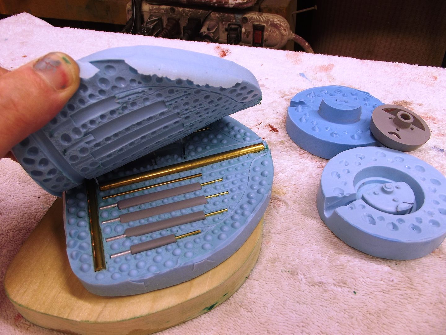
In the morning the mould has hardened and all I need do was break the acrylic tube off the laminate base. It had been held down with a light dribble of superglue. Once the mould has been slid out of the tube the quality of the mould can be checked. The detail that can be picked up in this material is fantastic. Once the master part has been pulled out the inside of the mould then receives a coat of lanolin or vaselin just to give a good release agent. Then the part is inserted back in and a series of air vent and pouring sprues can be located. I glues two small brass pipes either side of the main ring. I then placed two pieces of Yellow plasticine that has been shaped like funnels to sit around the top of the two brass pipes. When the silicon level rises it should sit level with the top of the plasticine forming a funnel to pour urethane into the mould. the air vents are simply pieces of thing styrene strip glued to the top ridge of the four arms, hope fully to guide air out.
Once this is done then rub Vaseline inside the acrylic tube and then slide the bottom moild up into the tube, the seal created by the silicon lower half is excellent. Once done, pour more RTV....
Come back the next morning and slide the whole ensemble out of the tube and pry apart. Two beautiful mould halves, a few styrene air tube to hull out and some brass tube and plasticine to scrape away to reveal two purpose made funnels. You will notice on one side of the mould there are two registration holes, this helps orient the piece and make sure it is seated easily the right way...
Once these parts are clear of the formwork and maybe a few more air holes drilled the mould is then ready for production. At the moment I am still running the gauntlet with non degassed or pressurised urethane castings, I'm still awaiting an order for a mike or a resolution to get the funds for a decent pressure pot..Then when I'm completely set up it should be "hello bubble free"
Enough for now,
appreciate the comments, new ideas etc...
David H
Attached FilesComment
-
-
Very nice description and photos. When I create my molds it is different than the way you did yours, but I learned a new approach. Thank you.If you can cut, drill, saw, hit things and swear a lot, you're well on the way to building a working model sub.Comment
-
Hello all,
This weeks been flat out and as we've come to expect, its 9 pm and its still 30 degrees outside. Today was close to 40 and tomorrow is going to be around 45. I think tomorrow, I will clear out the fridge of food, get inside and close the door and stay there all day...
Flt out at work and little time to work on Dolgoruki however the other big news is that we sold our house and bought a new one. This one comes with a big enough man cave so that you will not have to see any more pic's of my boats on the bins. I will actually have workbenches and room to do stuff ! This place comes with a very long garage with long shelving running down the length. This will allow me to set up a pantheon of submarine development. Wall to wall Subs,,, Nice! Maybe I should christen this new workspace "Severodvinsk south"....
Anyway back to it.
I have managed to do some more silicon moulds. I haven't however poured any urethane castings as with out a pressure pot and the humidity running at about 70% I spend most of my time dripping.. So any urethane moulds I do would be just full of bubbles. But now with my U-beaut garage and man cave I will have the room for a compressor and pot. YAY!!!
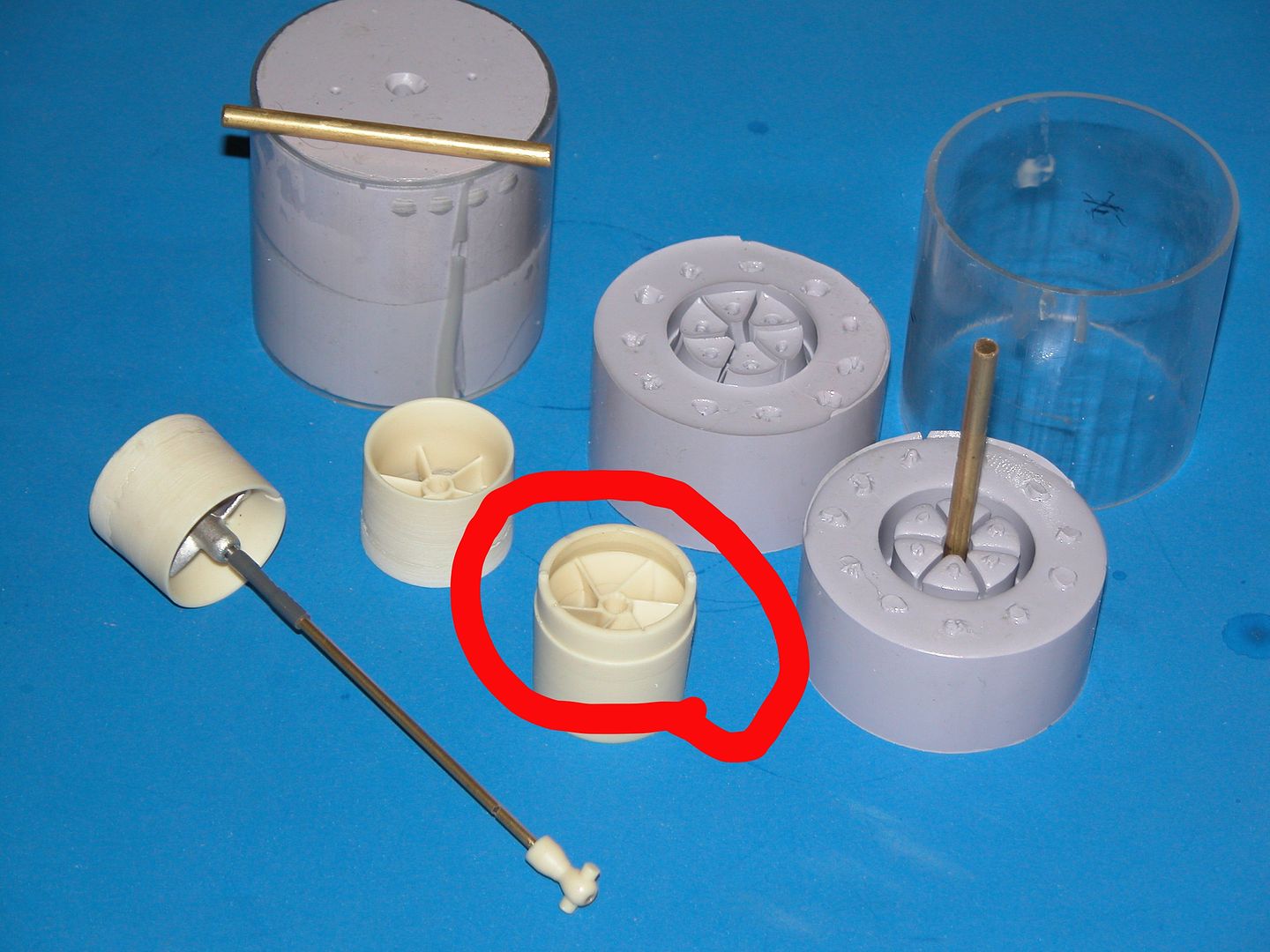
The propeller mould would be one of the most challenging to do. Although HWSNBN doesn't like the design, blades being too oversized and I agree however this prop is going to push some serious water and although the pitch is aggressive its a relatively small diameter. I do have another prop that is a 15 blade design and I would like to create a mould of it one day however I just have to perfect how I'm going to do this one.
Of concern initially was how and where to make the dividing plane between the two halves of the mould. I decided to take a piece of laminated timber, (the usual surface that I use to create my mould surfaces on) and start with the Dremel grinding out a profile that generally conformed to the front surface of the prop. After this, carefully pressing plastincene into and under the frontrims of the blades would allow for a raised separation between the two moulds and would then allow the two parts of the mould to be pulled apart with a slight twist. The mould would be poured through the back of the propeller. This would allow me to insert a 4mm stainless steel threaded rod in between the pouring vents. This screw would simply create the threaded profile in the back of the prop.
Seat the prop inside the cut out profile of the prop in the timber and gradually work around and grind out extra material till the prop goes lower and lower till its a little under halfway in . Drill small shallow holes in between the blades and you have your register points. I will always differentiate one so that you can clearly see on a circular mould how the two parts line up. This was done with a little balsa wedge that was raised above the surface and would produce a register point quite different to the rest.
Once the first mould was poured I then had to think about how to vent the mould. I decided to glue small little plastic strips to the ridge of the blade, they look like little hocket sticks, These would hopefully act as channels to funnel the air up as the mould is poured allowing the air to ride up the surface of the blade and then exit these small holes. Once again the pouring sprue is made of brass pipe with some plasticine pressed into the shape of a funnel. In this case I got cunning and made one that is slightly triangular, very postmodern of me.. the idea being to pour the silicon till it is just sitting level or just under the rim of the plasticine. Once set the plasticine and tube is removed and you have a nice funnel. Then with the inserting of the threaded screw and a spray of release agent, the second part of the mould can be poured with this piece inside the acrylic tube.
I am quite happy with the end result.
David H
Comment
-
Consider pouring low-temperature metal through a single sprue. Either gravity only or centrifugal assisted.

DavidWho is John Galt?Comment
-
Hi all,
thanks David for the suggestion. I haven't used the high temp silicon that can handle the low temp metal castings or I would consider it. I could always re- make the moulds later..
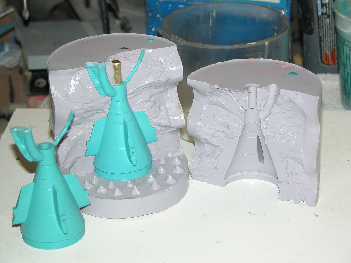
Another busy week and haven't managed to do a lot. I have managed to work my way through the various pumpjet propulsor part moulds. The next one to work on was the main shroud that mounts onto the forward four support mount at the front. This would need a two part mould that is quite deep. I redesigned this shroud to include small little recessed to accommodate the four supports as they attach� to the front rim of the shroud.
The set up is similar to the four arm stator support in that I mounted the master pattern piece on a laminated board and then I take the dremel and cut out a round ring profile to then mount the piece in. this allows the mould to come half way up the shroud. I decided to mount the piece upside down so that the front of the shroud is at the bottom. The top of the moulded part is the rear lip which will actually slide underneath and inside the rear stator extension. This is also so that If I do encounter air bubbles they will appear around the lip in an area hidden underneath the front of the stern shroud section.
Once this mould was poured I would then turn it upside down and repeat the process but this time adding the vent tubes and two sprues either side of each other. The air vents are simply made of styrene and are glued to the very rim of the part. Then the two brass sprues that needed to teeter on the edge and ontop of that would be the rounded plasticine for the funnel, level with the top of the silicon.
David H
Attached FilesComment
-
-
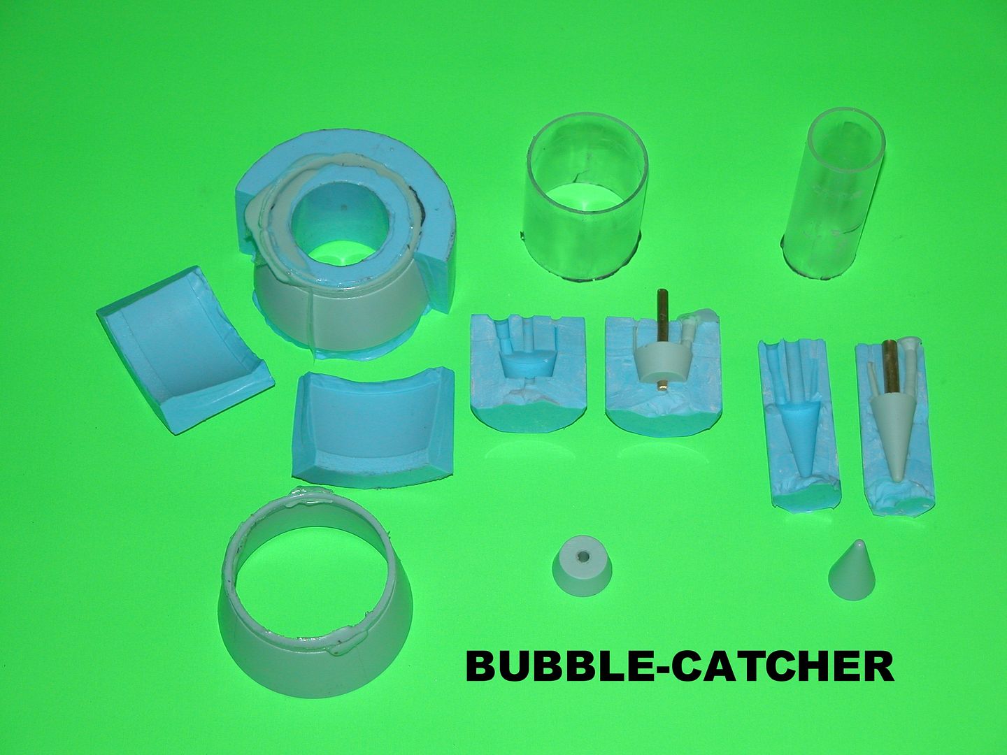
A much better way to relieve the cast shroud-ring of air-bubbles is to replace those little vent risers with a 'bubble-catcher' ring attached to the top end of the duct. The base of the bubble-catcher is chamfered and beveled to a knife-edge before being glued atop the shroud master. The resulting cast part can have the bubble-catcher simply snapped off or parted on the lath. The technique assures a bubble free casting every time.
David
Last edited by He Who Shall Not Be Named; 02-18-2017, 09:11 AM.Who is John Galt?Comment
-
Hi all,
Thanks David for the details about the Bubble ring. It makes sense.For now with the moulds virtually done, extra air vents may be needed but in further moulds the bubble ring will probably be used.
I haven't been on for a couple of weeks as I have been packing up the house ready to move. Boxing up everything is the pits. Sooo much stuff to do and so much crap to throw out. It is amazing the amount of stuff you accumulate over 15 years in the one place. Anyway as you can see from the photo, I'm going to a better place, (workshop wise,that is..)
The photo of the garage with the white wall is what I say farewell to. Most of my work was actually done on top of the bar fridge! That was pretty much the only workspace I had till I pulled out the foldup bench to work on my boats in the last couple of years. (had to back the car out for that one)
The place I'm going to looks like it was hardly used. As you can see, two widows and room for benches and shelving. Maybe another workbench in the middle. Lots of room to hang my gliders in between the roof joists and I'll find a little area to shelve and locate my Amateur Radio set up. I'll have some big shelving put in along the back wall for subs and tooling boxes and a bench in front of the main window so I can watch the kiddies in the pool.
3 weeks to go.
Mould design.
Anyway a couple of weeks ago I did manage to start creating the moulds for the vertical rudders , both top and bottom. I have not completed creating the two halves yet, only going as far as one, and then packing barged its way in. However creating the arrangement for the mould once again meant considering the venting of air and the pouring sprue. I tend not to like long sprues as I think that pouring can be slowed down and vital seconds lost as the urethane thickens.and so like to have the parts reasonably close the top of the mould. This is also the logic behind moulding funnels into the top of the mould as I can pour a fair amount of resin in and let is run into the mould while I then move onto the next one. I like to have reasonable amounts of space between the parts to allow air vents to work their way up to the top. I try and make sure that air vents are not too close to the funnels and all it takes is a dribble of resin to drop onto the top of the tiny air vent and that could potentially back up the air and trap air bubbles.
I make the vents by gluing down paper clips to the face of the mould. I then place these inside the first half mould and repeat the process, then taking these paper clips out and you have a nice small round tunnel for air to escape. As you can see by the mould set up I have put a piece across the bottom of the mould. This is simply an effort to use less silicon.
I don't know If I'm going to be around for a while, It will probably take me a couple of weeks to get the new workshop and man cave sorted....
Scott, the Romeo is going gang busters! I would love to see some shots of the internal arrangement and some more close ups in the water....
David H
Comment
-
Dave, you�ve come a long way since your first post here. I�m impressed with your progress. We�re at the fine-tuning point of your model-building course.
Will you please stop playing it cheap with the consumables! Crummy wood (scavenged, of all things!); cheap laminating resin; poor selection of hand-tools, all examples of the wrong choices you�ve made in this field. Your work has now attained a level where you can make the best use of pattern-making mediums, resins, and hand-tools.
Buy the best! Don�t go cheap on the things you need to produce quality work!
Quality begets quality, my friend. You can spring for a new house � you can spring for the proper shop consumables and tools.
A further amplification of the �bubble catcher� concept is this shot of the tool and two resin castings of our 1/96 Type-212 tail-cone. Two things of note here: the relatively tall sprue distance, in this case a sprue that stands about 1/3 the height of the casting.
The taller the sprue, the greater the pressure-head of the resin at the base of the tool � the quicker the fill. The farther down the tool cavities from the point where resin is introduced, the better. Don�t be shy about investing the rubber needed to create a tall sprue in your tool. Basic physics: the pressure of a column of fluid is dependent on height. Not width!
The �cone� thing isn�t getting it!
Note the sloppy appearance of the main sprue and vent channel captured as positive structures in the raw castings. Those channels were cut into the tool, not formed by mandrels or other do-dads.
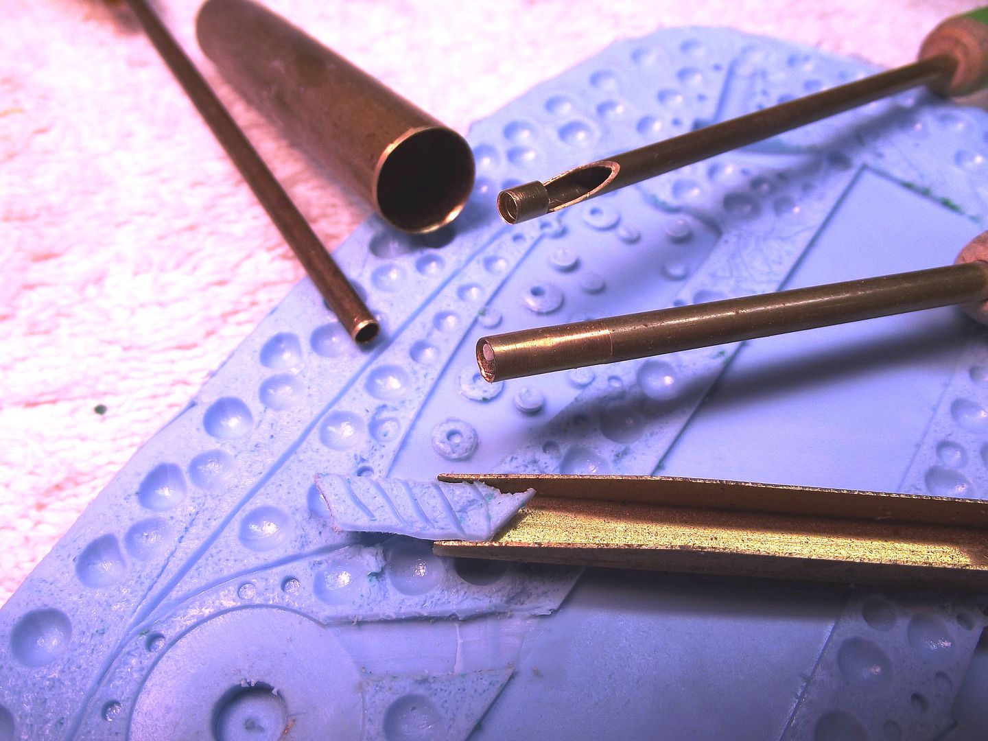
You�ve put so much time and effort into working out those paper clips to form vent channels. Too much fooling around. Instead, make your tools without them and cut the vent channels into the flange faces of the tool halves with specialized gouges. Here you see round and square tubing cut to sharp ends and used to gouge out the vent channeling and runners into a tool.
Note the height of the sprue. This is not a waste of rubber � it�s an investment!
Brase rode was used to represent the sprue and main runner. However, I used a gouge to cut in the vent channeling into the half of the tool that captured the impression of the clay flange face. Note the dimples and dimple cavities that form the physical network of alignment keys that hold the two halves in exacti registration.
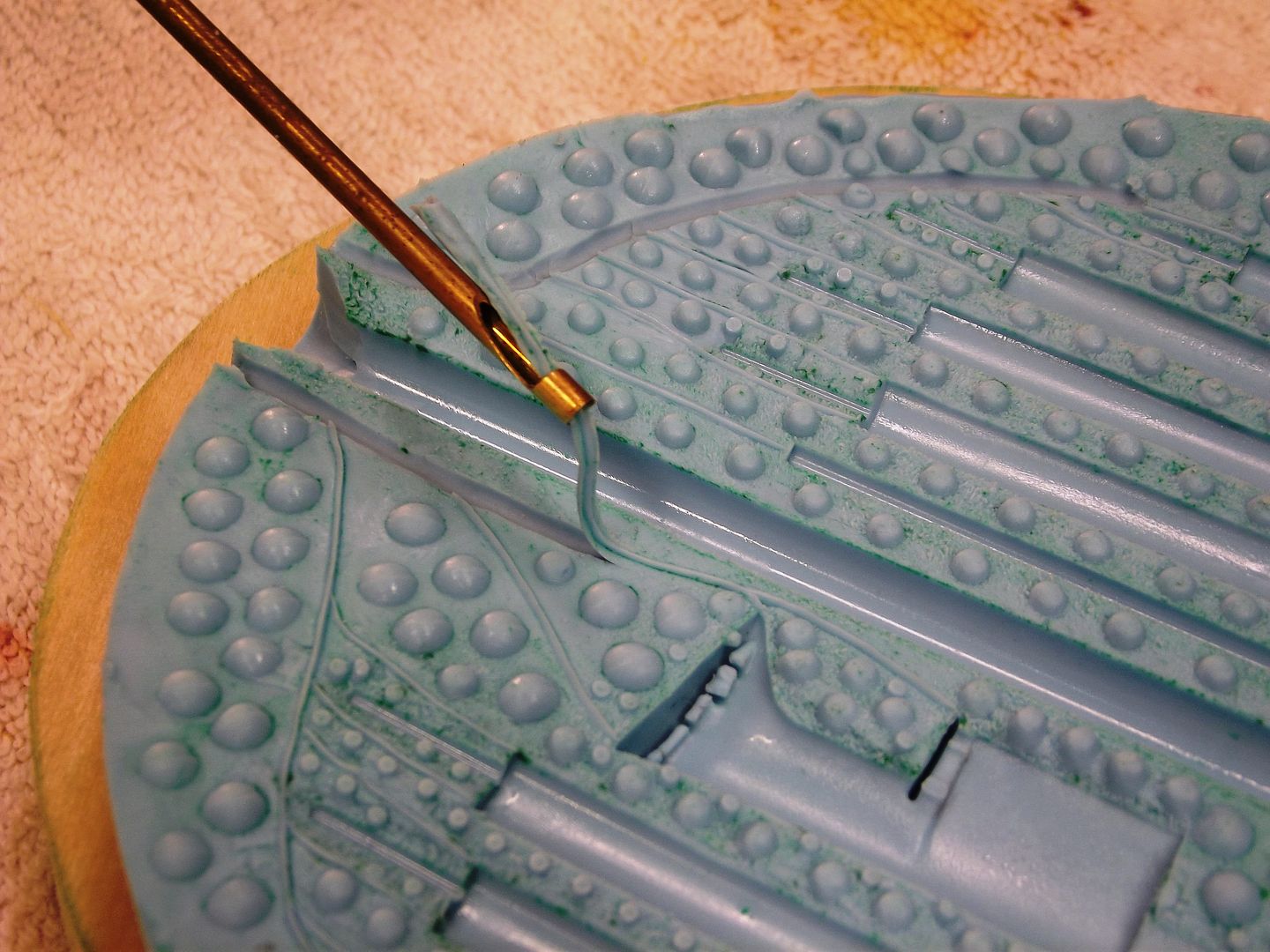
Here you see a round-gouge used to cut the vents into one-half of this 1/96 BLUEBACK mast tool. An easy and quick task. Note the opening near the cutting edge of the tool, this permits a continuouse gouge as I steer the tool over the raised vent channels.
These �positive� channels, seen here on the face ofthe first tool half, initially pressed into the clay face during tool fabrication.
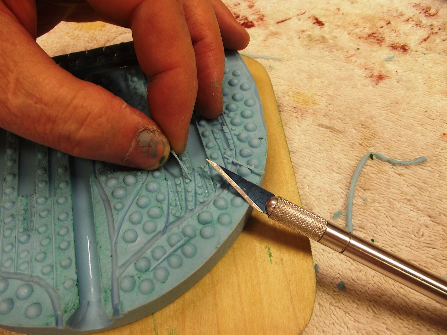
For neatness sake you want the vent opening at the top of each cavity to be as small as possible. The gouge won�t permit that, so you switch to a sharpe X-acto blade to connect the broader vent channeling to the cavity. Dave: note how close the sprue opening is to the main vent channels. No sweat.
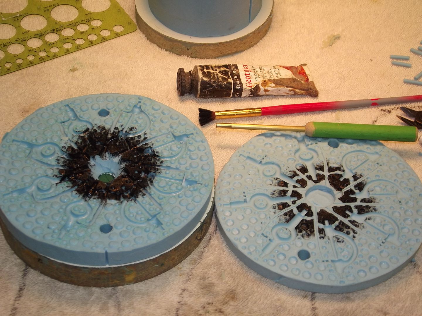
If you�re dealing with a tool that does not have the initial positive of the vent channeling, then you can do this: into one halve gouge out the channeling (yes, I know, this centrifugal tool makes use of sprue and runner channels only � work with me here!); then coat the worked areas with black oil paint; press the second half of the tool in place; and follow the un-black areas with the gouge. This way you have reasonably registered channeling in each half of the tool.
All of this is a lot easier than all that paper-clip and rod nonsense during rubber tool fabrication.
David
Who is John Galt?Comment
-
thanks for that advice David, really helpful.
Its been a couple of months since I posted on the progress of Dolgoruki as mentioned earlier been very busy with moving house. We have finally moved and I now have a serious man-cave. It is perfect for my needs and has a sub friendly swimming pool literally 20 metres form the back of the garage. What more could you want? After dealing with boxes and finding places for things to go, I finally got around to building a decent workbench. I went over to a colleagues house and raided his large supply of recycled timber, finding some gems in there. It's amazing the timber people throw out. Some beautiful Australian Hardwoods, Eucalypts such as Kourri and Jarrah. Spent two days with some borrowed power tools, PVA glue and heaps of screws and hey presto a bench that will out last me.
Once that was in place I could look at unwrapping Dolguruki form the table cloth she had been wrapped in and plot my next move. Placing her down on the bench I realised that I was half way through moulding the stern vertical planes. I had done one half that HWSNBN was not happy with and simply needed to do the other side. So one of the first tasks was to create the box for the second side and then pour the silicon for this one.
I decided before the move that the fin , both sides and top piece had pretty much all the detail they were ever going to need. As David has mentioned you get to a point where you could detail further but it starts to get cluttered and if you can't see the detail from 40 metres away then you shouldn't see it on a model from 400 mm away. So I decided to make the mould box for the top of the sail. I decided however to further mount it on a raised platform and then glue it down inside the mould box. Put the sides up and then pour the blue tinted silicon. This would be a simple one piece mould and would then feature a Fibreglass layup to produce the top of the sail.
I may be able to write another instalment before I leave on long service leave. 17 years in the making and 7 years overdue. In three weeks, Europe here I come!
David H
Comment
-
Don't know you will visit Antwerpen, if you do, we can meet.
grtz,
Bart
Practical wisdom is only to be learned in the school of experience.
"Samuel Smiles"Comment
-
Hi Bart,
Would love to , however the closest I will be is Amsterdam and Copenhagen.
david hComment
-
Hello All,
I have managed to spend a little time this week doing to the odd little bit of work on Dolgoruki before I head away on leave. Most of my time has been pre-occupied with the moulds for the Sail and the top of the sail mould. Being effectively single side moulds have meant that these moulds are pretty easy to make. the main difference in their use is that I do a fibreglass layup for the parts. These are not polyurethane resin parts although you could pour PU resin into these if you really wanted to. Once I pulled the cured silicon from the master you could inspect the quality of the mould surface. This silicon picks up everything. the surface fidelity is near flawless.
After creating the box for the side sail pieces and letting the silicon cure it was then time to layup a fibreglass side sail piece. We are fortunate in that it is still quite warm here at this time of the year and on the weekend it should be a nice 21-22 degrees. Ok for fibre glassing.
So I spray some Stoner polyurethane release agent and then our down a thickened layer of polyester resin with some grey resin and talc to thicken. Let this set and then lay up some fine weave glass cloth. Cutting out fine strips to lay along the underside of the sail side and larger strips to lay along the length of the sail. Give that a couple of hours and then simply pull the rigid set part out of the mould.
Once you pull it from the mould you clean it up and sand it till it registers with the corresponding other pieces.
I then turned my attention to the hull. I have still more scribing detail to complete on the hull before it is ready to start doing the mounting of the hull to the splitter board that separates the two hull halves. This will wait until I get back from Europe as this is something that you don't want to leave for a couple of weeks in limbo. Doing so also runs the risk of having expansion and contraction issues that may arise by leaving the whole built up mould adjusting to 6 weeks worth of temperate and humidity variation. In the meantime a little more scribing on the bottom of the hull has been carried out and some small build up detail work towards the rear of the boat just in front of the stern planes.
Anyway,
Till next time
David H
Comment


Comment