Scratch Build Project 685 Plavnik K-278 Komsomolets NATO: Mike

Collapse
X
 
  • Time
  • Show
Clear All
new posts
  • Davidh
    Captain
    • Nov 2010
    • 719

    #91
    Hi guys,

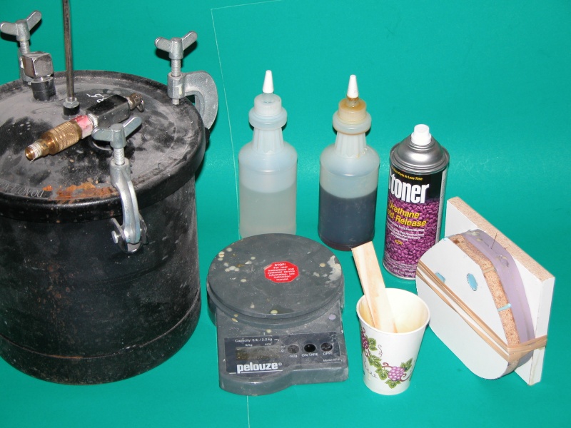
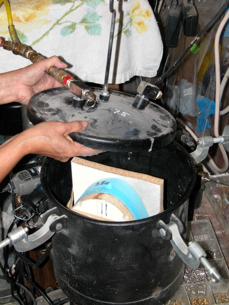
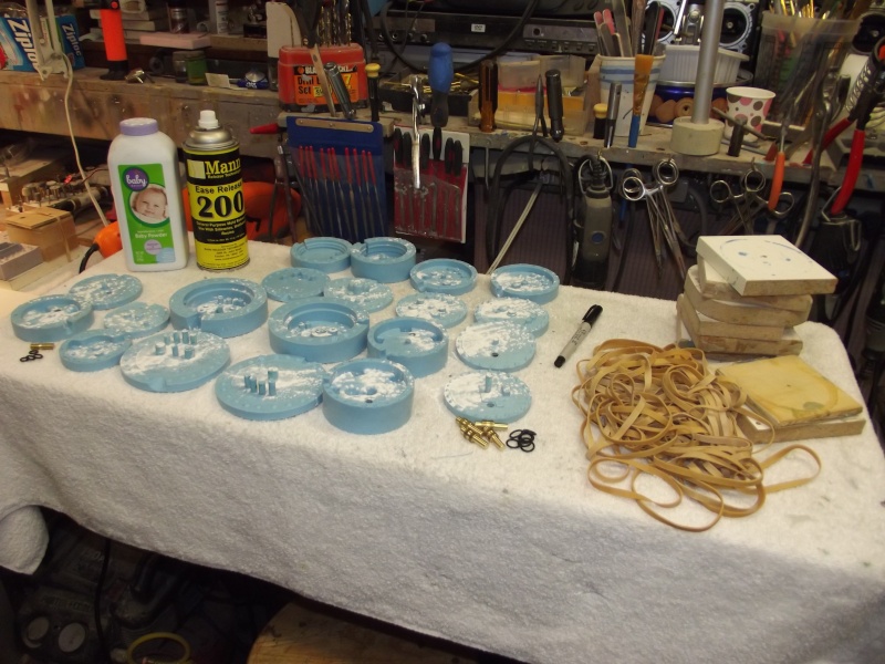
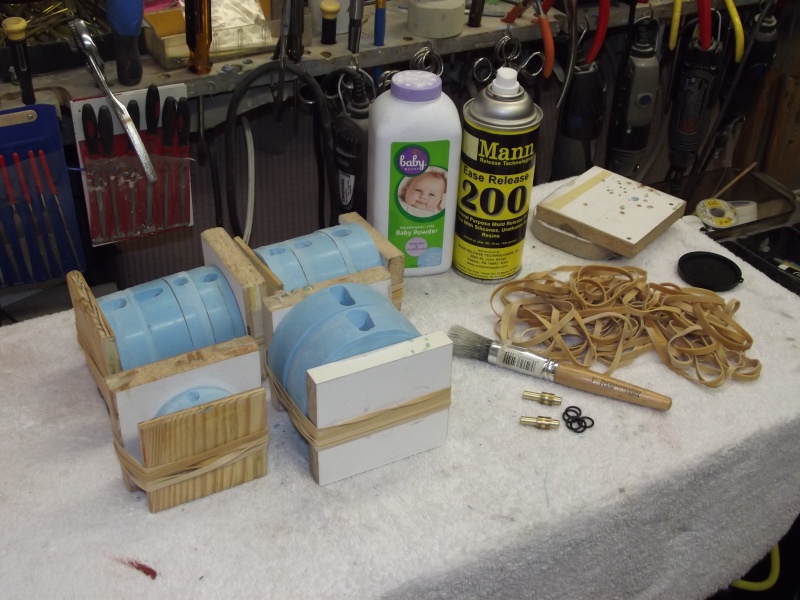
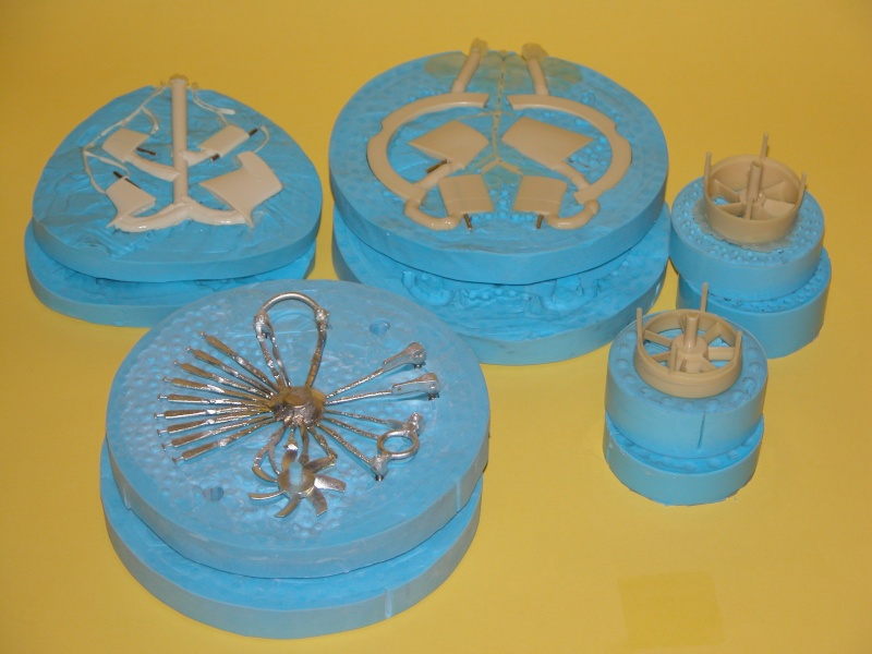
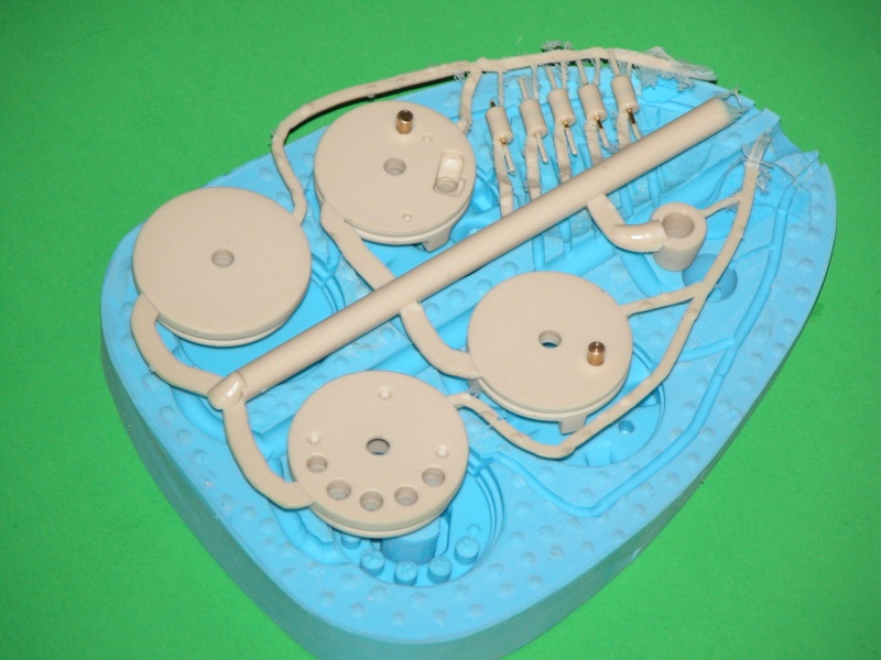
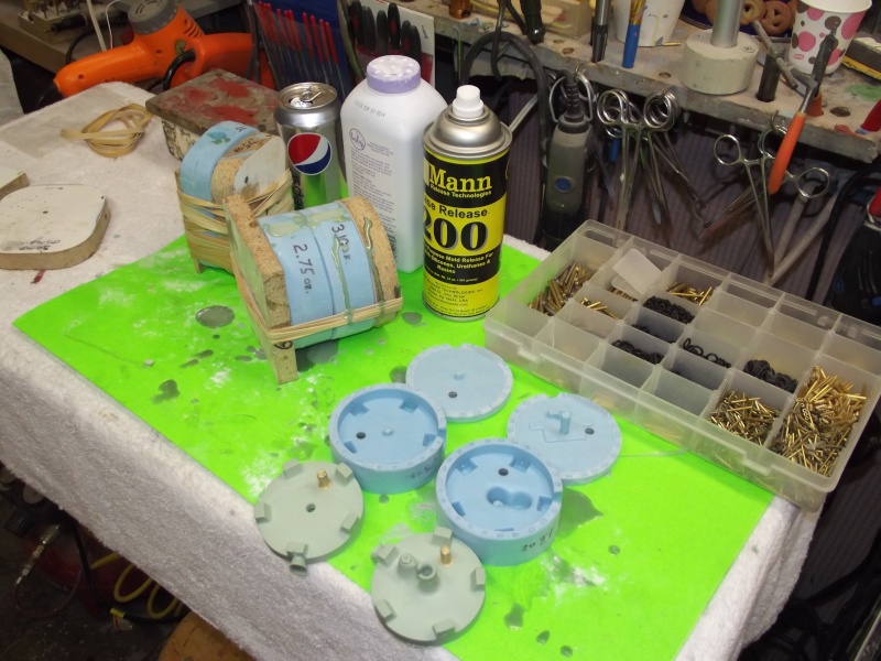
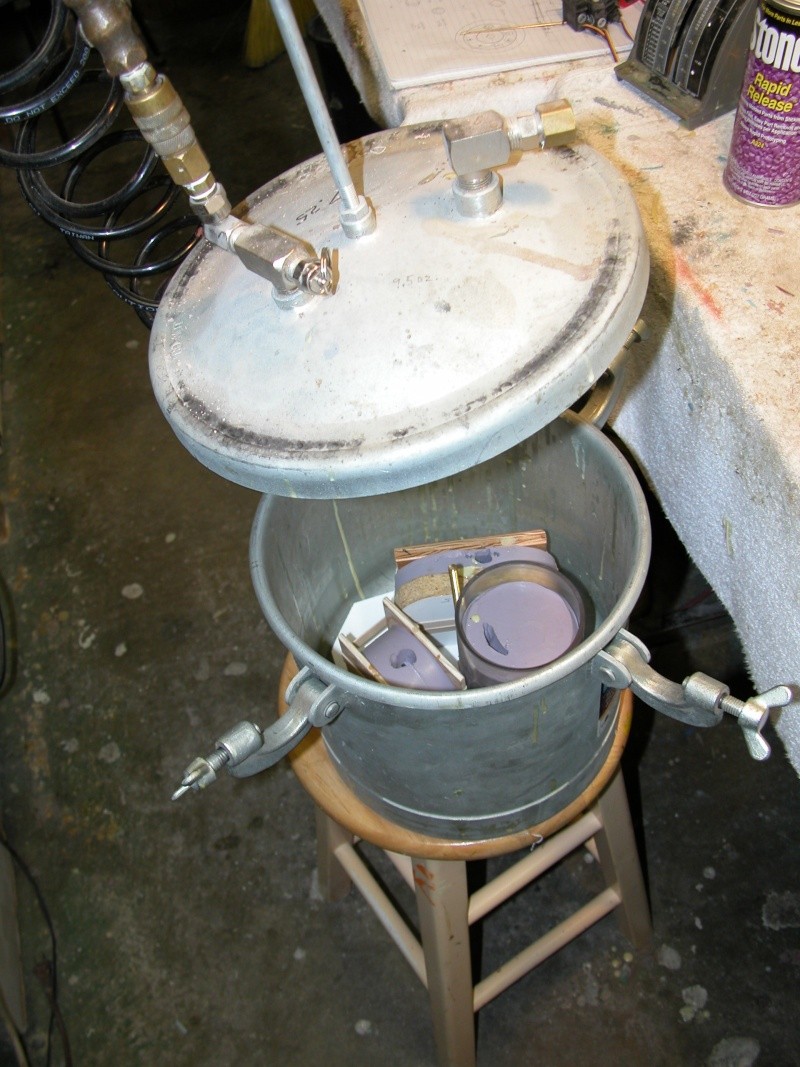
    Thank you for the feedback. Scott I will get some pics of resolutions new sail to you soon. Just laying up some moulds as we speak . Scott T I am not familiar with black silicon, enlighten me. David M thanks for the encouragement. Still trying to work out "business model" for this outfit

    David H

    Comment

    • Scott T
      Commander
      • May 2009
      • 378

      #92
      Just thought since most submarines are some color of black that painting of silicone appendages would not need to be touched up as often if cast in black.
      Click image for larger version

Name:	black silicone.jpg
Views:	182
Size:	48.7 KB
ID:	110940 Click image for larger version

Name:	color silicone.JPG
Views:	154
Size:	21.6 KB
ID:	110941 Scott T

      Comment

      • Davidh
        Captain
        • Nov 2010
        • 719

        #93
        Hello all,

        Thanks Scott T for the silicon information. I am wondering if I could somehow get this silicon into a small mould for these vortex dissipators. I am thinking about getting some of this black silicon and having a play with it. If I don't use it on my subs then I'm sure I will use it on something. Maybe my gliders... I don't know..

        I have started developing the moulds for all the appendages. I have given the fine detail work on the hull a bit of a break and have spent time bringing the Fin up to the stage where I can make the moulds for it and then finally punch out the first finished parts for it.

        Firstly I started looking at creating the moulds for the rear reactor coolant scoops. There are four of them on the Komsomolets and I will make the mould with 4. I have tried really hard to get all them exactly the same and they are pretty good. I can always mould four sets of four and make a kit with all the number two pieces etc... I like to make my moulds in MDF boxes. I like neat and square. I don't mind chiselling out gouges where one surface of the appendage will rest and then creating the pouring sprue at the top and then later on cutting air vents around the side of the mould cavity. I have found that this gives good results. I make sure that I draw the proposed vents in place so that I don't get in the way when I start drilling the register holes. The orange sections at the top are 'funnels' that I have created around the pouring sprue. They make it much easier to pour the resin.

        The next step is creating the recessed deck in the top of the sail. The Sail has a separate top piece and I am going to mould a recessed lower bridge section in the front. This entails cutting out a rectangular section and then creating a box section simply out of balsa. Then a coat of resin and lots of sanding. The tops surface of both sides of the sail will then have an etched outline when the material needs to be cut away to allow the recessed bridge section to drop in.

        As mentioned previously the vortex dissipators are small little suckers... They are so hard to work on because they are small. However I have gone ahead and etched where they will be located on the hull. Black silicon or not...
        Click image for larger version

Name:	_DSC4477.JPG
Views:	81
Size:	46.0 KB
ID:	111048 Click image for larger version

Name:	_DSC4481.JPG
Views:	70
Size:	48.2 KB
ID:	111049 Click image for larger version

Name:	_DSC4484.JPG
Views:	99
Size:	50.4 KB
ID:	111050 Click image for larger version

Name:	_DSC4485.JPG
Views:	75
Size:	46.7 KB
ID:	111051 Click image for larger version

Name:	_DSC4486.JPG
Views:	68
Size:	44.3 KB
ID:	111052 Click image for larger version

Name:	_DSC4488.JPG
Views:	75
Size:	47.0 KB
ID:	111053 Click image for larger version

Name:	_DSC4489.JPG
Views:	74
Size:	44.1 KB
ID:	111054 Click image for larger version

Name:	_DSC4495.JPG
Views:	99
Size:	45.8 KB
ID:	111055 Click image for larger version

Name:	_DSC4498.JPG
Views:	107
Size:	49.5 KB
ID:	111056 Because I am developing this boat as a kit I am thinking about how to make the assembly as straight forward as possible and giving surface detail location points is part of the plan..

        David h

        Comment

        • Davidh
          Captain
          • Nov 2010
          • 719

          #94
          Hello all,

          I have been busy creating the first final parts to come out of the moulds. I have been busy with the RTV , polyester resin and the vinylester resing. As can be seen by the previous photo's I have been creating the two side moulds for the sail. These used up a bit of resin and pouring RTV moulds has been on hold as my supplier had run out of the 1 litre tins. Bummer. Get moulds ready and wait.

          However I have now made about 2-3 sets of sail components. I made a set out of vinylester resin and found that that stuff seems to take so much longer to set than the polyester resin. I also found that I just doesn't quite give the detail of the polyester resin. I laid up a couple of parts out of poly and the result was fantastic. Right down to the side rails and panel lines. Nice.

          The next big job would be tooling up for the moulds/dies of the rear horizontal fins. As can be seen I like to create a wooden box for my moulds. I am fairly orderly with this and so will spend the time chiselling away at a surface to get it right to fit the part around the equator. The filleted sections around the root would require deeper cuts and a steep angle to allow the part to sit level and slightly recessed with the profile outline. Once this is done then cutting the sprue channels and putting a small piece of brass rod in place to act as the sprue is required. This is followed by filling around all the edges with plasticine and then creating a funnel around the tops of the sprue. I find this makes pouring the moulds/dies way easier. Then drilling registration holes and making sure that they do not get in the way of proposed air vent lines. Then box it up and pour.

          The two mould halves for the horizontal planes have turned out really well. After this, casting of the final pieces could occur. This is the first die/mould that I have created that features removable brass shafts. Brave new world. I gave these a coating or Vaseline and then inserted the required brass rods in place. Strapped up the two halves in between plywood supports and poured in the resin. 3 hours and 28 degrees later the castings were hard and they came out well. The air vents did their job as their were only the tiniest air bubbles. Gently rotate the brass rod and they slide out.
          Click image for larger version

Name:	_DSC4496.JPG
Views:	84
Size:	45.6 KB
ID:	111158 Click image for larger version

Name:	_DSC4491.JPG
Views:	70
Size:	49.2 KB
ID:	111159 Click image for larger version

Name:	_DSC4492.JPG
Views:	71
Size:	48.0 KB
ID:	111160 Click image for larger version

Name:	_DSC4497.JPG
Views:	122
Size:	51.7 KB
ID:	111161 Click image for larger version

Name:	_DSC4499.JPG
Views:	77
Size:	47.6 KB
ID:	111162 Click image for larger version

Name:	_DSC4503.JPG
Views:	64
Size:	50.1 KB
ID:	111163 Click image for larger version

Name:	_DSC4502.JPG
Views:	73
Size:	47.9 KB
ID:	111164 Click image for larger version

Name:	_DSC4504.JPG
Views:	78
Size:	48.2 KB
ID:	111165 Click image for larger version

Name:	_DSC4505.JPG
Views:	89
Size:	45.0 KB
ID:	111166

          David H

          Comment

          • He Who Shall Not Be Named
            Moderator
            • Aug 2008
            • 12321

            #95
            Very good work -- you're advancing with each new project, Dave.

            M
            Who is John Galt?

            Comment

            • Davidh
              Captain
              • Nov 2010
              • 719

              #96
              Thankyou David, appreciated,...


              As mentioned last week I have completed a couple of the sail/ fin components for both sides and have also completed the mould for the top of the fin. That was probably the easiest mould to make. Laying up a gel coat for it then laying up some weave ended up with a nice result that I am happy with. Producing the lowered bridge section in the top of the fin means that you have to cut out the rectangular profile in either side of the top of the fin sides. This makes a nice recess for the bridge section to drop into. The outline has been marked into the moulded side pieces so finding and cutting it should not be a problem for the model builder.

              I am planning on holding off completing the sail and gluing it all up as I want to produce some nicely turned up masts and scopes. I should be getting my mini-lathe in about 3 weeks time and can't wait. A nice little Seig SC2LF should do the job. Turn up some scopes for that then make some mould/dies off those and add them to the kit. So no completed fin /Sail for now. Happy with how the parts have turned out.

              Moulding up more rear planes and creating the moulds for the vertical rudders and moving surfaces has been the other big pre-occupation of late. I managed to get some more 3481 base RTV and off I went.

              I have produced a few sets of the rear planes, these are minus the actual moving planes. these will be the final set of moulds I produce and will be along side the reactor outlet doors at the very rear underside of the sub. I am of two minds as to whether I decide to mould the teeny weeny little vortex fins that are mounted along the upper rear surface of the hull.

              I have come up against a few teething problems on the production line with resin cast parts. Polyester resin is brittle. Drop it and go
              Click image for larger version

Name:	_DSC4507.JPG
Views:	74
Size:	48.0 KB
ID:	111208 Click image for larger version

Name:	_DSC4510.JPG
Views:	78
Size:	46.0 KB
ID:	111209 Click image for larger version

Name:	_DSC4519.JPG
Views:	76
Size:	48.9 KB
ID:	111210 Click image for larger version

Name:	_DSC4523.JPG
Views:	65
Size:	49.0 KB
ID:	111211 Click image for larger version

Name:	_DSC4526.JPG
Views:	74
Size:	48.7 KB
ID:	111212 Click image for larger version

Name:	_DSC4516.JPG
Views:	70
Size:	49.9 KB
ID:	111213 Click image for larger version

Name:	_DSC4514.JPG
Views:	69
Size:	47.4 KB
ID:	111214 Click image for larger version

Name:	_DSC4518.JPG
Views:	69
Size:	46.7 KB
ID:	111215 Click image for larger version

Name:	_DSC4517.JPG
Views:	94
Size:	48.3 KB
ID:	111216

              mould another one. So although I would like to have a look at using something like a polyurethane resin which I believe should do the job. (David what pearls of wisdom have you got?) I have been experimenting with an adjustment of sorts. I have been laying up strips of Carbon fibre strand into the cast pieces. This is to inhibit or reduce the possibility of shattering. I take the mould and wet the inner surface of one side and then lay up some really tiny pieces of carbon fire and fan it out somewhat. I also try and lay it up underneath where there will be a pivot. This should give some strength to the areas around where there will be a rotating shaft as these and usually of the thinnest resin. I then Vaseline up the brass rod and insert it to the place in the mould to create the hole. Then lay the other silicon half on top and the rubber band it and pour. I dropped a cast piece on concrete the other day and it didn't shatter..

              Any advice on the use of polyurethane resins of the like would be good. Unfortunately the nearest supplier is in western Sydney about 2 hours drive and so going and seeing it before buying is unlikely. I will have to order it through Barnes

              http://www.barnes.com.au/


              Any advice on which resin to use would be great.

              Cheers,


              Attached Files

              Comment

              • He Who Shall Not Be Named
                Moderator
                • Aug 2008
                • 12321

                #97
                I have found that encapsulating glass or carbon fiber within cast resin parts to be of little utility. However, selection of the proper chemistry as to the resin you use is vital. Polyester is the worst (high shrink, and difficult to control the cure rate); epoxy is second best but takes a long time to cure and is expensive; and polyurethane is the best.

                From your source you want their Procast Polyurethane resin and Stoner E236 urethane release.

                Here are some shots that will help you with tool design, preparation, and use of pressure to achieve bubble-free castings:


                M

                Who is John Galt?

                Comment

                • trout
                  Admiral
                  • Jul 2011
                  • 3547

                  #98
                  I know a gentle man who used carbon fiber in his hull. He had been run over by a careless surface craft. It really messed up his sub. Well that ticked him off. So, he made a sub the was ready for battle. Unfortunately, after assembling the hulls together, no radio signals would make it into the hull. I guess it is a good shield against radio waves. If I heard correctly, to correct the problem, he made the top section over again with fiberglass, but made a thick rib in there. Not really pertinent to this thread, but wanted to share.

                  Your sail came out really nice. I am absorbing all this information.
                  If you can cut, drill, saw, hit things and swear a lot, you're well on the way to building a working model sub.

                  Comment

                  • Davidh
                    Captain
                    • Nov 2010
                    • 719

                    #99
                    Hello David,

                    Thanks for the quick reply. I have ordered the pro cast polyurethane resin. But am wondering about the stoner release agent. I was under the impression that silicon only sticks to silicon. I haven't been using release agent on polyester and did'nt think it would be needed with polyurethane. Does poly u stick?

                    Also could you clarify the pressure chamber set up you have there, I am not too familiar with it. Or point me to a write you have done somewhere else on it.

                    Thanks,
                    David h

                    Comment

                    • He Who Shall Not Be Named
                      Moderator
                      • Aug 2008
                      • 12321

                      Originally posted by Davidh
                      Hello David,

                      Thanks for the quick reply. I have ordered the pro cast polyurethane resin. But am wondering about the stoner release agent. I was under the impression that silicon only sticks to silicon. I haven't been using release agent on polyester and did'nt think it would be needed with polyurethane. Does poly u stick?

                      Also could you clarify the pressure chamber set up you have there, I am not too familiar with it. Or point me to a write you have done somewhere else on it.

                      Thanks,
                      David h


                      Each time the polyester, epoxy or polyurethane liquid comes in contact with the silicon rubber of your tool a chemical reaction takes place, working to change the properties of the cured rubber. A tools utility is expressed in the number of castings (called a pour, or shot) it can form before it becomes unusable -- such 'wear' observed as wrinkles and tears within the cavities and flange faces of the tool. Without a part-release (the proper term for the stuff -- 'mold-release' is what you use to keep RTV rubber from sticking to RTV rubber during the tool-making process) your tool will only produce a fraction of the number of parts under what is achieved when the tool receives a part-release system before each pour. Also note that that the part-release spray is only one of the two components that comprise the part-release system used to protect the rubber tool from the casting resins chemistry. After applying the part-release spray, you dump talc into the open cavities, close the tool, shake and thump the tool to coat the talc on all surfaces -- a thin layer of talc remaining after you open up and dump the excess talc on the floor. The talc acts as a barrier between resin and tool. It also pulls water into itself (hydroscopic) and off the surface of the tool; and the small mineral particles act to wick the resin (through capillary action) into the tight corners and details of the cavities surface.


                      You can pour at room temperature at ambient air pressure -- providing the resin is fresh. But over time (weeks), once you open up the resin part-A and part-B starts to go sour and will generate little gas bubbles when mixed. Pressurizing the mix after making the pour crushes these little bubbles -- which manifest as pits in the surface the cast resin piece -- back into solution and keeps them there till the resin makes the state change from liquid to solid. Two atmospheres will do it. I use an easy to source and use paint pressure pot. Or you can manufacture your own pressure vessel (make sure to hydrostaticaly test it to 150% of your working pressure first!).


                      M
                      Last edited by He Who Shall Not Be Named; 11-14-2015, 08:40 AM.
                      Who is John Galt?

                      Comment

                      • Davidh
                        Captain
                        • Nov 2010
                        • 719

                        Thanks David for the info..

                        I have bought some Polyurethane resin. I just have to use it now. I will need to get some of that stoned., ops I meant Stoner release agent. I then need to get hold of a Vacuum chamber. That might be a little while. Stumping up the cash for that one. Any ideas?

                        I have now completed the all the silicon moulds for all the appendages for the Mike. All I need to do the tooling for is the two large hull halves. I am going to create the top of the hull with a silicon mould with a fibreglass hard shell. This is going into the unknown for me as I have not done a Silicon mould so large and have not thickened it to a paste to apply, before. So it will be interesting to see how it goes. I have some 'Thixotropic-M' thickening agent.

                        The lower hull will be a conventional fibreglass layup and reinforce. The reason for this is because the detail on the lower hull is much less and not going to be prone to breaking off and the like. The top half is going to take a fair amount of Silicon so I am anxious to get it right.

                        Anyway, the latest round of photos show the appendage parts cast and out of the moulds. Particularly the rear parts. I have yet to create parts for the moving horizontal surfaces and then should be moulded up this week. They are apart of the last mould. However as you can see the rear planes are starting to come out of the moulds and look ok. I intend to pursue the polyurethane resin avenue , however for the moment polyester resin and a reinforcing strip of carbon fibre seems to be working. I dropped one earlier and it didn't break. It does need a little more polishing however, these parts are coming along.

                        I have spent some time over the last couple of months working on an instruction manual of sorts. Pics here of the front page and a random inside with some line drawings. Documentation can take a large amount of time and you have to decide where to draw the line. Huh, Pun get it...
                        Click image for larger version

Name:	_DSC4530.JPG
Views:	103
Size:	47.1 KB
ID:	111344 Click image for larger version

Name:	_DSC4532.JPG
Views:	105
Size:	64.6 KB
ID:	111345 Click image for larger version

Name:	_DSC4533.JPG
Views:	104
Size:	51.1 KB
ID:	111346 Click image for larger version

Name:	_DSC4534.JPG
Views:	74
Size:	49.0 KB
ID:	111347 Click image for larger version

Name:	_DSC4536.JPG
Views:	88
Size:	48.8 KB
ID:	111348 Click image for larger version

Name:	_DSC4543.JPG
Views:	69
Size:	50.1 KB
ID:	111349 Click image for larger version

Name:	_DSC4569.JPG
Views:	69
Size:	48.5 KB
ID:	111350 Click image for larger version

Name:	_DSC4570.JPG
Views:	68
Size:	46.2 KB
ID:	111351 To what level of detail do you got to? To minimise the amount of detail I have put in to the instruction booklet I have made it clear that this model is for someone who has some idea. I could go to the 'N' th degree and detail every conceivable little procedure that needs to be done to get a boat in the water, however I don't think I want to write a 30 page booklet. It's currently at page eight.

                        Any advice?

                        David h

                        Comment

                        • Davidh
                          Captain
                          • Nov 2010
                          • 719

                          Why is my title page upside down. Dang it!

                          Comment

                          • Davidh
                            Captain
                            • Nov 2010
                            • 719

                            Hello all,
                            Click image for larger version

Name:	_DSC4547.JPG
Views:	71
Size:	47.6 KB
ID:	111482 Click image for larger version

Name:	_DSC4549.JPG
Views:	69
Size:	46.9 KB
ID:	111483 Click image for larger version

Name:	_DSC4550.JPG
Views:	73
Size:	56.4 KB
ID:	111484 Click image for larger version

Name:	_DSC4573.JPG
Views:	65
Size:	44.6 KB
ID:	111485 Click image for larger version

Name:	_DSC4574.JPG
Views:	72
Size:	48.0 KB
ID:	111486 Click image for larger version

Name:	_DSC4582.JPG
Views:	103
Size:	48.5 KB
ID:	111488 Click image for larger version

Name:	_DSC4584.JPG
Views:	64
Size:	47.7 KB
ID:	111489 Click image for larger version

Name:	_DSC4556.JPG
Views:	76
Size:	52.5 KB
ID:	111490 Click image for larger version

Name:	_DSC4575.JPG
Views:	80
Size:	49.1 KB
ID:	111487
                            As mentioned earlier all the moulds have been made for the appendages. I then got to make the last of the parts out of resin including the rear reactor coolant outlets, probably the most mysterious part of the boat. Anyway the photo shows the masters and where they align on the rear of the hull.

                            I have also added a raised profile where the sail will be. This will help with positioning the sail when the design is a kit and also will make sure that light will not be seen when you look dead level with the base of the sail if you have not done a neat job of cutting it. Just got to sand it back and get it really smooth soon.

                            I have received the ordered Polyurethane resin that Dave recommended from Barnes. I got the appendage moulds ready and prepared for giving this new resin a try. I was spooked by the whole degassing thing as I do not have a vacuum chamber or pressure chamber to apply to the resin once mixed. I really wasn’t sure if when I mixed the resin and poured it into the mould whether it would end up coming out looking like Swiss cheese.

                            Initially I did not prepare enough moulds for the amount of resin I mixed up and had more than I could use so hurriedly scambled to insert brass inserts into more moulds and tried to pour the remaining resin into those. Nuh, wasn’t going to happen, the resin was starting to thicken and was already as thick as thick honey, man this stuff sets fast!
                            It was interesting watching the colour change of resin, starting off the colour of beer and then going more yellow, eventually to be a nice banana yellow.

                            After a couple of hours I de-moulded the pieces and did not find Swiss cheese. There was maybe one small bubble and I am presuming lots of tiny pin prick bubbles. I had to look hard to find them. However I am stoked at the result. I have since done a couple more pourings, getting the quantities right and less waste and am finding that there are even fewer small bubbles. These parts look really excellent, maybe that’s just my opinion and maybe David is shaking his head and screaming for me to get a vacuum chamber however I can’t see what the problem is with the bubbles I really have to look really hard to see them. Those vortex pods on the ends of the horizontal planes remind me of Bananas being yellow and all, I might just eat one.

                            Once the parts came out of the mould then it was simply a case of trimming off the flashing and then a light sanding back. Pulling out the brass inserts has been easy I did coat them with Vaseline to make it easier not knowing originally if there was a need for release agent. Can anyone enlighten me on this? Any advice on this would be good, it’s been quiet lately….
                            If a part had an insert that fitted into another part like a two piece rudder system then this was easily accomplished as the two parts would fit around the brass pivot really nicely.

                            I am about to order some of that Stoner E326 release. I have also cut up a MDF particle board to make my mould splitting board for the two hull halves. I will screw down a long straight piece of MDF to make sure that the board is absolutely straight then make the rest of the box underneath. Then cut out the profile of the hull at the equator and mount it to the board. I have also cut out some little holders underneath that will hold the underside of the hull just where I need it.
                            I am also in the process of making up a small bench to mount the lathe when I finally get it. Some old tubular steel and a borrowed MIG welder. Then I will be able to make propeller hubs and masts and scopes at home. nice!..
                            Enough for now..

                            Any comments /advice would be appreciated…

                            David H

                            Attached Files

                            Comment

                            • Davidh
                              Captain
                              • Nov 2010
                              • 719

                              Quiet forum,

                              I haven't had any response to the questions I put up about polyurethane and the need for a release agent on metal parts in a polyurethane mould. Surely someone has an answer?

                              Anyway back to the build. I have spent a fair bit of time welding up a tube steel frame to make the bench for the lathe that I anticipate getting soon. The top bench plus two lower shelves should store most of my stuff. Will still be a little bit of a squeeze though.

                              I am about to start the home stretch of this project. I will soon be looking at the moulds for the hull, top and bottom.

                              Last Sunday afternoon I managed to start construction of the moulding/Splitter board that I will produce the hull mould on. Like with the Resolution, I decided to make the customary box around the outside the ensure that the MDF board is absolutely straight and flat. Then I marked out the profile of the hull on the main board and then got the jigsaw ready to cut it out.

                              Cutting out the profile of the hull wasn't difficult and MDF is certainly soft stuff. I cut slightly inside of the profile so that I could file down later and make the fit as tight as possible. Once the boat is at the equator in the board I will go around it with plasticine and get it nice and flush. With all my projects be they Submarines or Sailplanes I try and do something new in the building process for the sake of trying something new and expanding the possibilities. Here I will be making the top mould out of a large silicon RTV mould with a fibreglass hard back. This will require thickening of the Silicon and for this I have something called thixotropic-M that will mix into the silicon and allow it to thicken to a paste that will hopefully mean that It will stick to vertical surfaces around the side of the hull. The lower hull has less detail and not railings moulded into the deck. I will probably just do a hard shell Fibreglass mould for this one.

                              The hull will be supported underneath by two wooden 'handles' that will be screwed up under the underside of the hull making sure that it does not slip down below the equator of the hull.

                              Although mike fits nicely into the board and I could proceed pretty quickly with moulding the two hull halves I will probably spend most of the weekend just getting the hull just right. There are still many imperfections that I should iron out. I also have to finish etching the ballast tank vents on the bottom of the hull. I need to really devote some time to these so it will be a little while before I finally set up the hull for the mould. It's worthwhile getting
                              Click image for larger version

Name:	_DSC4589.JPG
Views:	71
Size:	55.5 KB
ID:	111559 Click image for larger version

Name:	_DSC4591.JPG
Views:	63
Size:	50.6 KB
ID:	111560 Click image for larger version

Name:	_DSC4592.JPG
Views:	64
Size:	50.4 KB
ID:	111561 Click image for larger version

Name:	_DSC4593.JPG
Views:	67
Size:	49.4 KB
ID:	111562 Click image for larger version

Name:	_DSC4595.JPG
Views:	65
Size:	52.1 KB
ID:	111563 Click image for larger version

Name:	_DSC4596.JPG
Views:	68
Size:	47.0 KB
ID:	111564 Click image for larger version

Name:	_DSC4599.JPG
Views:	65
Size:	50.0 KB
ID:	111565 Click image for larger version

Name:	_DSC4602.JPG
Views:	66
Size:	44.5 KB
ID:	111566 Click image for larger version

Name:	_DSC4608.JPG
Views:	92
Size:	51.8 KB
ID:	111567 Click image for larger version

Name:	_DSC4601.JPG
Views:	65
Size:	46.7 KB
ID:	111568 the hull just right, that RTV silicon is expensive.

                              Anyway, enough for now

                              David H


                              Attached Files

                              Comment

                              • He Who Shall Not Be Named
                                Moderator
                                • Aug 2008
                                • 12321

                                When applying the rubber (glove) element of the hybrid tool:

                                1. experiment on something small first -- you don't want to commit all that expensive rubber on the hull only to find later that some step(s) in the process were wrong and rendered a useless item
                                2. vacuum the mix of rubber before trolling it over the hull -- this will eliminate the possibilities of catching air pockets as you troll the rubber down onto the hull
                                3. apply the rubber with a credit card or stiff piece of plastic sheet.
                                4. apply multiple coats of rubber, the nominal thickness of the glove should be between 3/8" and 1/2".
                                5. make the surface of the last coat of rubber as rough as possible -- this will index the hard-shell (mother-mold) GRP to the rubber so they key together perfectly.

                                M
                                Who is John Galt?

                                Comment

                                Working...