Scratch Build Project 685 Plavnik K-278 Komsomolets NATO: Mike

Collapse
X
 
  • Time
  • Show
Clear All
new posts
  • Davidh
    Captain
    • Nov 2010
    • 719

    #46
    Hello all,


    Thanks for all the suggestions from people about the dilemma of the forward bulges / Blisters over the hydroplane housing. All I need is some good photo's of the bow area to clear this up but so far neither Rubin or The St Petersburg Submariners club have bothered to reply which is a bit annoying.

    I really think that I will reduce the size and profile of the blisters and maybe just raise the deck between the blisters by a tiny amount. This is influenced by Barts black cut out profile of the forward deck. Most cunning...

    The photo's continue, one
    Click image for larger version

Name:	is this my better side..jpg
Views:	66
Size:	50.8 KB
ID:	109308 Click image for larger version

Name:	marking out equator on board..jpg
Views:	60
Size:	51.1 KB
ID:	109309 Click image for larger version

Name:	more sanding and fine work.jpg
Views:	70
Size:	48.1 KB
ID:	109310 Click image for larger version

Name:	pesky blister profile..jpg
Views:	68
Size:	44.8 KB
ID:	109311 Click image for larger version

Name:	blister profile.jpg
Views:	60
Size:	47.6 KB
ID:	109312 Click image for larger version

Name:	raise the deck or lower the blister.jpg
Views:	72
Size:	48.8 KB
ID:	109313 Click image for larger version

Name:	marking out and recutting new blisters..jpg
Views:	65
Size:	46.1 KB
ID:	109314 Click image for larger version

Name:	using a knife to reshape blisters.jpg
Views:	70
Size:	46.7 KB
ID:	109315 Click image for larger version

Name:	fine work on blisters.jpg
Views:	66
Size:	44.4 KB
ID:	109316 Click image for larger version

Name:	scribe lines as equator..jpg
Views:	76
Size:	46.6 KB
ID:	109317 showing me on my best side. I talked a week earlier about creating a flat marking out board and here is me using it. I admit my pen clamping device is a bit crude but works very effectively. This method is really good for getting nice consistent equators and other lines around the hull. The challenge is making sure that the hull is dead level and that the top of the deck is level and at the top. To do this I actually unscrewed some of the screws in the bottom of the hull that were used to secure the dividers inside the hull for the top deck. I drilled holes in the base of the measuring board and then re-screwed up form underneath to get a fixed hull and one that was level and with the deck at the top and centre.

    Once this was done I could then mark out the equatorial lines around the hull and even do some light scribing. This line would probably be sanded off later as I continue to smooth down the bow section and get it just right. I will be using the marking out board later as I come back to marking out waterlines and equators later when the hull is nearing completion.

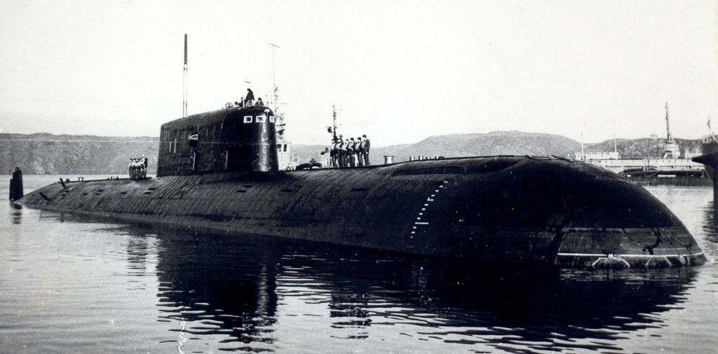
    I am as mentioned finding a divergence between what the drawings say and what the photos of the Komsomolets, show. The bow section with the blisters, are they as pronounced as the drawings suggest or is the deck more raised? For this I have had lots of feedback for which I have been grateful. I have mentioned my decision earlier and these series of photos show me using the templates for the bow front view template showing the pronounced blisters. I will not make them as pronounced.

    I have taken time to modify the overall shape of the blisters. This involves adding more filler and using a template that feature a cut out of the blister and placing it over the top of the blister and tracing around it. Then making sure that they match up and sanding accordingly. I have also used a blade to shape the front end of the blister, marking out with lines to make sure they both line up.

    Anyway, enough for now.

    David h

    Comment

    • Peter W
      Captain
      • May 2011
      • 509

      #47


      try this site David I have found some Mike pics that I have never seen but can't upload the
      Via my phone.

      Peter

      Comment

      • Peter W
        Captain
        • May 2011
        • 509

        #48
        It may have worked ?
        Edit : it hasn't uploaded it to size where you can see it. David what is your email address and I will email you the pic. It may help answer a question or 2 if you haven't seen it that is
        Peter
        Attached Files
        Last edited by Peter W; 08-07-2015, 05:59 PM. Reason: I am an idiot

        Comment

        • HardRock
          Vice Admiral
          • Mar 2013
          • 1609

          #49
          Hey Peter. That picture is as small as an Australian cricket score!

          Comment

          • Peter W
            Captain
            • May 2011
            • 509

            #50
            I was using my phone to upload it but it won't let me make it bigger. I will try on the pc later.

            Peter

            Comment

            • Peter W
              Captain
              • May 2011
              • 509

              #51
              Click image for larger version

Name:	image_30128.jpg
Views:	157
Size:	18.4 KB
ID:	109340
              hopefully some one can make this bigger....please it is a reasonable res picture but I am struggling to get this format

              Peter

              Here is the image URL http://bastion-opk.ru/VVT/685_2014_01.jpg
              it is a 1413 x 697 pic so good for detail.
              Last edited by Peter W; 08-08-2015, 10:22 AM. Reason: I am an Idiot

              Comment

              • Davidh
                Captain
                • Nov 2010
                • 719

                #52
                Thanks Pete,

                This photo has been an important one for me from the start. I would kill for some really good dry dock pics though..

                Dave h

                Comment

                • Peter W
                  Captain
                  • May 2011
                  • 509

                  #53
                  I'm still on the look out for you, having Google translate helps because all the best pics come from Russian sites.

                  Peter
                  Last edited by Peter W; 08-09-2015, 07:03 AM. Reason: I am an idiot

                  Comment

                  • Davidh
                    Captain
                    • Nov 2010
                    • 719

                    #54
                    Hello all,

                    Thankyou to those people who have left comments and have helped with pics. Keep the ideas coming.

                    The blisters and bow bulges at the front are an ongoing thing and will probably take up more of my time over the next couple of weeks as I come to a final opinion regarding them. I will probably go with the compromise that I outlined earlier with regards to the slight raise in the section between the two bulges, yet tone down the bulges just a little bit.

                    In the meantime I have decided to start looking at a different section of the boat. The sail / fin is the most prominent structure other than the hull of course and so though that I would have a go at starting it's development. Komsomolets has a very long low Fin. It's like the Sierra, and the Oscar, and in keeping with so many soviet designs there is the escape chamber that takes up so much room in about the middle of the design. Although I haven't paid a huge amount of attention just at the moment to the escape module design, it is in my opinion, pretty clever.

                    Once again I have decided to cut two sides to the fin and would create two pieces that I could make split moulds from. They will be the first sail design masters that from the outset will be used to create RTV silicon moulds. I am not going GRP hardshells for this one. I recently took out the Resolution sail halves and re-tooled them using silicon and seriously, the improvement in fidelity is a no brainer. RTV silicon has seen a quantum leap in the quality of my mould work. I need to update "tool time" in "hints and tricks" to reflect this. Once you have started using RTV Silicon you won't look back. The silicon I use just needs a hardener added to the catalyst to get a nice thick paste that you can work up vertical surfaces. I just need to get the hardener, unfortunately here I cannot buy any less than about 500g-1Kg of the stuff. I only need about 50g.

                    I drilled two holes underneath the bottom of the sail. these two holes are skewed up and into the other side so they both hold together. This allows me to work on both pieces as one and make sure they are symmetrical and also that edge detail meets exactly where it should. I them spent a bit of time getting the symmetry of the overall halves right. Making sure that the tapers are right in the right place.

                    I intend on producing a separate top piece of the fin. this will have the detail for the masts, scopes, deck and the escape pod. Lots of detail here. As can be seen by the cut out of the fin top there is plenty of fin detail that is known of this boat. All you then have to do is put the sail on top of the hull in the right spot in the widened deck section in the middle and in no time it's starting to

                    "look like mike"..... I think.!

                    David H Click image for larger version

Name:	nice sheen.jpg
Views:	80
Size:	48.2 KB
ID:	109432 Click image for larger version

Name:	sanding and primer check..jpg
Views:	59
Size:	46.5 KB
ID:	109433 Click image for larger version

Name:	two part sail-fin sanded down to size.jpg
Views:	64
Size:	45.8 KB
ID:	109434 Click image for larger version

Name:	always,  the check for symmetry..jpg
Views:	65
Size:	47.7 KB
ID:	109435 Click image for larger version

Name:	top of sail profile.jpg
Views:	66
Size:	49.3 KB
ID:	109436 Click image for larger version

Name:	side view with sail.jpg
Views:	57
Size:	49.2 KB
ID:	109440 Click image for larger version

Name:	side view with sail.jpg
Views:	60
Size:	49.2 KB
ID:	109441 Click image for larger version

Name:	rear view of fin reflection and deck fillet.jpg
Views:	66
Size:	49.1 KB
ID:	109437 Click image for larger version

Name:	Nice low bow angle. Like the well known photo of the full size..jpg
Views:	96
Size:	49.8 KB
ID:	109438 Click image for larger version

Name:	_DSC4116.JPG
Views:	62
Size:	50.6 KB
ID:	109439

                    Comment

                    • bwi 971
                      Captain
                      • Jan 2015
                      • 896

                      #55
                      Originally posted by bwi 971

                      After studying the pictures it seems they were always positioned iwo the hull sonars, I believe they have something to do with the applying the GRP or something lookalike, see picture below as example of the lookalike stuff.
                      Came across a Russian site with a note to the pontoon pictures:

                      Подготовка с пуску АПЛ "К-278". Прямоугольные конструкции - понтоны для уменьшения осадки:
                      Preparing to launch submarine " K- 278 " . Rectangular design - pontoons to reduce rainfall :

                      Grtz,
                      Bart
                      Practical wisdom is only to be learned in the school of experience.
                      "Samuel Smiles"

                      Comment

                      • Davidh
                        Captain
                        • Nov 2010
                        • 719

                        #56
                        Hi All,

                        Thanks Bart, but I'm not quite sure what you are talking about with the pontoon pictures.

                        I have been away all week taking a group of students from my school on a hike from Wollongong to the Sydney Opera house. About 120km, to raise money for charities. My legs are stuffed!
                        So I have been a bit out of the loop however I have an update none the less from some work that I did a week or so ago.

                        I have been doing a little bit of consolidation and simply checking that all the dimensions and surfaces are right. I have been particularly looking at the overall size of the sail and making sure that the overall dimensions are right. I have been paying attention to the base of the sail to make sure that the overall shape of the sail at the base allows for a consistent width of the deck that stretches around the side of the sail. On Komsomolets, this 'footpath' is quite narrow. I think it is only barely wide enough for one crew member to walk around the side of the fin. Once again I have only got photos taken from a distance. The Rubin design bureau has STILL NOT GOT BACK TO ME! Nor has the St Petersburg Submariners Club. In the words of Jeremy Clarkson 'How hard can it be?' Some detailed pics would be really useful right about now.

                        This has meant doing a bit more sanding of the top of the sail and to make sure that the according taper of the sail matches the drawings. I have also gone ahead and started doing the first bit of detail on the sides of the sail. I have decided to create the windows at the front by creating recessed sections in the front edges. I saw a technique that involved cutting back the area of material around where the widows are placed and then cutting out really small pieces of plastic from an ice cream container that would act and the windows. I then mix up some filler and paste over the area that was cut out. Pressing the plastic squares into the filler and wiggling them around a bit as I don't want air pockets, and allowing to dry. Once dried it was simply a case of sanding back as flat and as smooth as possible and then gently pulling out the two very small plastic squares to reveal the recessed section. I think they turned out O.K.

                        As mentioned before, I also have decided to raise the front section between the bow blisters. This was done with a slither of wood that was glued down in between the blisters and then filled over and sanded. I am happy with the compromise.
                        David h Click image for larger version

Name:	raised section between blisters at bow..jpg
Views:	68
Size:	46.1 KB
ID:	109582 Click image for larger version

Name:	sanding back filler around raised bow section..jpg
Views:	63
Size:	44.2 KB
ID:	109583 Click image for larger version

Name:	sanded bow and sail.jpg
Views:	66
Size:	46.7 KB
ID:	109584 Click image for larger version

Name:	primer on sail and bow.jpg
Views:	62
Size:	47.7 KB
ID:	109585 Click image for larger version

Name:	sail with windows on deck.jpg
Views:	65
Size:	45.0 KB
ID:	109586 Click image for larger version

Name:	sail with recessed front windows..jpg
Views:	60
Size:	43.3 KB
ID:	109587 Click image for larger version

Name:	side view with sail.jpg
Views:	60
Size:	49.2 KB
ID:	109588 Click image for larger version

Name:	general view of sail and bow section..jpg
Views:	68
Size:	50.5 KB
ID:	109589

                        Comment

                        • He Who Shall Not Be Named
                          Moderator
                          • Aug 2008
                          • 12256

                          #57
                          The quality of your work has improved a great deal, Dave. Looking good, Kiddo!

                          M
                          Who is John Galt?

                          Comment

                          • Davidh
                            Captain
                            • Nov 2010
                            • 719

                            #58
                            Thankyou David for the comments,

                            I have spent a couple of hours sanding the front bow and gradually working down to finer and finer wet and dry. Then giving it a coat of primer and the bow is looking ok. After this I mounted the hull once again on the register board and got it square. Then I could mark out the horizon line and then start looking at bow detail. The mike has was looks like two sonar arrays at the front. One below the mid point of the hull and a smaller one above it. Although I don't think the above one is because the torpedo tubes run right through it. I have started out by marking their location with a permanent marker and then will go over those lines with a scribing tool. Once again I am aware that having different materials will make the scribing tool behave differently and the etching may not be consistent. I know David hates this. He's yelling something about Ren-shape right now. I am prepared to live with this.

                            I had bought some styrene strips a couple of weeks ago. I was kinda guessing as to the exact size that would be required to get the right scale size for this model, I picked size 143, 1mm x .6mm So I spend a little bit of time gluing some on and looking at it. Turns out to be too big and really needed to get some smaller size material. I needed to get thinner square section. So I removed this railing strip and would apply it later. 132,
                            Click image for larger version

Name:	rear view with wet primer.jpg
Views:	70
Size:	49.7 KB
ID:	109690 Click image for larger version

Name:	side mike.jpg
Views:	70
Size:	48.6 KB
ID:	109691 Click image for larger version

Name:	deck rails too big.jpg
Views:	62
Size:	50.4 KB
ID:	109692 Click image for larger version

Name:	premature railings.jpg
Views:	76
Size:	49.3 KB
ID:	109693 Click image for larger version

Name:	marking bow.jpg
Views:	78
Size:	44.9 KB
ID:	109694 Click image for larger version

Name:	more bow marking.jpg
Views:	67
Size:	46.0 KB
ID:	109695 Click image for larger version

Name:	bow details mike.jpg
Views:	71
Size:	50.7 KB
ID:	109696 Click image for larger version

Name:	marking on board.jpg
Views:	64
Size:	46.2 KB
ID:	109697 Click image for larger version

Name:	register board marking bow sonar.jpg
Views:	69
Size:	43.9 KB
ID:	109698 Click image for larger version

Name:	_DSC4167.JPG
Views:	62
Size:	47.7 KB
ID:	109699 .75mm x 1mm As it turned out it would be premature as it would be difficult to scribe the deck detail and I could just see the rail coming off whilst doing so.

                            I am very happy with how the register board is working. It gives excellent consistent and accurate lines. I recently bought a very fine saw, it's like a fine Japanese saw and has no kerf (sideways bend on the blades). It makes an excellent scribing tool for long lines like the lower sonar array outline. I wish I could use it on smaller detail. I don't find scribing an easy thing. Sure the inconsistencies in the material don't help but finding just the right technique for me is an on going task.

                            Once I had scribed the overall bow detail I then would apply filler to the small areas in which I had overshot or missed. Then once again sand back and give spray of primer.

                            that's enough for now..

                            David h


                            Comment

                            • trout
                              Admiral
                              • Jul 2011
                              • 3545

                              #59
                              David,
                              Wow, that is really coming along. Where did you find the Japanese saw?
                              Peace,
                              Tom
                              If you can cut, drill, saw, hit things and swear a lot, you're well on the way to building a working model sub.

                              Comment

                              • greenman407
                                Admiral
                                • Feb 2009
                                • 7530

                                #60
                                Originally posted by Peter W
                                [ATTACH=CONFIG]n109340[/ATTACH]
                                hopefully some one can make this bigger....please it is a reasonable res picture but I am struggling to get this format

                                Peter

                                Here is the image URL http://bastion-opk.ru/VVT/685_2014_01.jpg
                                it is a 1413 x 697 pic so good for detail.
                                Well now, this is the least I could do for such a good picture as well as a fine building project:
                                IT TAKES GREAT INTELLIGENCE TO FAKE SUCH STUPIDITY!

                                Comment

                                Working...