Welcome to our forums. For the best in R/C submarine kits, components and accessories, be sure to visit the Nautilus Drydocks
If this is your first visit, be sure to
check out the FAQ by clicking the
link above. You may have to register
before you can post: click the register link above to proceed. To start viewing messages,
select the forum that you want to visit from the selection below.
Scratch Build Project 685 Plavnik K-278 Komsomolets NATO: Mike
Thanks for the feedback. Tom, to answer your question the saw I bought is from the U.S. I bought it at my local hobby shop in Newcastle (NSW). It is really thin and needs a handle that I will have to make sometime. It makes a really nice fine cut.
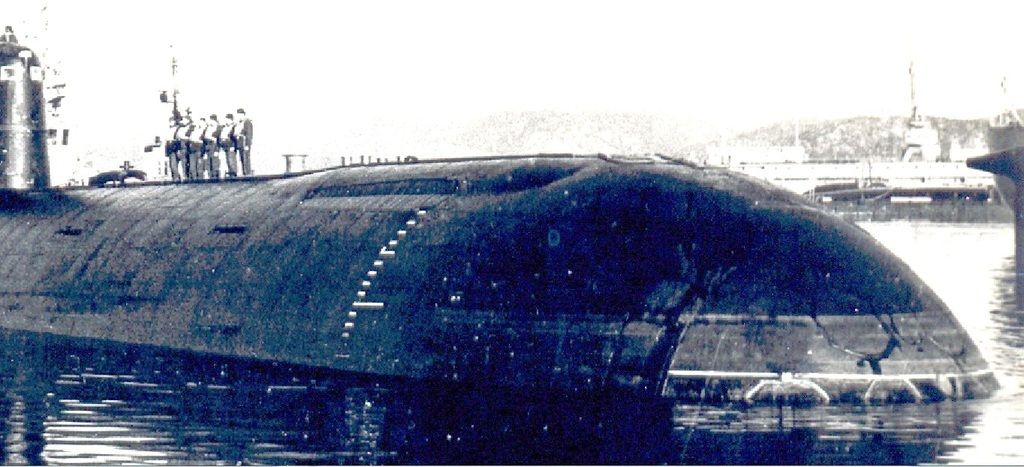
Thanks for the blow up of the above image. This is the best look at the front bulges that house the forward planes. A lot is revealed in this picture by the light reflecting off the surfaces. Still have not heard from RUBIN or the St Petersburg submariners club of not very helpful.
Once again I am on the slow and monotonous task of etching detail. I am coming across varying density of material that David always talks about and obviously with good reason. I am patient with this and will work through as best I can. I am practicing with various tools and am generally happy with how the scribe work is going.
I have made two templates specifically for the Komsomolets. They work well.
I have attached end pieces that I created in the workshop at school out of scrap Jarrah. These raise the hull of the boat and allow it to turn, just like it is on the lathe. Hmm,... how I want a lathe.... I can then scribe the vertical hull plates. these will be quite fine.
This brings me to a question that I have thought about a fair bit lately. You could probably write a thread on this in itself. With surface detail, how far should you go? Looking at David's work and the work of most builders, they go down to the major surface detail level of recessed panels railing and access panels. They do not bother with the weld lines of individual plates. I am guessing that the reasons may be the sheer increase in detail and work and that this detail may be lost in moulds. I think it certainly would be in GRP hard shells but how about silicon moulds? To what level do you take the detail?? Comments please.
The ultimate goal is to get as much depth in your cut with the least amount of sideways movement. Getting files that are fine enough to accomplish this is an ongoing quest. Once the etching is done down the forward section towards the bow then it is a case of laying down and gluing the styrene strip in place to simulate the safety track that run along the sides of the flat deck. As mentioned I originally used styrene that was too thick and ripped it up. eventually laying down thinner stock that is certainly an improvement. I would sand back a tiny amount of material and then with some super glue lay down the styrene in place. I bent some pieces but mainly just cut strip and glued in place. Once dried you can easily sand the edges so they are smooth and not sticking out.
You got to be pragmatic about the detail. Why bother with raised or recessed lines that will be lost to sand-paper or primer and paint? Most modern submarine hull weld seams are ground back to the surface of the plating, so you won't see it. Rule of thumb: if you see it in photos taken at a distance over twenty-feet from the subject, put it on the model.
Great work Dave. Thanks for the message. I'm away at present and I can't seem to be able to PM you on this platform. Back on 20 Sept. I'll call you then. Scott
The advice that you gave makes perfect sense. From a distance what are you going to see? I suppose if it's fine detail that you should only see right up close can be seen far off, it will make the model look cluttered and not accurate. I'm going to back off on the hull weld detail lines.
I have been spending a bit of time on the Sail/ Fin. The Komsomolets had a very long Fin. It was necessary to accommodate the emergency safety pod that is mounted about half way along the fin. I get the impression that this was a very good idea. There is a bit of documentation about it. It was used during the loss of Komsomolets in 1989 however there were problems and crew members died because of it. Aft of the emergency pod are all the masts. I have yet to look into them but will track down their NATO codenames, eventually.
I have decided to mould a separate top moulded piece for the sail. This will allow me to get decent detail on the top of the sail and also allow me to create a deeper section should I wish to create a section for the crew to stand on the bridge. I am erring this way. I have spent some time on the starboard side of the Sail and have etched in the hull weld details. I have done these finally and will add only light ones to the other side after taking David's advice. There is a reasonable amount of detail to add to the sides of the sail, including the doors and navigation lights. I also have the railings to put on. Originally I thought of using the same styrene as the deck but it's a little thick so I'm thinking of using some really fine brass wire. Very fine and light. Should come out OK in the silicon moulds.
The top of the sail was a bit high so I sliced off the top of the flat sail section. The radius of the top of the Sail starts immediately above the windows at the front. I then traced around the sail and cut out a thin piece of pine to then started bevelling the edges and detailing the top of the Sail. Rounded the edges and gave a coat of resin. Once this was done I could start drawings in all the etch detail in pencil.
I have made a couple of drawing of the sail and it's details to get positioning right. I have also taken a cut out of the plan view of the sail to get the details as accurate as I can.
I have been doing some more work on the fin. There is a lot of detail here and so I have spent a fair amount of time detailing it. I would say that attention is usually drawn to the sail as with the bow. As mentioned earlier I am going to cut a section through the front of the top of the sail to simulate the bridge area for the crew. In the following photos you will see the initial cut out of the profile that will then be extended further down when I make the mould for the top piece.
The main detail of the sail is of course the escape pod. A feature distinctive to Soviet and Russian Submarines. It was important that the lines of the escape pod on the side of the sail match up with the corresponding line son the top. This was the case with a few other details as the top view drawing does show some of the side surface as the sail is tapered upward.
I had to verify that the to hatches on the side of the sail were only on one side. The drawing that I have only shows one side and unfortunately the photo's of the other side of the boat aren't great. I have had no luck contacting those previously mentioned sources in Russia. They have been useless. The only detail on the port side that seems to be devoid on the other is the vertically extending cable line that protrudes out from the hull deck and up the side of the sail. I will be modelling this with styrene strip.
The next point of detail is the railing around the side of the sail. I could have used styrene however that would have looked a little big and ungainly. I have used some very thin brass wire from the local hobby shop. I simply sanded back a strip of area where it will be placed and super glued it down. There is railing along brief sections of the top of the sail and I have added railing there too.
Turning to the rear of the boat, aft of the sail would be a continuation of the front with railing and scribing in all the necessary details, including those wacky little torpedo shaped hatches. Does anybody know what they are for? Obviously torpedo related. I also had to work on producing a protruding rear hatch. This was made by cutting small piece of dowel and sanding it to the right size then gluing it to the rear of the hull. There would then be the usual round of filler. I have also had to create an raised hatch at the front of the boat. I have to do a bit more detail on these.
I am officially on holidays now for two weeks, Yay! So there may be a quicker turn around on progress....
Thanks for the reply. When you work with a design closely for a couple of months you get to know it really well. This drawing has the overall aspects reasonably true however I have seen a few inconsistencies. The drawings I have been working off I have checked as best as possible off the few photos I have and seem pretty good. This one does diverge.
The flat deck section around the sides of the fin/sail is way too wide. The overall deck looks a bit wide. I can't comment on the under hull. However thanks for the pic always appreciated.
I am currently working on the rear planes and on the model they are really tiny! They look disproportionately small...
Had a bit of extra building time having this week off. I thought I might re-ask the question as to what those torpedo shape hatches are on the main deck of most Russian subs. They are quite small but I have etched a lot of them lately. Does anybody know what they are for?
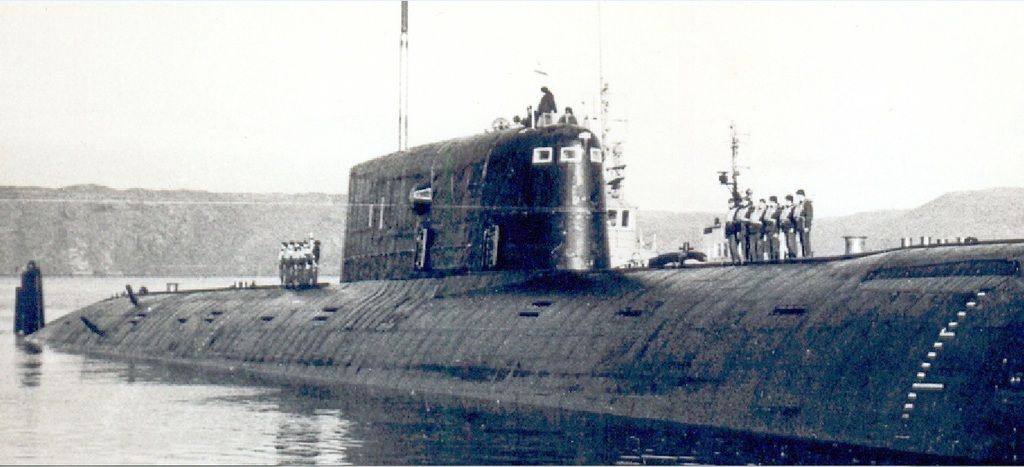
I have started making the inlet reactor coolant scoops. These are the big round ones found towards the back end of the likes of the Sierra, Charlie, Victor, Delta and finally Typhoon classes. All the drawings of Mike feature them as there is that one drydock photo of the mike where you can just see one sticking out in front of some boarding. Komsomolets has two per side , one above the other. I have been trawling the Subdriver forum for photos and been looking up the Russian Submarine ID page and for all the fantastic photos on that forum, and there are some rippers, I cannot find a clear photo of these round scoops up close. There are some of the narrow rectangular ones that you find on the Oscar and Akula but none of the big round ones. Does anybody have any good images of these?
So I started by cutting some dowel to length. I then decided to use my drill press as a lathe of sorts. Placing the pieces inside the chuck, turn on and attack with a chisel. I managed to cut a lip on the inner face that is the point of inlet. Then I finished off with some sandpaper. According to the drawings, the inlets mount on the hull with a teardrop profile. This means that I needed to cut out a profile with some thin Jarrah I then glued it to the lopsided, side of the scoop. Once done I could then apply the filler, then sand , sand, sand.
The challenge in making four is in getting them absolutely precise and all the same. This is still a work in progress. I will be making the silicon mould with all four. I intend on gluing a small styrene profile piece on the sides where the scoops will be mounted.
Oh, by the way I have entered the brave new world of selling stuff. I know that its not on the level with HWSNBN or J. Stadnick however I thought that maybe someone at the Gosford Sub regatta in a couple of weeks time may just be interested in purchasing my Resolution kit. Still a work in progress however for an experienced modeller this would scrub up nicely..
Had a bit of extra building time having this week off. I thought I might re-ask the question as to what those torpedo shape hatches are on the main deck of most Russian subs. They are quite small but I have etched a lot of them lately. Does anybody know what they are for?
I have started making the inlet reactor coolant scoops. These are the big round ones found towards the back end of the likes of the Sierra, Charlie, Victor, Delta and finally Typhoon classes. All the drawings of M [ATTACH=CONFIG]n110262[/ATTACH] [ATTACH=CONFIG]n110263[/ATTACH] [ATTACH=CONFIG]n110264[/ATTACH] [ATTACH=CONFIG]n110265[/ATTACH] [ATTACH=CONFIG]n110266[/ATTACH] [ATTACH=CONFIG]n110269[/ATTACH] [ATTACH=CONFIG]n110268[/ATTACH] ike feature them as there is that one drydock photo of the mike where you can just see one sticking out in front of some boarding. Komsomolets has two per side , one above the other. I have been trawling the Subdriver forum for photos and been looking up the Russian Submarine ID page and for all the fantastic photos on that forum, and there are some rippers, I cannot find a clear photo of these round scoops up close. There are some of the narrow rectangular ones that you find on the Oscar and Akula but none of the big round ones. Does anybody have any good images of these?
So I started by cutting some dowel to length. I then decided to use my drill press as a lathe of sorts. Placing the pieces inside the chuck, turn on and attack with a chisel. I managed to cut a lip on the inner face that is the point of inlet. Then I finished off with some sandpaper. According to the drawings, the inlets mount on the hull with a teardrop profile. This means that I needed to cut out a profile with some thin Jarrah I then glued it to the lopsided, side of the scoop. Once done I could then apply the filler, then sand , sand, sand.
The challenge in making four is in getting them absolutely precise and all the same. This is still a work in progress. I will be making the silicon mould with all four. I intend on gluing a small styrene profile piece on the sides where the scoops will be mounted.
Oh, by the way I have entered the brave new world of selling stuff. I know that its not on the level with HWSNBN or J. Stadnick however I thought that maybe someone at the Gosford Sub regatta in a couple of weeks time may just be interested in purchasing my Resolution kit. Still a work in progress however for an experienced modeller this would scrub up nicely..
Fingers crossed..
David H
Welcome to the party, Pal! (best line from the first Diehard movie). Good luck with sales.
You're quickly maturing as a Crafstman -- your MIKE is many steps ahead of your British FBM. Keep at it, Kiddo. Soon I'll be taking lessons from you.
As I have to replace my shark ones with these round ones I'm searching the WWW for pictures of them too.
This one is from a Typhoon. If you have others please post them.
Grtz,
Bart
Practical wisdom is only to be learned in the school of experience. "Samuel Smiles"


Comment