Walter type XVIIb scale 1:30

Collapse
X
 
  • Time
  • Show
Clear All
new posts
  • MFR1964
    Detail Nut of the First Order
    • Sep 2010
    • 1290

    #61
    Thanks,

    It's always a surprice if things work like i had inside my head, this build will be the result of all gained experience all those years, to give you guys some more, i've started to work on the servo's, placed the servo's in such way that they all can do their work without troubles, pictures.


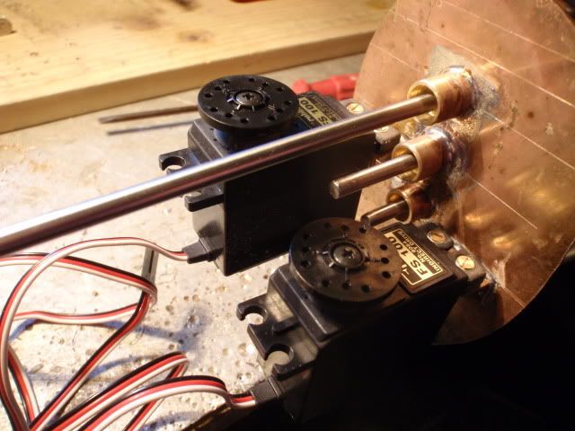
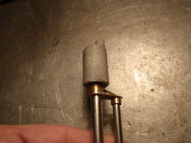
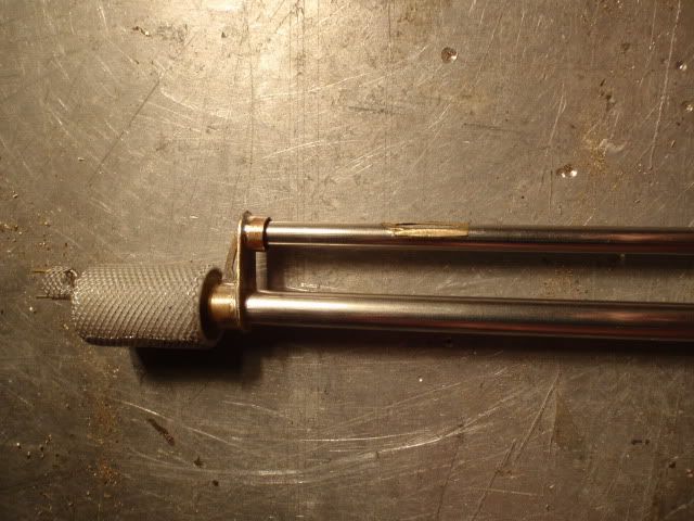
    The rear bulkhead with both the rudder and diveplane servo, have to make the couplers for the steeringrods.


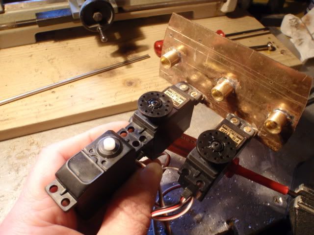
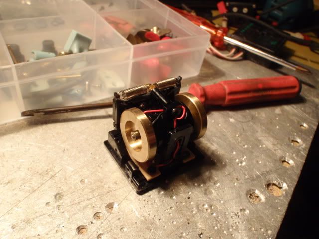
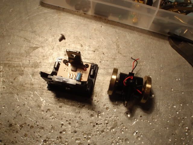
    The front bulkhead is a bit different, i need two servo's for the launchtubes and a third one for steering the strange stabilising wing, this arrangement seems to be the best.


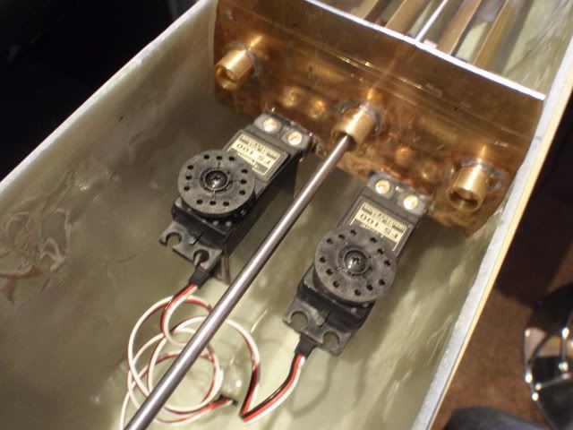
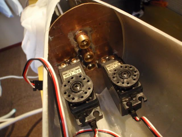
    Dryfitting both bulkheads inside the hull, next stage will be, making the connections to the rods, since you have movement around both axes i have to make a bit different connection, i'll copy the one from the V80, which is working fine.


    Manfred.
    I went underground

    Comment

    • MFR1964
      Detail Nut of the First Order
      • Sep 2010
      • 1290

      #62
      This week i decided to leave the servo's alone, and wanted to make something nice, it's not finished yet but you can see what it will be at the end.
      This kind of boat has a ringswimmer snorkel, the configuration is a bit odd compared to the other i've build, it consists from two stainless tubes, one for the intake, the other for the outlet, with the exit of the exhaust half way down the rear tube, see for yourself.


      All loose parts together, as you can see on the background, documentation is fundamental.


      Most work was to imitate what the germans call sumpf, it's a kind of wax coating to absorb the centrimetric radarwaves, in practice it didn't worked as it should, the wax released itself due to the salt water, later development was making the snorkelhead from resin products, i tried to imitate the wax matting with the use of a aluminum mesh which is used on a frying pan.


      First dryfitt to see if i have to alter some things, the length is much too long but that will be solved later.


      The most tricky part was, to make the insert into the stainless tube and replace it by the exhaust flush without to damage the stainless tube, made this from thin copper sheeting, my intension is to make the exhaust functional, want to connect one of the valves from the ballasttank to it, this way i've got two things into one.


      Still have to make some items which are placed onto the toppart, got to start up the lathe for that.


      Finally a dryfitt on the conningtower, used some tape to get me the right height accourding to the drawing.

      As you guys can see i don't follow the rules by building parts randomly, sometimes when i work too long on one part i get bored and want to see some result, at the end i'll need the parts anyway.

      Manfred.
      I went underground

      Comment

      • He Who Shall Not Be Named
        Moderator
        • Aug 2008
        • 12256

        #63
        That screen, from an anti-spatter cooking cover? Genius

        David
        Who is John Galt?

        Comment

        • trout
          Admiral
          • Jul 2011
          • 3545

          #64
          Manfred,
          Great work! How did you secure the screen? How did you handle the seam of the mesh?
          If you can cut, drill, saw, hit things and swear a lot, you're well on the way to building a working model sub.

          Comment

          • MFR1964
            Detail Nut of the First Order
            • Sep 2010
            • 1290

            #65
            David, don't tell She Who Must Be Obeyed that i've robbed the kitchen, i'm getting strange questions allready, and she is starting rolling her eyes.

            Tom, i've tagged it with CA, the only trick is, when you add the CA, give it a nice blow of air to keep the mesh free from clogging, i've done this all way around.
            There is a small seem, but what i know of the real pictures, they even added it into smaller patches, giving it countless seems, i made the wax matting from one piece to prefent the damage which can occur when hitting the snorkelhead, there all are allways little kids with greasy fingers which want to molest our models, so i try to make most parts kiddyproof.


            Manfred.
            I went underground

            Comment

            • MFR1964
              Detail Nut of the First Order
              • Sep 2010
              • 1290

              #66
              Finished up the last things on the snorkelhead toppart, had to add some items and make a sturdy connection for the rear stainless steel tube, for now it's in save storage for the future, next week will be running the gauntlett with the servo's, so i can test the tailpart for real.


              First stage was adding the front brass tube for fitting the snorkelhead, added a small bracket, which is also present at the drawings.


              Dryfitting the snorkelhead, the piece of brass tube at the rear stainless steel tube is not there at the original drawing, i had to make this concession for getting me a sturdy connection to glue the reartube tight, at the real thing there is a kind of flange, too flimsy at this scale to give me enough strenght for a good connection when glueing this part.


              Cutted the rear tube to it's length, the exhaust is now at it's final position, everything is not glued yet, because i still have to build a kind of lift for this little project, this way it's easier to handle when i want to alter things, so now it's back to servo time.


              Manfred.
              I went underground

              Comment

              • MFR1964
                Detail Nut of the First Order
                • Sep 2010
                • 1290

                #67
                The first bulkhead is tagged into it's place, first i want to glue it all around, and i've started something new, boggle your braines.

                I went underground

                Comment

                • He Who Shall Not Be Named
                  Moderator
                  • Aug 2008
                  • 12256

                  #68
                  Originally posted by MFR1964
                  The first bulkhead is tagged into it's place, first i want to glue it all around, and i've started something new, boggle your braines.

                  You cave-man!

                  That's an old Futaba rate-gyro! Hello!!!!! ... it's the frig'n 21st Century! You going to use the Hall-effect feed-back system for an angle-keeper or something like that?

                  David

                  David
                  Who is John Galt?

                  Comment

                  • redboat219
                    Admiral
                    • Dec 2008
                    • 2735

                    #69
                    Originally posted by MFR1964
                    The first bulkhead is tagged into it's place, first i want to glue it all around, and i've started something new, boggle your braines.

                    I've always wanted to know how they did angle keeping before there where MEMS. I kept reading about how some modelers used gyros as angle keepers but no informations on how they did it.
                    Please provide details of your modifications on the gyro.
                    Make it simple, make strong, make it work!

                    Comment

                    • MFR1964
                      Detail Nut of the First Order
                      • Sep 2010
                      • 1290

                      #70
                      David,

                      My pleasure, allready thought you like oldschool, and it might be cave man technique, but when done properly it will give you a true peroscope runner at very high speeds, have the same inside the type VIIC, which is running flawless for more than two decades.

                      Romel,

                      Keep looking, because this is the way to convert a oldschool mechanical helicoptergyro, i've learned it from my teacher and good friend, too many things are going down the drain, especially how to do certain things.


                      Next step is, remove the moving inner part, be carefull, there is a bearing inside, which you don't want to damage.


                      For removing the E motor you have to take off both fly wheels, use some gentle force and you got some spare parts for the future.


                      Tomorrow i'll rework these parts for making a pendulum, when finished i can put everything together, to be continued.


                      Manfred.
                      Last edited by MFR1964; 12-11-2012, 04:38 PM.
                      I went underground

                      Comment

                      • MFR1964
                        Detail Nut of the First Order
                        • Sep 2010
                        • 1290

                        #71


                        All parts together, used a PVC pipe 16 mm, which exactly fitts inside the moving part, made the other items from circuitboard.


                        By using a long M3 screw i can connect all parts.


                        A dryfitt of the finished pendulum, tomorrow i'll will place it inside the moving part and can rebuild/adapt the outer casing.


                        Manfred.
                        I went underground

                        Comment

                        • redboat219
                          Admiral
                          • Dec 2008
                          • 2735

                          #72
                          My initial impression was you'll be using the gyroscope as is.
                          So you essentially made a pendulum based inclinometer using the potentiometer from the gyro.

                          I wonder if you can use a servo checker in a similar way, put a pendulum on the control knob.

                          BTW, what do you use to damp out unwanted oscillations?
                          Last edited by redboat219; 12-13-2012, 05:09 AM.
                          Make it simple, make strong, make it work!

                          Comment

                          • Subculture
                            Admiral
                            • Feb 2009
                            • 2119

                            #73
                            I've not seen a potentiometer used- I imagine it would produce too much friction, plus it would wear out fairly quickly causing errors.

                            The ones I've seen use a hall sensor with a rare earth magnet. Some may have used optical sensors (photo transistors). Zero contact, so little to no friction, aside from the bearings of the shaft leading to the flywheel/motor.

                            Comment

                            • Subculture
                              Admiral
                              • Feb 2009
                              • 2119

                              #74
                              To damp oscillations, the pendulum was usually placed inside an oil bath.

                              I've also seen a levller with a small scrathbuilt gas damper fitted to the pendulum, which does the same job, but is a little more compact. Be interesting to see what manfred come up with here, looks like a slightly different approach.

                              Comment

                              • MFR1964
                                Detail Nut of the First Order
                                • Sep 2010
                                • 1290

                                #75
                                Romel,

                                Subculture is right about using the Hall effect, on the moving part there is a small magnet, the Hall sensor is placed on the frame near the magnet, the electronics translate what the position is of the pendulum, and will correct the angle of your boat.
                                In the past i've made a smaller one based on the servo failsaver, the potentiometer was replaced by a LDR, a little light was blinded by a small pendulum, so the resistance value varied, accourding to the amount of light which was projected on the LDR, all those components where placed inside a lightblocked box.
                                The only disadvantage was, you could not oversteer the failsaver without a complicated override switch, you needed two channels to make it work, the autogyro which i'm adapting now has the possibility to override, either by using the stick or your trim, so during the ride i can adjust the height very accurate, on my type VIIC i only use the trim to control the diveplanes giving me a perfect controlled ride underwater.


                                Did some more work on the gyro, inserted the PVC tube, and the guide for getting the screw exactly into the middle.


                                Placed the toppart and inserted the M3 screw, tapped M3 thread into the lower part, which allows me to screw it simply on.


                                The pendulum connected to the moving part, by using two slighty bigger shims it is tightened secure.


                                You can see the slighty bigger shim on top, the lower one is soldered onto the pendulum.


                                The matter of occillation can be solved by jamming some lead into the lowest part of the pendulum, the more weight you add at the lowest point the bigger will be the inertia of stopping, this way the pendulum will stop swinging, like subculture wrote, some guys use a oilbath for this, you can add a oilbath if needed, but in this configuration i'm driving my type VIIC for more than two decades, never failed me, it's a choice of your own which solution you like best.


                                Manfred.
                                I went underground

                                Comment

                                Working...