Walter type XVIIb scale 1:30

Collapse
X
 
  • Time
  • Show
Clear All
new posts
  • MFR1964
    Detail Nut of the First Order
    • Sep 2010
    • 1304

    #16
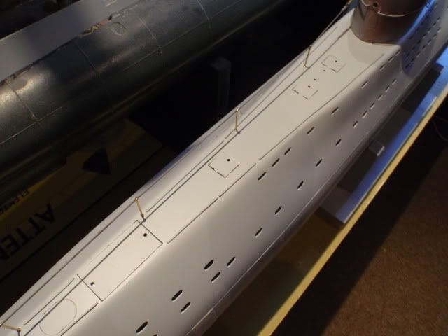
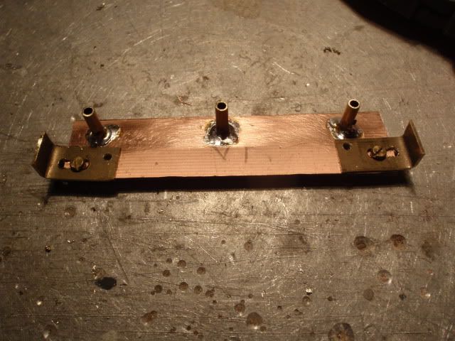
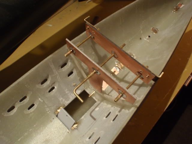
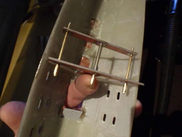
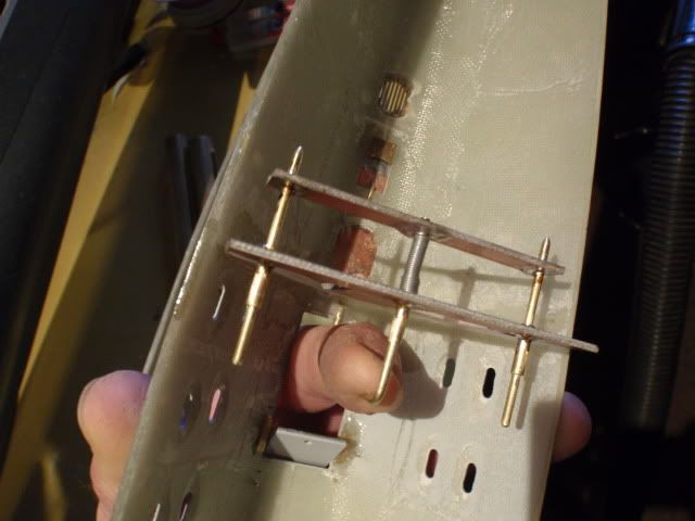
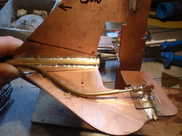
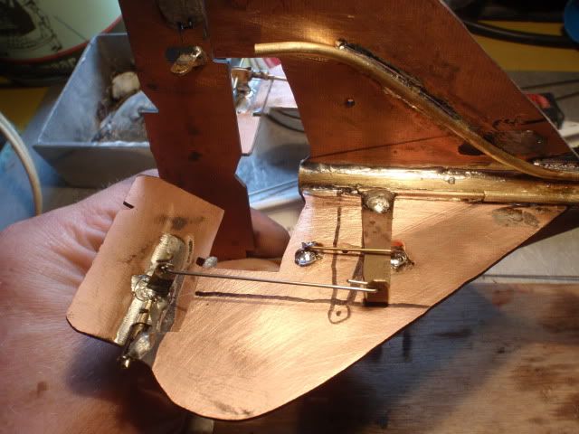
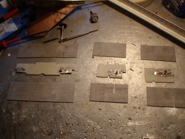
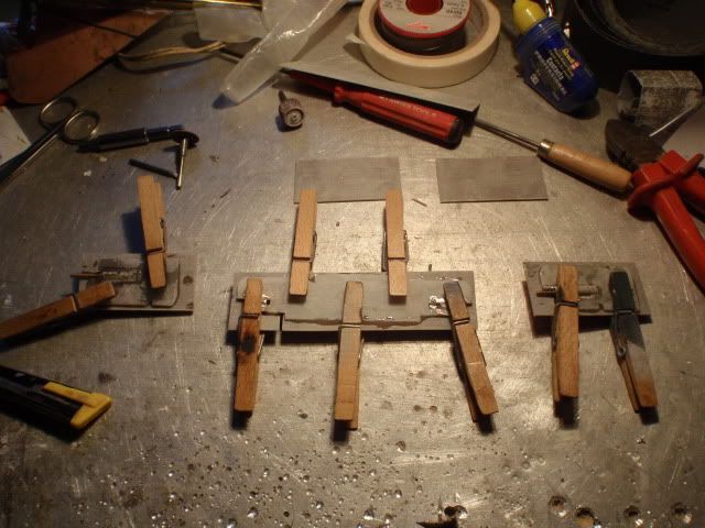
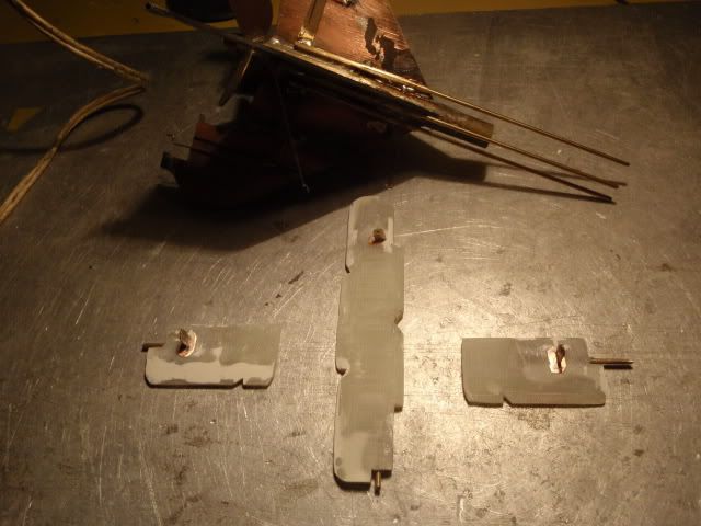
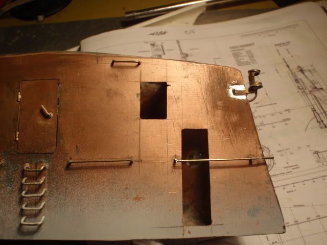
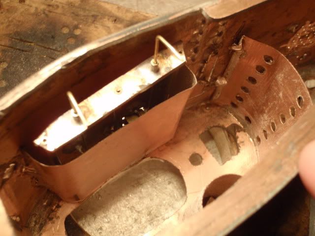
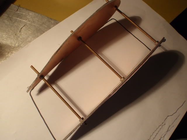
    Made a start with the lockingmechanism for the upper deck, used some pins at the rear and the front to secure it into it's right position.


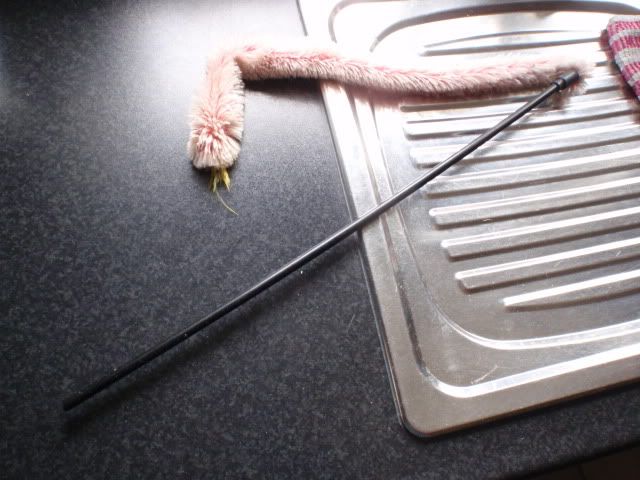
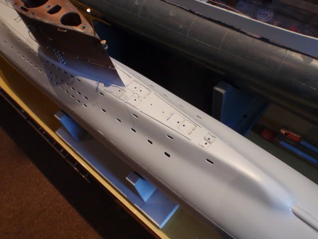
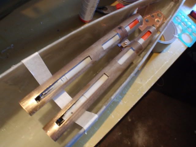
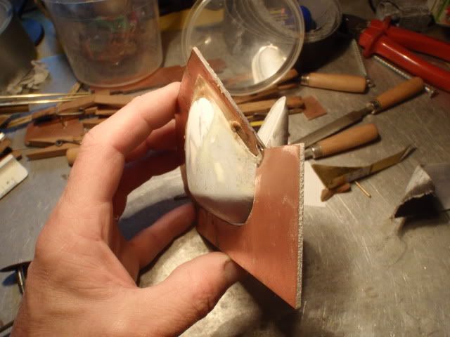
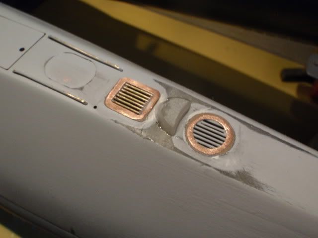
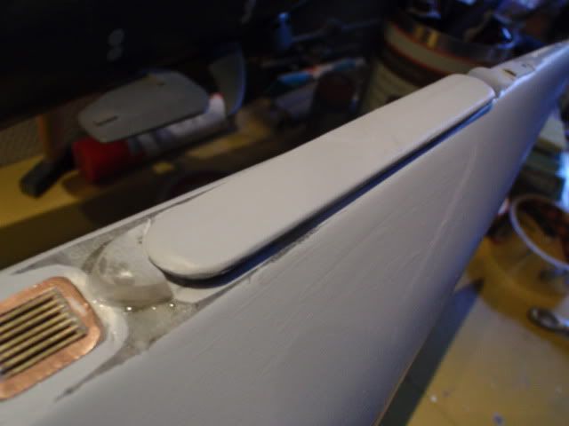
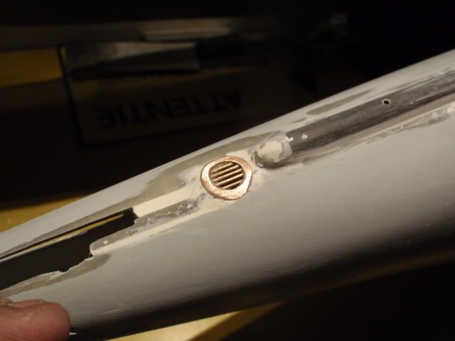
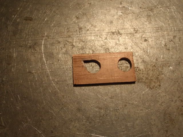
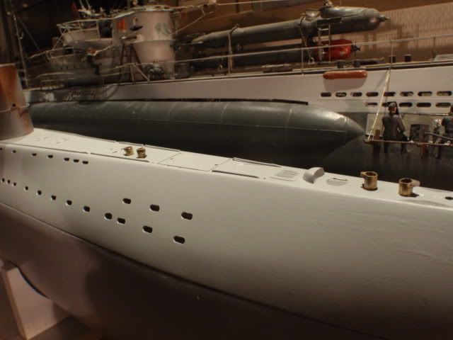
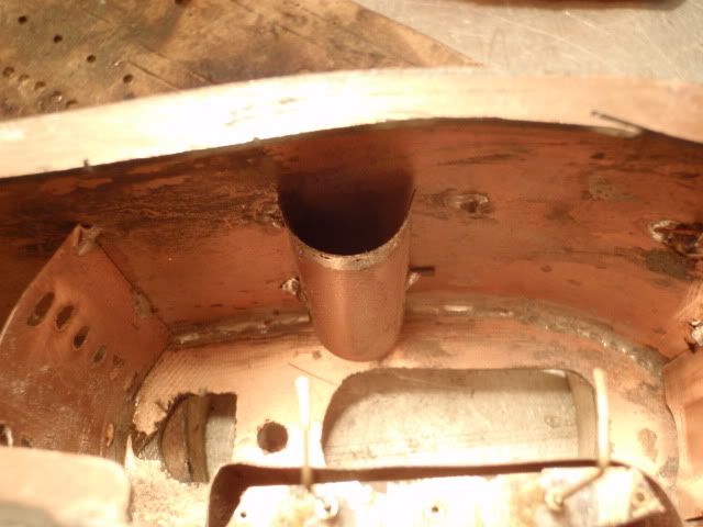
    Since the type XVIIb has a exhaust i wanted to use that for hiding the rear pin, used the tube from this cat toy because it had the right size.


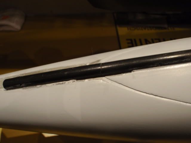
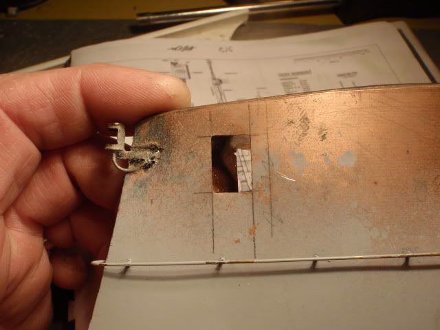
    Cutted it to the needed size and left some ends intact, cutted the slits into the deck and the hull and glued it together.


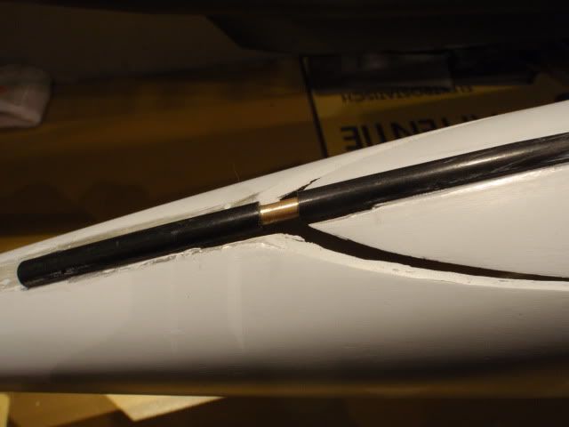
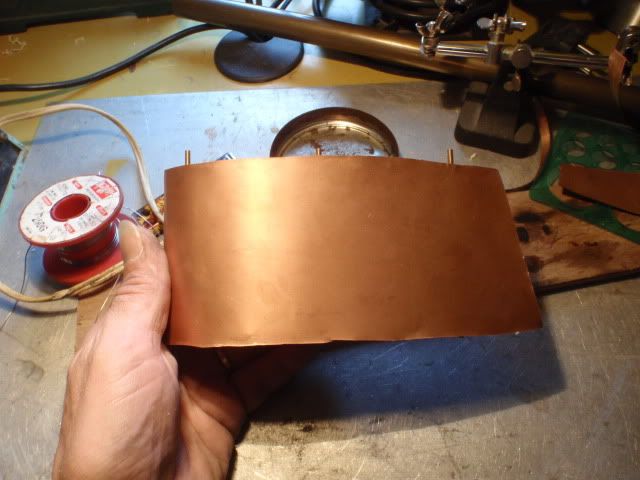
    Once dry it's possible to slide the upperdeck on or off the copper tube placed inside the plastick tube.


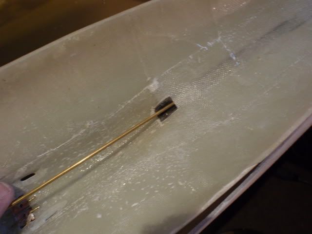
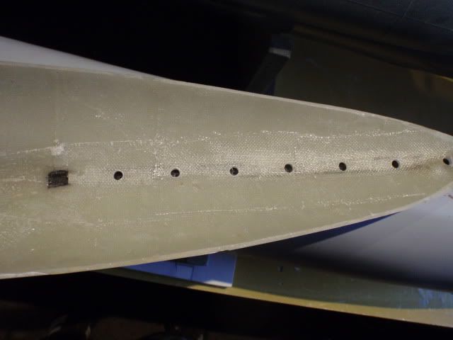
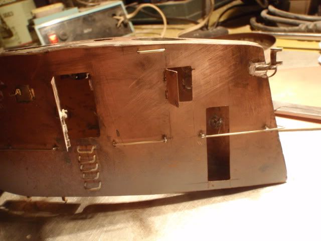
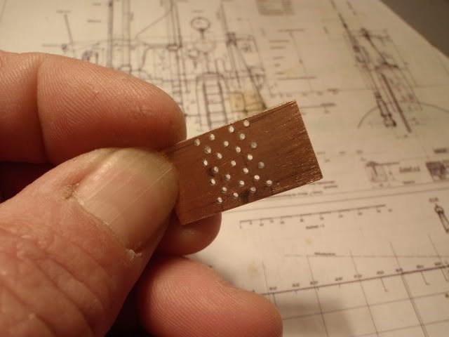
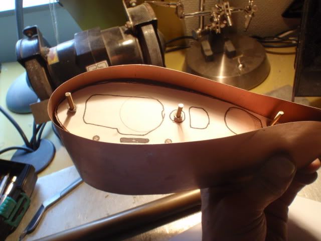
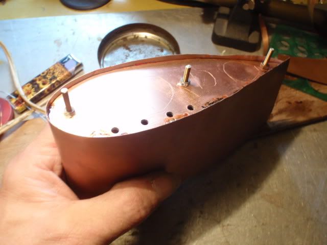
    To prefent getting airbubbles trapped inside the hollow exhausttube i drilled it open underneath the upperdeck and drilled some extra holes inside the tube itself and some bigger one's at the underside of the deck.


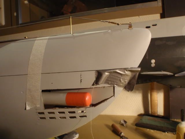
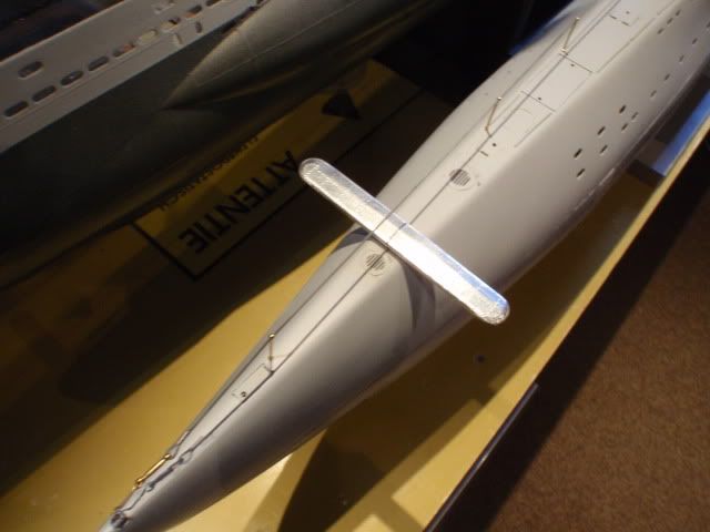
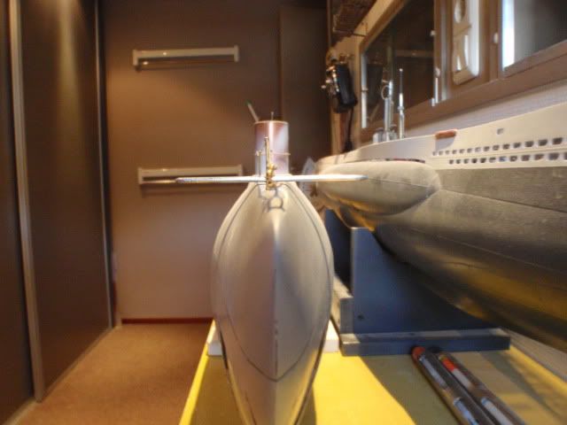
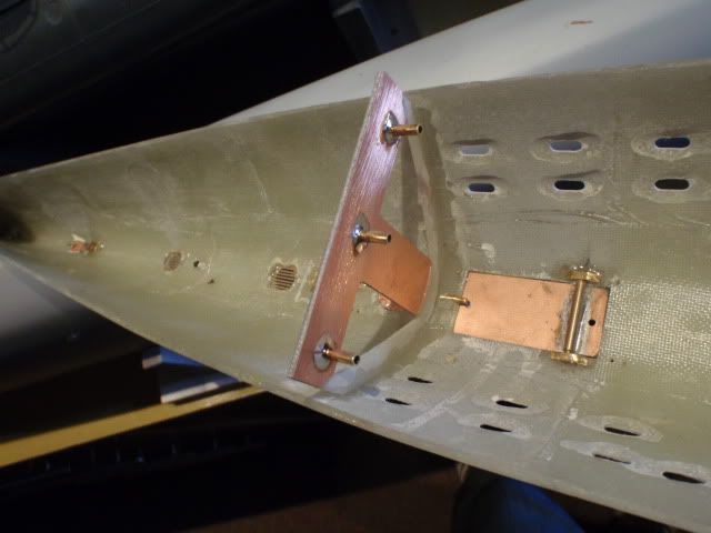
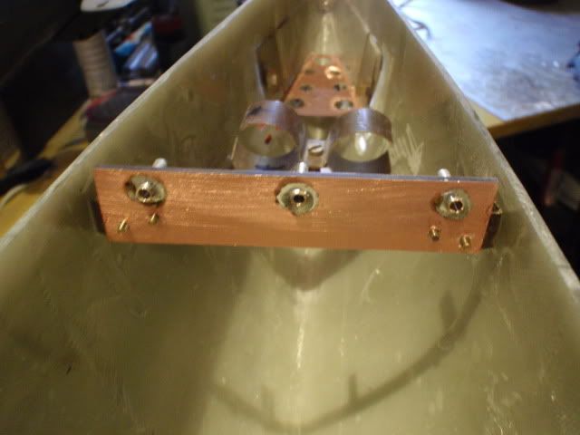
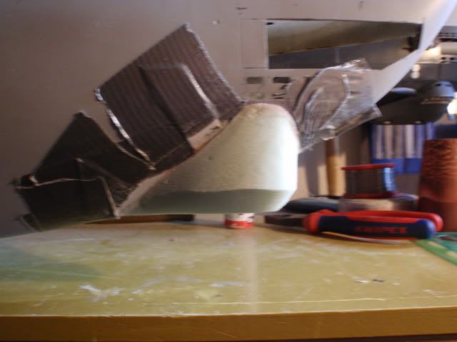
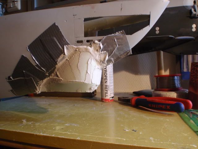
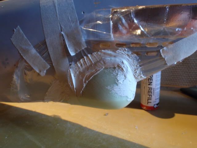
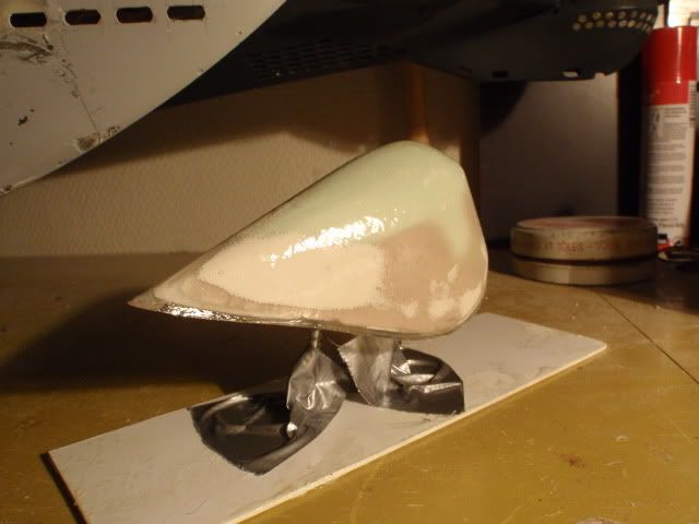
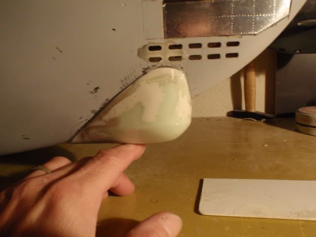
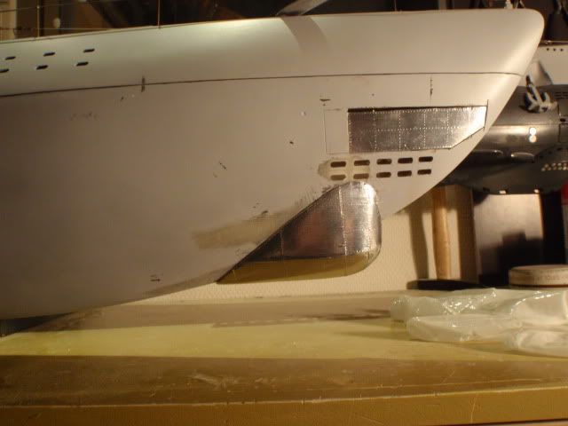
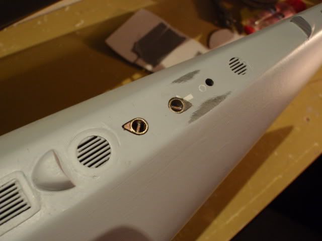
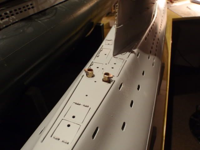
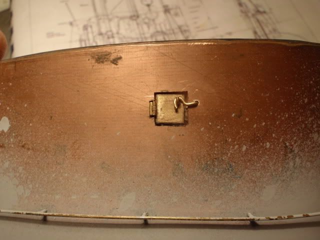
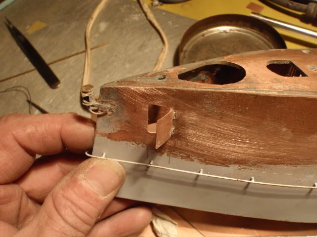
    Glued in the front pin and lined up the toppart with tape for letting it dry.


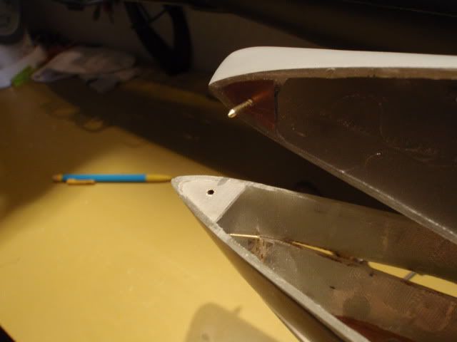
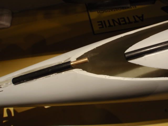
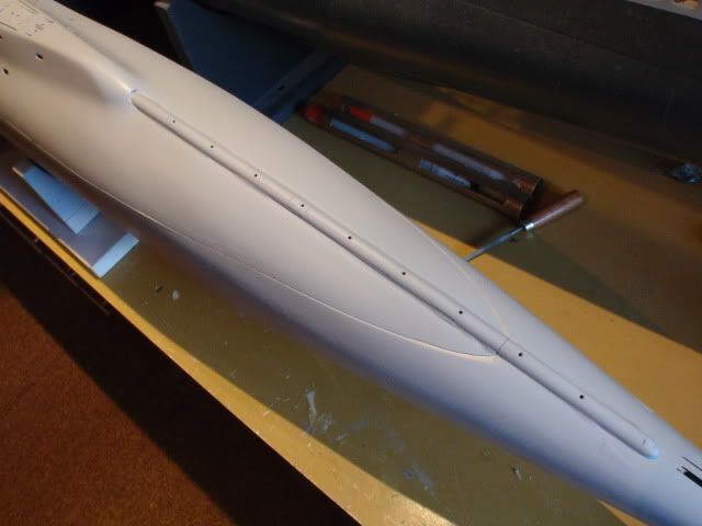
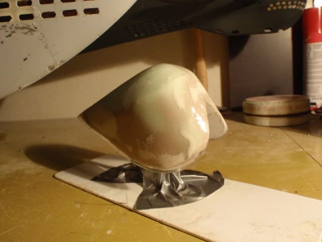
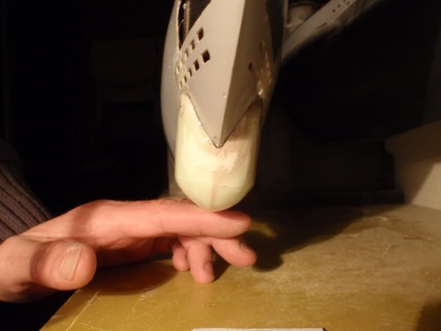
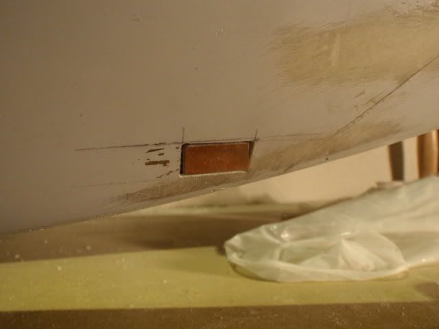
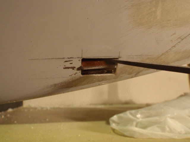
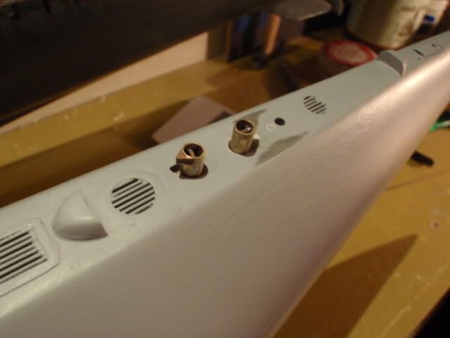
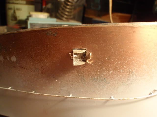
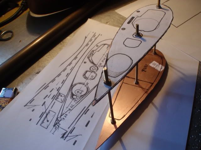
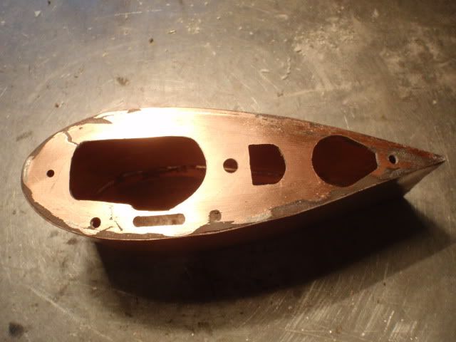
    Once dry i have me a pin and a tube glued at the bowpart.


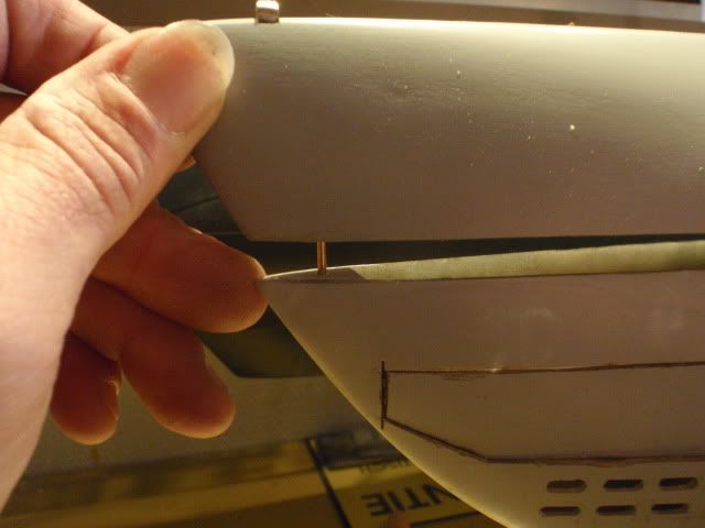
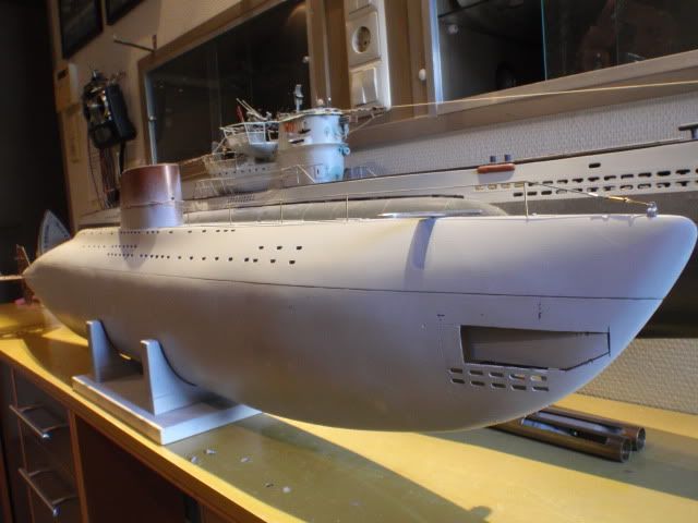
    The aim was to get me a centeringpin, so each time you put the upperdeck on the hull part it will be in the same position, adding the lockingmechanism will secure it to the hull.
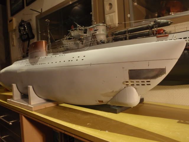
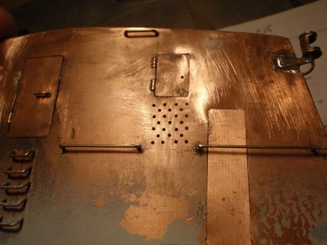
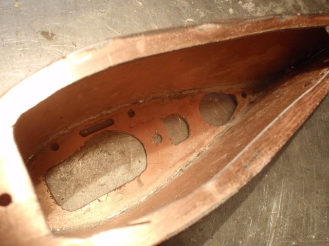
    The lockingmechanism itself is the next part i have to build, it will be located at the biggest front hatch.
    I went underground

    Comment

    • MFR1964
      Detail Nut of the First Order
      • Sep 2010
      • 1304

      #17


      Gave the boat a coat of primer to see how she will look with a grey colour, with primer you always will see the spots that have to be filled and sanded, gives me a idea how much work there still is.


      Builded up the stabilisingwing with multiple layers of circuitboat, and sanded it into it's shape, also gave it a aluminum foil coat, this way i can add the rivets, giving me more details.


      Did the same with the torpedodoors, adding the rivets is done by slightly pressing a old ballpoint into the foil.


      Some progress on the torpedotubes, cutted out the ventholes, still a lot of work has to be done before i've got me some functional tubes.


      This is where i stand now, she is starting to look like the real one, still have to make the sonardome at the bow, that on itself will be a adventure to build, this weekend i'll have a go at the lockingmechanism, all parts are ready to be placed, pics will follow.
      I went underground

      Comment

      • He Who Shall Not Be Named
        Moderator
        • Aug 2008
        • 12289

        #18
        You're taking us all back to school with this work. Most, most instructive! Thank you for sharing.

        David
        Who is John Galt?

        Comment

        • jlday1256
          Lieutenant
          • Jun 2011
          • 78

          #19
          Man! Tube from a cat toy! You are always thinking...
          Doodah
          If you ignore the problem long enough, it will go away. Even flooding stops eventually!

          Comment

          • MFR1964
            Detail Nut of the First Order
            • Sep 2010
            • 1304

            #20
            Thanks guys,

            I like the comparison with school, each time you start with a part of this sub, you have to learn how to do that, on the final pics it's always looking ok, some times i succeed at once, but like most builders i also have a learningcurve how to do certain things.
            I have a strange way of building, always busy with different components of the sub, i never use a schedule how to build a sub, only with building the plug, mold and hull you have to follow this.
            All other components are build randomly, i learned to do this from a good friend of mine, this way you will never get bored, building this sub will take two years, the type VII i've got took even longer, started in 1988 and finished her two years ago.
            Yeah, the tube, it suddenly popped my mind, i allready gave up, because the size i needed was not availble, suddenly, while playing with the cat it struck me, i took it to the shop and took a measurement of it's diameter, it was a perfect match, with this kind of hobby a stroke of luck is allways welcome.
            Hm, i'm getting dizzy from all those letters, gonna sniff some glue.
            I went underground

            Comment

            • greenman407
              Admiral
              • Feb 2009
              • 7530

              #21
              I am impressed. I thoroughly enjoyed reading this thread. I will now go back to my thread with hat in hand.
              IT TAKES GREAT INTELLIGENCE TO FAKE SUCH STUPIDITY!

              Comment

              • MFR1964
                Detail Nut of the First Order
                • Sep 2010
                • 1304

                #22
                Thanks Mark,

                There is still a lot to do before she will become the sub i have in my mind, this weekend i've done the lockingmechanism,


                The first bracket i've glued in, this will hold the springmechanism.


                The receiving part with adjustable brackets, so i could adjust it to the shape of the lower hull.


                Made the sliding pins and the second part, included the lever that will lock/unlock the toppart.


                Added the small spring that will slide the pins into the receiving part.


                By pulling the lever you retract the pins, once the upperpart is placed on the hull the spring will take care that the pins will extend.


                The pins will insert into the receiving tubes, i can remove the bracket by removing the M2 screws, i've done that this way, because in the nosepart it will become crowdy with the torpedotubes.


                Also made a start with the passive sonardome, the basic shape is made from styrodure, she will be covered with wallfiller to get the shape better, want to make a plug first and turn this into a mold, like the type VII i want to have a hollow example, gives my the oppertunity to fill it up with lead when needed.
                I went underground

                Comment

                • MFR1964
                  Detail Nut of the First Order
                  • Sep 2010
                  • 1304

                  #23
                  It took me some weeks but the sonardome is finished, also added some other items to the boat and started with the sternpart, due to the amount of pictures i'll split the update into two parts.


                  Applied some cheap wallfiller to get the shape better.


                  After sanding down the wallfiller i gave her a layer of glassfibre and epoxy, added her back to the bow by using the foil method, to give me a better transition between the dome and the hull.


                  After sanding down this layer of filler i gave her the second layer of glassfibre and epoxy, giving me the final shape.


                  Dryfitting the dome onto the bowpart, did this several times to insure the fit was allright


                  Due to the shape and angles of the dome making the mold become tricky, decided to use circuitboard for the base, which i could solder at the right angle to support the mold.


                  Building up the mold, the first 2 layers where thin glassfibre to catch the shape right, after that adding some thicker glassfibre gives me more thickness to the mold.


                  I expected more trouble with splitting this mold, but she came out real easy, cleaned her up and made me my sonardome.
                  I went underground

                  Comment

                  • MFR1964
                    Detail Nut of the First Order
                    • Sep 2010
                    • 1304

                    #24


                    This is the final product, added the aluminum foil to get me more detail, it was a bit tricky with all those curves but after several times i succeeded to get it right.


                    Placed at the bow at the right position, secured it with a simple screwconnection, used it before with the type VII.


                    Since there are no floodholes under the waterline i added some functional hatches, followed the shipyard drawings for the right position.


                    Primed the sonardome and sanded the bow for some more primer, you can barely see the screw securing the dome, have to drill out the hole to let it dissappear completely.


                    While working on the dome i got me some time to fiddle with the steeringproblem, this was the first version, works well but it takes to much room.


                    The second attempt, works also, but you need to much force to get everything moving.


                    The third attempt, this is going to be the winner, sliding action, runs smooth and more important it takes not a lot of room, so i can add the profile of the stabilisingwing quite easy.
                    Next step will be adding the profile to the divingplanes and rudders.

                    Greetings Manfred.
                    I went underground

                    Comment

                    • MFR1964
                      Detail Nut of the First Order
                      • Sep 2010
                      • 1304

                      #25
                      Next update about the progress on the type XVIIb,

                      Started adding some details on the deck, and some more work on the rearpart.


                      Replaced one of the hatches by a venthole and added the protectors for the stabilisingwing.


                      Also added another venthole near the exhaust, i discovered this one on the pictures i have.


                      Made a mold for making the holes where the bollards are positioned.


                      Drilled the holes and use some smooth files to make the right shape, pressed in the bollards in such way that they become flush to the deck.


                      Like the real thing you can extend or retract them by hand.


                      This weekend i started with the profile on the rudder and divingplanes, laminated them together with 2K glue, it has to dry over the weekend, so next week i can start with making the profile.
                      I went underground

                      Comment

                      • MFR1964
                        Detail Nut of the First Order
                        • Sep 2010
                        • 1304

                        #26


                        Used the dremel to get the basic shape, for making the final profile i added some filler.


                        Just like it's bigger counterpart it's possible to lock and unlock the nav lights.


                        With the cuttingdisk i made some extra hatches inside the conningtower, only this time i encountered some trouble with the railings, took away the part near the big hatch, and soldered it back after cutting the big hatch.


                        Used some small hinges to make them functional.


                        Added some small floodholes at the underside of the small hatches, only getting the prattern exactly the same would give some trouble.
                        The big hatch is simply soldered onto the conningtower, they could unscrew it if needed, i only have to drill some extra holes to imitate the screwholes.


                        Solved that problem by making a drillingmold, after the third attempt making the mold the pattern was allright for use.
                        I went underground

                        Comment

                        • MFR1964
                          Detail Nut of the First Order
                          • Sep 2010
                          • 1304

                          #27


                          Started with the internals of the conningtower, like the type VIIC they have teak wood inside to protect the crew against the cold steel, want to imitate that by using some styrene.

                          Greetings Manfred.
                          Last edited by MFR1964; 12-10-2011, 04:09 PM.
                          I went underground

                          Comment

                          • He Who Shall Not Be Named
                            Moderator
                            • Aug 2008
                            • 12289

                            #28
                            Manfred,

                            You are a detail nut of the First-Order! And your execution is simply marvelous; your unapologetic tour of the missteps, as well as the final product, is most instructive -- I've been following your thread like an eager school-kid chasing after a favorite instructor for more knowledge.

                            I note that you shot some primer at the unprepared copper clad GRP sail and brass railing -- subsequent handling revealed paint failure, as I would expect.

                            You may already know this, but if you wipe an acid laden rag over the copper (Ferric Chloride, the same stuff used to wash away the unprotected copper cladding during circuit manufacture ... what that substrate was designed for), and wait only long enough for the acid to oxidize on the surface (turns dark), then dunk the work in fresh water with a bit of baking soda dissolved in it and agitate the surface of the work with a brush to completely remove and kill the acid, you will achieve a copper (or copper alloy) surface much more receptive to the primer than if you simply scrubbed the metal with an abrasive before priming.

                            David,
                            Who is John Galt?

                            Comment

                            • MFR1964
                              Detail Nut of the First Order
                              • Sep 2010
                              • 1304

                              #29
                              Thanks David,

                              Hmm, detail nut of the first order, i presume that's a kind of title, can this be added at my profile?, misstaps are often not documented, for me it's showing how much research you have to do before it's working, i certainly know this sounds familiar to you, spraying the conningtower was more or less not intended, but it was still placed on the deck during priming it.
                              The conningtower itself is made of sheet copper 0.1 mm, and not copper clad GRP, it could be done, but using real copper sheet makes things simpler, and gives me a much lighter construction above the waterline., only used circuitboard for the upper and lower part.
                              I have to sand down the entire conningtower before i want to spray it into the primer, the chemical story you wrote is familair, done this a lot with aluminum when i worked in the aircraft industry, used offcourse a different kind of acid, i'll give it a try.

                              Greetings Manfred.
                              Last edited by MFR1964; 12-11-2011, 07:26 AM. Reason: GRP material
                              I went underground

                              Comment

                              • MFR1964
                                Detail Nut of the First Order
                                • Sep 2010
                                • 1304

                                #30
                                Thanks for editing my profile, i feel much more at comfort now, deep inside i've always knew that i was a nutcase, also have some pics from a few months ago, showing how i builded the conningtower.


                                Enlarged the Pfd file to my scale and glued it to the circuitboard, allowing me to saw the contours with the jewellers saw, used threaded rods to adjust it to the proper height.


                                Took a sheet of 0,1 mm copper and pre folded it to it's shape.


                                To keep it at his place just used some dots of solder.


                                Made a pre cut of the copper sheet to loose the excess material.


                                By cutting the conningtower open at the desired spots i could reach in with the soldering iron to make the final soldering.


                                Trimmed off all the edges and used a smooth file to get a better shape for the openings, the most left and right hole i've filled out, these were the points where the rods where placed.
                                I do have a mold for making a epoxy example, but i'm more worried about the weight issue, she stands rather high in the water, so every weight above will influense the CG while above the water.
                                Due to the copper sheet the weight will be as low as possible, and as a bonus you can solder every item easely on to the structure.


                                Greetings Manfred.
                                I went underground

                                Comment

                                Working...