Welcome to our forums. For the best in R/C submarine kits, components and accessories, be sure to visit the Nautilus Drydocks
If this is your first visit, be sure to
check out the FAQ by clicking the
link above. You may have to register
before you can post: click the register link above to proceed. To start viewing messages,
select the forum that you want to visit from the selection below.
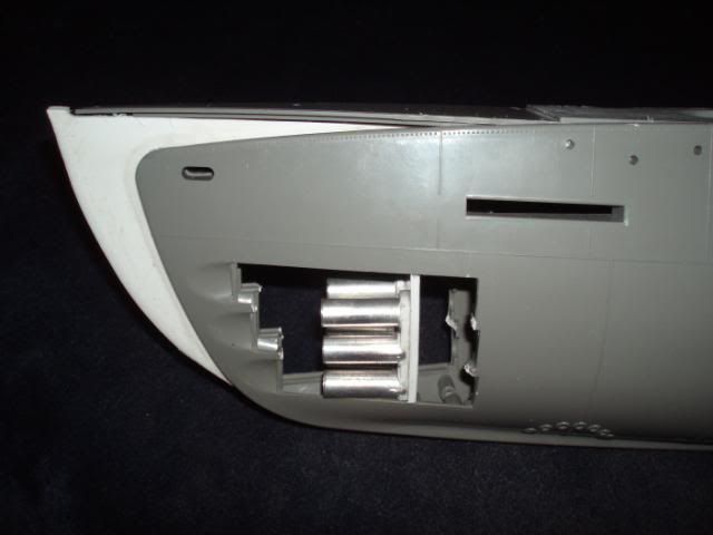
As you can see in the photos I had to remove the stock torpedo tubes and doors, they were one of the things that Lindberg didn't quite get right.
I made a new stand to hold the new torpedo tubes, the stand is made of 3mm plastic card and the 6 tubes are some K&S alloy tube. the new mounting was then fixed into place and set aside to dry and set up.
Last edited by oztruck; 04-10-2011, 09:51 PM.
Reason: spelling
Having sorted out the rear control surfaces and prop shafts it is now time to move to the bow of this beast. The bow is the area of this thing is the part that could make or break it as model. This is the area that the kit got all wrong, very wrong.
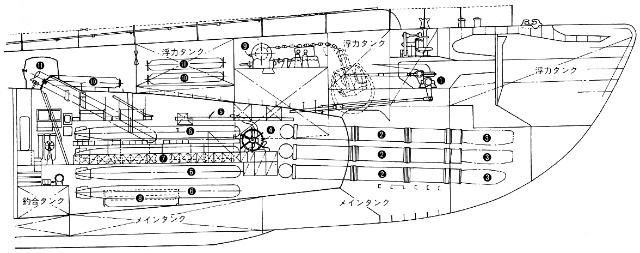
The first thing that I needed to start this part of the conversion was a drawing of the correct bow shape. I found some plans on the net and after a bit of playing around with my printer I was able to make a scale outline drawing of the shape that the bow needed to be.
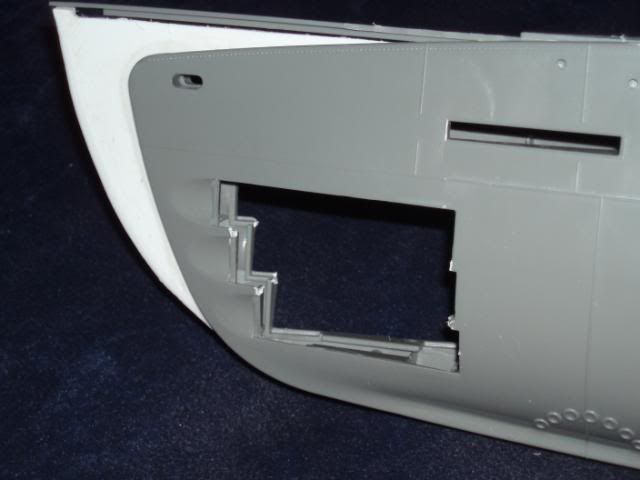
The paper outline was then transfered to a piece of 3mm plastic card and then cut out. The plastic shape was then placed between the 2 front hull half's to see what it would look like and any adjustments that might need to be made.
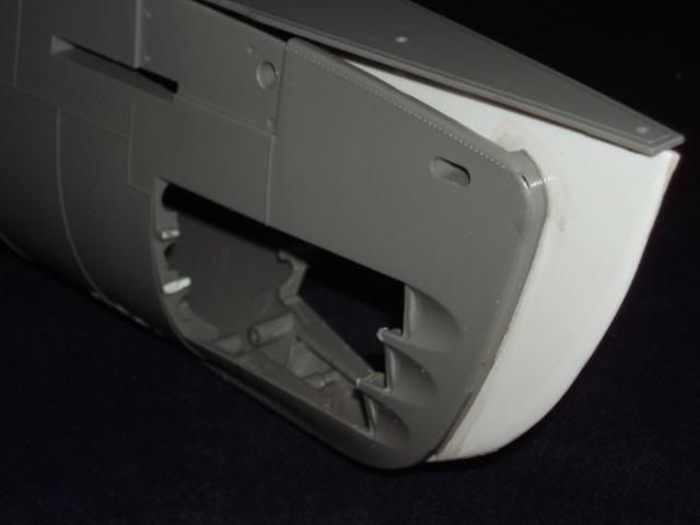
After a bit of adjusting, comparing with the plans, a bit more adjusting, back to the plans and a bit more tweaking I was at last happy with the basic shape/outline and permanently fixed the new bow outline in place using MEK a liquid glue I use to join plastics together.
The new work was then set aside and left to set and harden.
Not sure how far you intend to go in improving this beast but you may want to get rid of those toy like prop guards & build some yourself. Granted this is from the I-400 but the design was pretty much identical to the B/C types.
Also note the degaussing cable & rivet detail. These subs were of built of riveted lap-seam construction so if you really want it to look original... :wink:
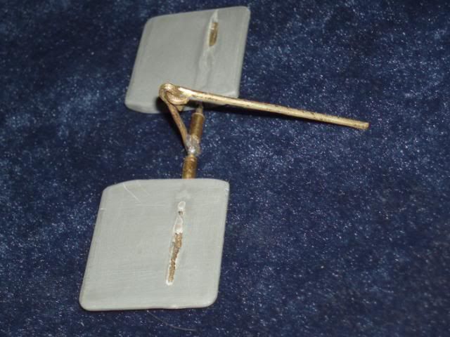
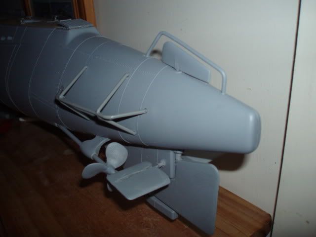
The next parts to receive attention are the rear dive planes.
First thing I had to do was make enough room inside the 2 rear hull sides to accommodate the linkages. The work went easy and fast using a dremmel because not much had to be removed from the inside surfaces to give me enough room for the linkages to move freely and with out any binding over the range of movement. When converting the kit parts to workable RC parts I used 1/16" K&S rod, cut to the correct length and bent and soldered together, then I just drilled a hole into each of the kit dive planes just a bit smaller than 1/16" and pressed the planes onto the shafts but not before making and installing some mounting bearings from some K&S tubing.
The next step was to drill out the mounting points to accept the new size shaft bearings and do a dry test fit. All went well and again a fairly easy conversion so far.
I did find it easier to mount the dive planes to the shafts after the linkage was installed into the hull.
The kit rear dive planes are not the correct size or shape but that will be resolved later on down the build. At the moment I just want to see if it can be done and without much effort.
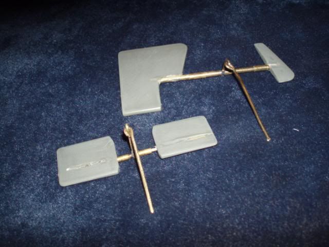
Being happy with the way the prop shafts turned out it is now time to look at the control surfaces.
The 2 piece rudder was easy, all I needed was a piece of 1/8 brass rod and some K&S tube to fit over the rod to act as bearings. The lever point was made using some 1/16" rod soldered to the 1/8" rod and bent to shape
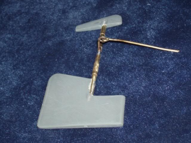
Using the kit parts I carefully drilled both parts of the rudder to accept the 1/8" rod. Cut the rod to the correct length slid the 2 bearings over the rod and then pressed the parts together lined it all up and fixed it to stop any movement on the rod.
The next part of the operation was to enlarge the mounting holes in the 2 rear hull half's to accept the bearings of the rudder shaft. I dry assembled the rear hull half's with the new rudder in place to check for any binding and alignment issues.
Don't worry "herrmill" they will now. I have found over the years of modeling as I am certain some of you have also found, that as soon as I build a conversion some one will release a kit of the same thing but better. Why should things change now?
Count me as well as being an interested spectator. I, too, was planning to do a B-type with one of their kits but now just sitting it out hoping they do release the other kit.
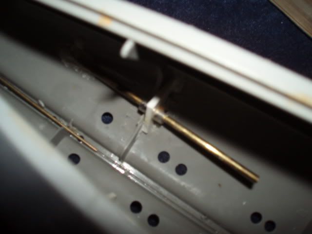
Once the bearings were lined up they were set in place with some 24hour Araldite on the inside of the 2 rear hull pieces. A thrust support plate was made to support the for and aft thrust loads on both prop shafts and they are held in place with 4, 2 each side 1/8" model aircraft wheel adapters. The idea of the thrust plate is to take any loading that might be placed on the shaft and transfer it to the hull instead of the drive line. Sorry about the photo (not enough light, old camera)
Yes! Good presentation so far. I too am interested in how you're going to r/c this beast. Eventually I'm going to do the same. If things slack off a bit around here I would like to finish that bow master for the thing.

Leave a comment: