I second that- Thanks David
these see photos are great.
David H
-
Create a new email address and open a second photobucket account - pour out that wisdom!
Leave a comment:
-
-
Holy data storage Batman! David, I wish I had not found the root of your photobucket.... http://s262.photobucket.com/user/dmeriman/library/
I am going to be spending hours pouring over this. What a knowledge dump you put there. Thank you.Leave a comment:
-
I'm home and back in the dungeon.
Some teaser shots of PJ tooling:
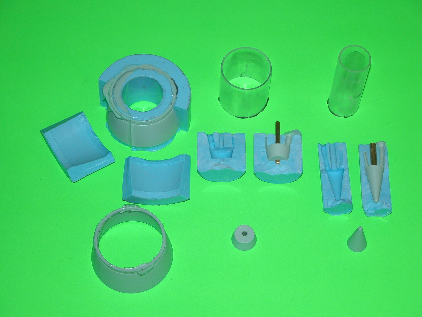
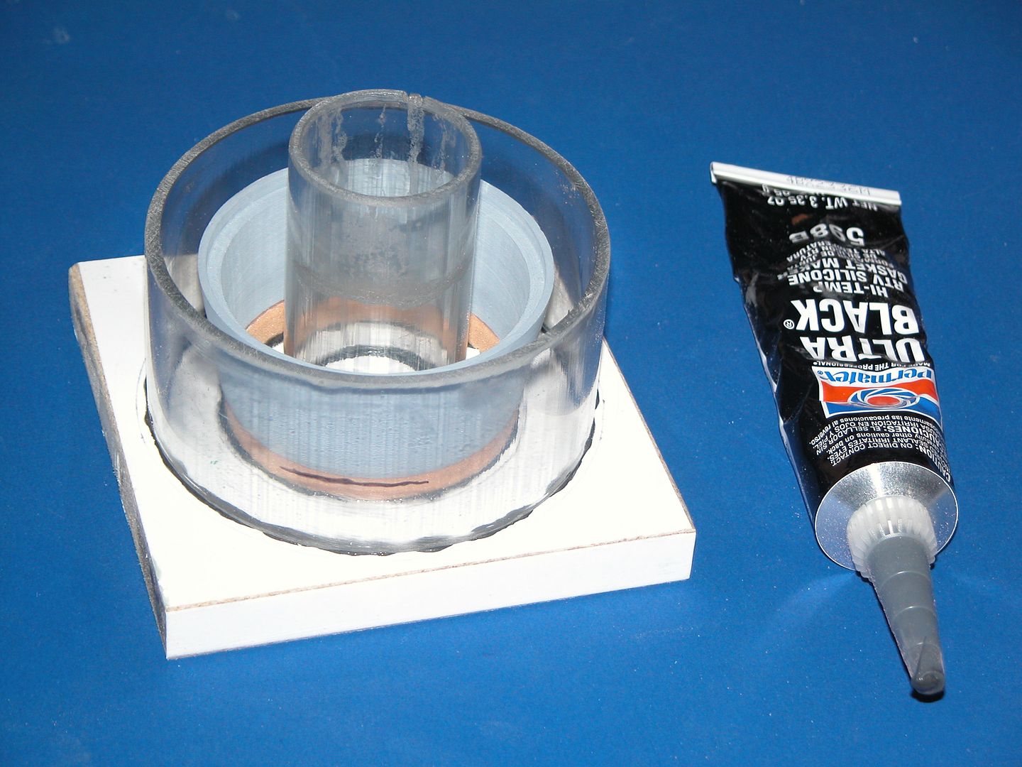
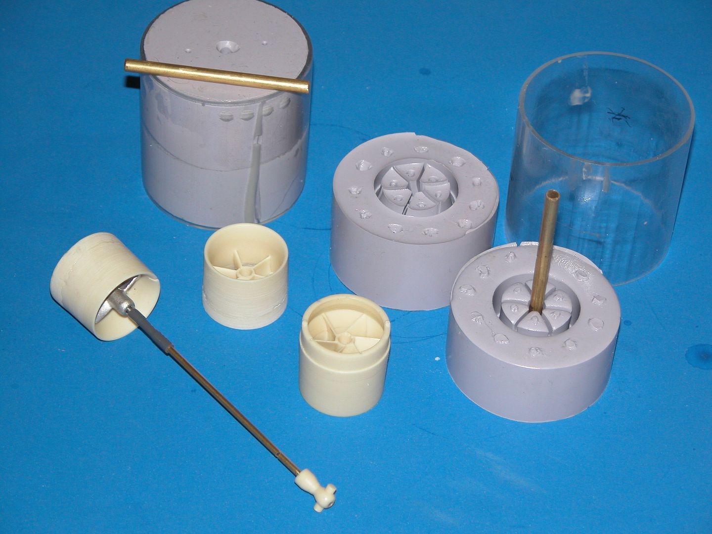
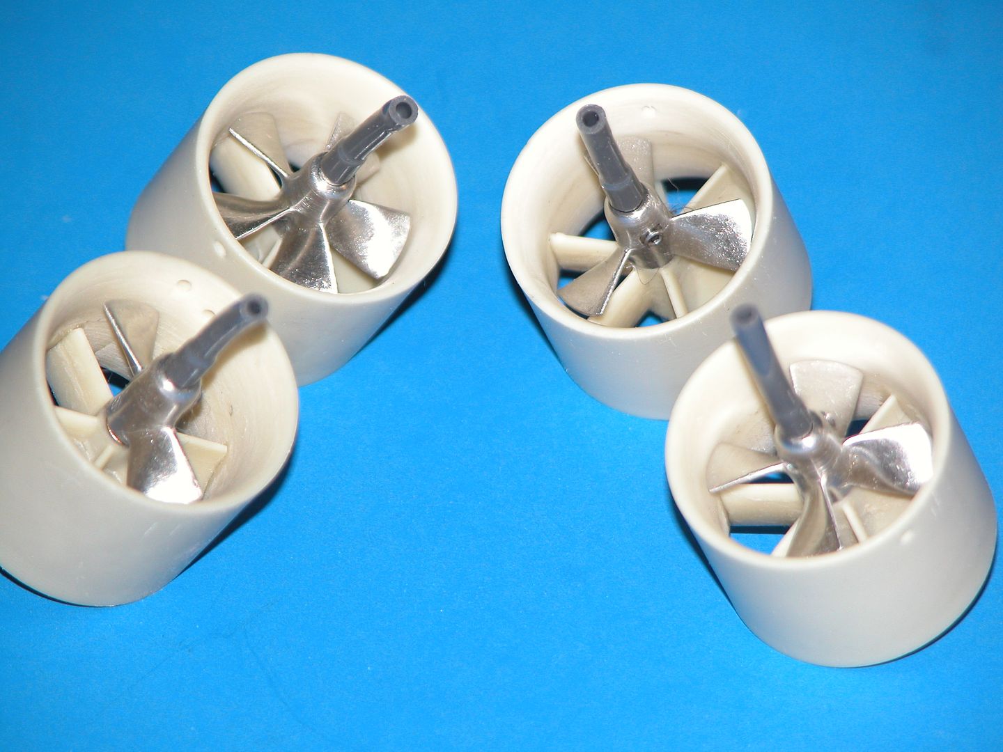
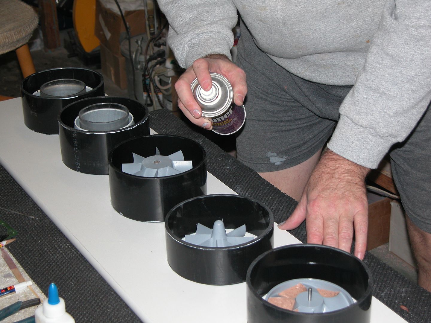
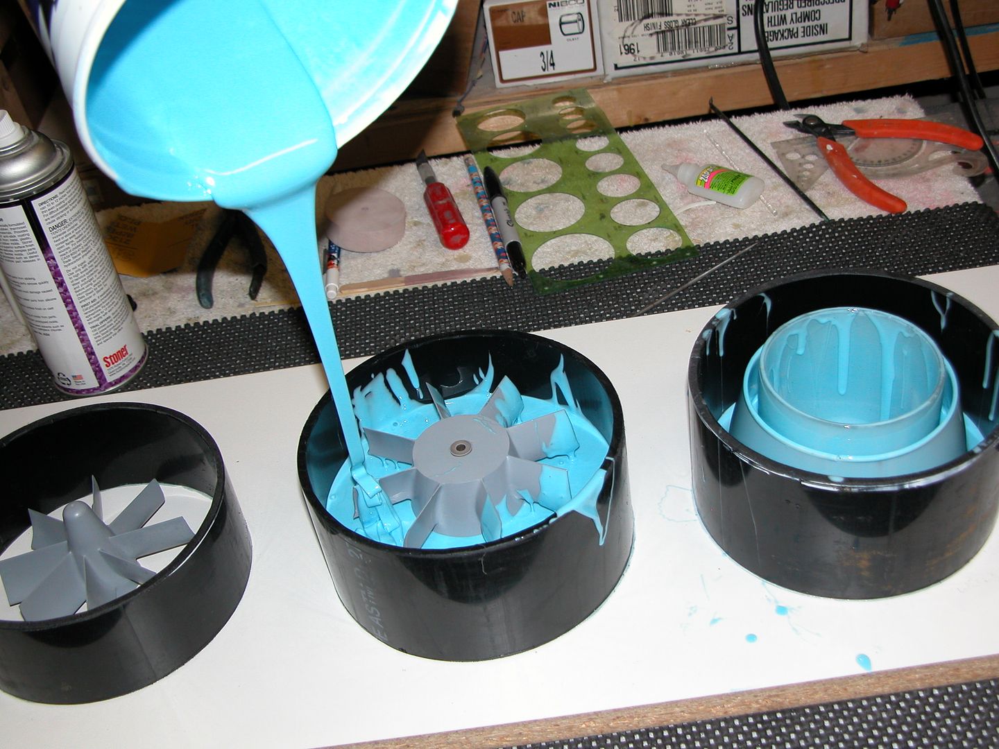
It looks like the former (but never forgotten) Soviets have embraced the British type PJ design. A pre-swirl stator with the rotor aft of that. Makes for easy in-water rotor changes. Here's some shots of the PJ I did for the 1/100 OTW VANGUARD kit:
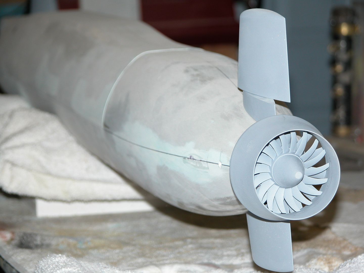
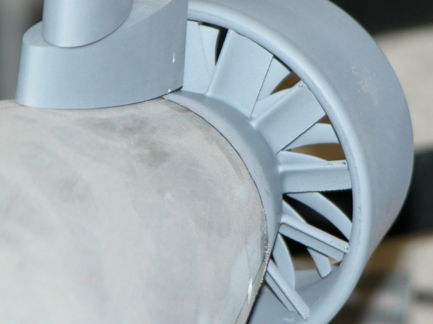
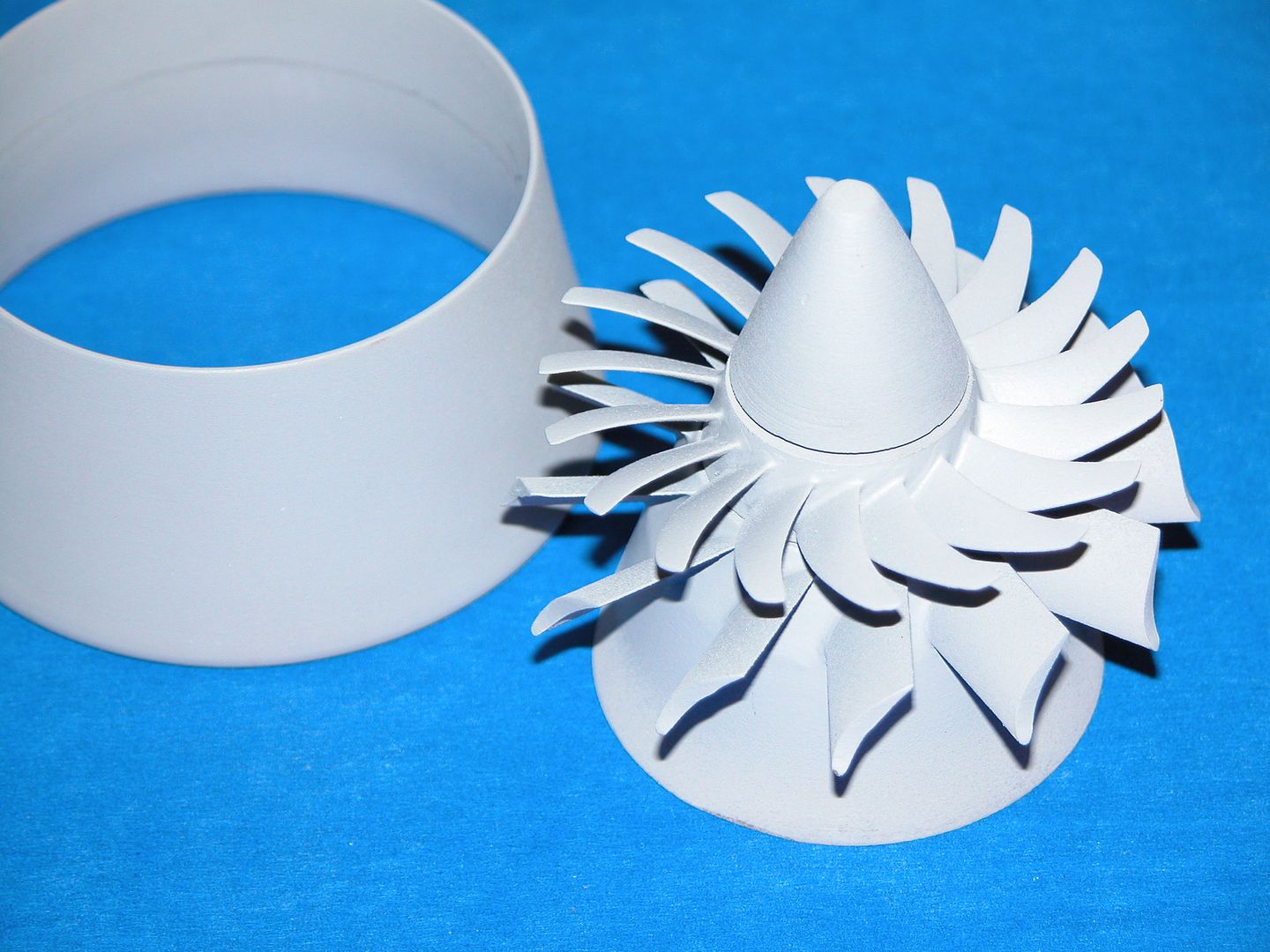
An in-depth look at the many PJ's I've built over the decades is here:

David
Leave a comment:
-
Hey David,
Hope you are feeling better and have a good Christmas.
In the past you have covered pump jet propulsor fabrication in passing when discussing propeller design in general. Could you possibly post some more photos of the differing moulds you create for a pump jet assembly. These intricate shapes look like they will really need me to think though how I will approach this as I head towards fabrication and tooling for Borei's rear end propulsion unit
thanks
David HLeave a comment:
-
I usually vacuum my silicon and use pressure on polyurethane. Unless your polyurethane has a long setup time. There are times when I have vacuumed my silicon with my part in there to get really crisp details. You just have to make sure your part is firmly affixed to the base or sprue.
As far as specs, I called my supplier and asked them. Later I can read you my pumps info when I am done with all the errands for today.Leave a comment:
-
Hi Dave,
I have just bought a Vacuum chamber and have decided upon vacuum de gassing my polyurethane resin before pouring. It is the most pressing issue at them moment for my work. I have been looking at Vacuum pumps on Ebay and the like and so my question to you is,
What are the specifications/vital statistics/numbers, I should be looking for in a Vacuum pump for degassing urethane resin?
thanks,
David HLeave a comment:
-
The trick is to produce a very rough surface to the glove (rubber) element before laying up the hard-shell (mother-mold) over it. The rough texture between mother-mold and glove-mold producing a keying system that keeps the two properly registered during the glass lay-up operation. No creep to ruin the symmetry of the GRP part produced in the tool.
MLast edited by He Who Shall Not Be Named; 04-30-2016, 10:31 AM.Leave a comment:
-
O.K David,
I have some more questions for you regarding production matters. As you know I have developed my boats using the silicon hardback mould method and have found that the detail is absolutely fantastic. It is great to be able to peel the mould off the finished hull part. But therein lies the question, 'finished' I have made numerous copies of the Mike and I have found that they don't come out of the mould perfect. I didn't expect them to, but I am finding that I am having to spend quite a lot of extra time afterwards just bringing them up to a consistency that makes them acceptable.
So how much time to you have to spend on a hull, post moulding? I am not just talking about removing flashing and sanding to the middle/ equator line. Have you got the hull moulding process so down pat that it's limited extra work, remove flashing and the odd bit of sanding here of there or is it more involved for you?
I have found with the silicon mould that although the hardback keeps the silicon mould in shape I have noticed that there can be undulations in the silicon mould wall along the side of the hull. Is this simply because the silicon mould may not be thick enough? I press the sides of the mould up against the hardback shell but sometimes it slightly pulls away and if not checked this could lead to the side of the hull not being an absolutely straight line. Subtle undulations creep into the finished product and so I've had to spend quite a bit of time with the filler and sandpaper to get a smooth consistent surface. I hope that make sense...
I love producing these kits, they are very basic and require initiative to build however I am finding that the hours I'm putting into finishing each hull for sale, I'm glad this ain't my full time job. I would love to get my tooling to the point where the minimum of post production work was required. Is this an illusion or is this how you operate? just curious..
David H
Leave a comment:
-
That's just what you do, David: you provide the stern plane master with about 1/2" of operating shaft extending from each end into the backing clay and make your two-part tool off of that. And when you use the tool for casting you insert a core (another length of operating shaft) into the tool and cast away. You yank the core out of the cast part and that leaves you the desired bore through the piece.
Leave a comment:
-
Here's a question David,
I looked at your write up on pouring the moulds for the whole range of new kits you have acquired. ( save up your pennies). I will be looking at pouring silicon moulds for the Mikes rear surfaces and am deliberating over how to do the rear horizontal planes.
They will have a brass rod that fits through and protrudes out both ends, however the rear fixed plane that it attaches into is "bracketed" at either end. There is no way that I can fit the movable surface in between the two ends of the fixed plane. I will have to align up the movable surface inside the fixed plane then slide the brass rod through the inner end , through the movable surface then into the far end of the fixed plane.
Do you mould the movable plane with a hole through the middle? How do you go about creating the moulds for this? Can you picture the set up I am describing?
I was thinking about pouring the silicon around the movable plane with the brass rod in place. Then when I actually make a part , insert a brass rod coated in Vaseline or some other release agent and then pouring the resin around it. Pull the resin part out and slide out the brass rod.
Thanks,
Dave hLeave a comment:


Leave a comment: