Fitting Everything Into Your SubDriver

Collapse
X
 
  • Time
  • Show
Clear All
new posts
  • QuarterMaster
    Rear Admiral
    • Sep 2015
    • 1194

    #16
    Originally posted by trout
    With these tools I was able to cut the servo to the proper length and add a new end on it. No soldering.....which is a good thing for me.
    Click image for larger version  Name:	002.jpg Views:	1 Size:	30.7 KB ID:	131228


    I shorten and lengthen ALL my Servo leads, and any <=20AWG wire. JUST so easy.

    Even works for single wires, male-female-shrink wrap....done.

    Tools
    Hansen Hobbies Connector Kits

    Connectors and pins
    Hansen Hobbies Miscellaneous Connectors


    I buy 'em in 100 piece lots.

    Cap'n Martin..ADD them to your product line!!

    BECAUSE I'd rather purchase here and keep YOU around!
    Last edited by QuarterMaster; 03-21-2019, 12:09 AM.
    v/r "Sub" Ed

    Silent Service "Cold War" Veteran (The good years!)
    NEVER underestimate the power of a Sailor who served aboard a submarine.
    USS ULYSSES S GRANT-USS SHARK-USS NAUTILUS-USS KEY WEST-USS BLUEBACK-USS PATRICK HENRY-K432-U25-SSRN SEAVIEW-PROTEUS-NAUTILUS

    Comment

    • gantu
      Commander
      • Apr 2009
      • 360

      #17
      Regards Gantu

      Comment

      • Bob Gato
        Captain
        • Feb 2019
        • 826

        #18
        I am sure that this is old news but just in case-These are extremely cheap and cut easily with a razor saw. They're meant for pc boards and the pins are the same as used in RC. I cut into threes -solder a wire to the long lead and the servo connector slips on the pins-They're great for going thru bulkheads..

        Comment

        • Bob Gato
          Captain
          • Feb 2019
          • 826

          #19
          These were 20 pcs for under $6 and there are many styles...M-M...M-F...M-PCB
          20PCS MALE + Female Header 1x40 2.54mm 40 Pin PCB Through Hole Arduino and Pi - $5.99. SHIPS FROM DALLAS, TX! NO INTERNATIONAL DELAYS! Features: Arduino, Raspberry Pi, Pine64, and Breadboard compatible Pin Layout: 1x40 - 1 Row, 40 Pins Pin Pitch: 2.54mm/0.1"; Total Size: 101 x 11 x 2mm / 4" x 0.4" x 0.07"( L*H*W) Easily cut/snap to create the perfect length for your project from 1 to 40 pins Description: These beautiful female PCB headers feature elegant gold plated pins for maximum electrical connectivity. Featuring standardized 2.54mm spacing, they are perfect for use in 223054186518
          Last edited by Bob Gato; 03-24-2019, 07:01 AM.

          Comment

          • He Who Shall Not Be Named
            Moderator
            • Aug 2008
            • 12253

            #20
            Tom, you've sold me on making the investment to swage on new pins. What's the source of supply for the crimping tool and pin blanks?

            And, Bob, thanks for the steer towards the J-type connectors. Good stuff.

            David
            Who is John Galt?

            Comment

            • trout
              Admiral
              • Jul 2011
              • 3545

              #21
              David,
              I got mine at Pololu.com. There are two models,


              Under resources tab they have a short video and photos tab on correct crimps.

              The pins can be ordered here too

              However, you can source these on eBay as well.
              Peace,
              tom
              If you can cut, drill, saw, hit things and swear a lot, you're well on the way to building a working model sub.

              Comment

              • Subculture
                Admiral
                • Feb 2009
                • 2119

                #22
                eBay https://www.ebay.co.uk/itm/SN-28B-Pi...item2a8a99bf6a

                Comment

                • Albion
                  Captain
                  • Dec 2008
                  • 651

                  #23
                  Battery power of SubDriver, is 7.4v sufficient, or am I better off with 3 x 18650 11.1v?
                  Next time someone points out it takes 42 muscles to frown, point out it will only take 4 muscles to b1tch slap them if they tell you how mnay muscles you need to smile:pop

                  Comment

                  • Subculture
                    Admiral
                    • Feb 2009
                    • 2119

                    #24
                    If your motors are designed for 7.4 votls ( or thereabouts), then that's what your should stick with. if you want more running time, consider some higher capacity cells.

                    Increasing system voltage can be worthwhile if the current draw is significant, and beyond what the batteries can reliably handle. This is rarely a problem with a scale models.

                    I do know one chap over on the Facebook Dive-in page who'll give you an argument on that one, and list his qualifications to reinforce his point.l His logic was to run a higher voltage than what the motors are designed for, but to dial down the ESC to run at half throttle. I consider that like shoehorning a V8 into a mini, but never running it beyond second gear, you can do it, but it doesn't make much sense.

                    Comment

                    • trout
                      Admiral
                      • Jul 2011
                      • 3545

                      #25
                      David can correct me on this (and I hope he shares hi thoughts), but I believe the motors can handle the 11.1v just fine. The pump can work with a resistor (may already be installed) at 11.1v. I will not debate the merits of going one way or the other because I am not an expert. Going 11.1v will not necessarily get you more running time, but it does add more juice to the motors. As Andy pointed out, we usually throttle back our ESC anyways, so is there a need to bump it up? I cannot say. For you, build it with the 7.4v, get it running well and then explore 11.1v. if you so desire. My gato with dual motors it was, I think a good decision to go 11.1v, I have a Type VII that is running on 7.4v once I have it working, I will let you know my thoughts.
                      If you can cut, drill, saw, hit things and swear a lot, you're well on the way to building a working model sub.

                      Comment

                      • RCSubGuy
                        Welcome to my underwater realm!
                        • Aug 2009
                        • 1768

                        #26
                        Dave can correct me if I'm wrong, but all the SubDrivers are set up for 11.1V with the exception of the 2" units like the 212, the Type VII, etc. The air pumps are designed for 5 to 8V, so they Dave puts a resistor inline to drop the voltage down for them.

                        Comment

                        • He Who Shall Not Be Named
                          Moderator
                          • Aug 2008
                          • 12253

                          #27
                          Originally posted by trout
                          David can correct me on this (and I hope he shares hi thoughts), but I believe the motors can handle the 11.1v just fine. The pump can work with a resistor (may already be installed) at 11.1v. I will not debate the merits of going one way or the other because I am not an expert. Going 11.1v will not necessarily get you more running time, but it does add more juice to the motors. As Andy pointed out, we usually throttle back our ESC anyways, so is there a need to bump it up? I cannot say. For you, build it with the 7.4v, get it running well and then explore 11.1v. if you so desire. My gato with dual motors it was, I think a good decision to go 11.1v, I have a Type VII that is running on 7.4v once I have it working, I will let you know my thoughts.
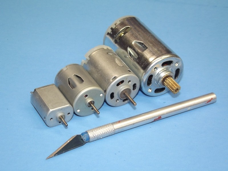
                          It's wise to run a motor at the recommended voltage, as stated by the manufacturer.


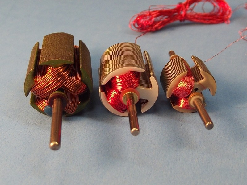
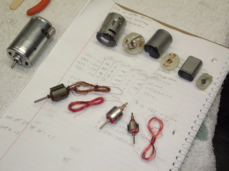
                          Each type motor is wound with the gauge size and number of turns best suited to delivering the optimum magnetic field for the armature geometry (number of poles), at the given voltage.


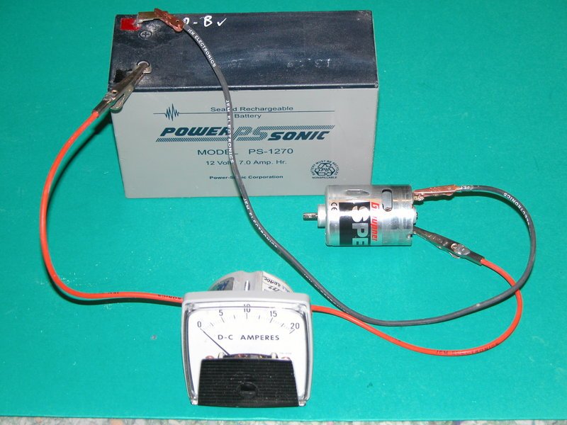
                          The only variable being the current drawn. The amount of Amperage the motor sucks down is proportionate to the load presented to the armature shaft. As an aside: to reduce current load, in some of our SD's, the propeller torque is reduced at the motor by a reduction gear train -- I typically over-speed the motor by a ratio of 3:1 in those cases. This works to speed-match the slow turning propeller to the fast turning electric motor.


                          Operating the motor at any great variance of the recommended voltage results in poor torque or over heating. If the motor is sold as a 6-volt unit, don't exceed 7.4-volts! If the motor is rated for 12-volts, don't exceed 11.1-volts! Notice the variance between stated motor voltage and the voltage I listed -- the very slight variance owing to the switch over from old to new battery chemistry-- not enough of a variance to make much difference here.

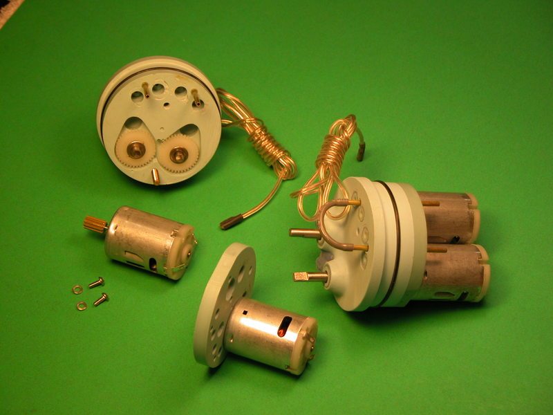
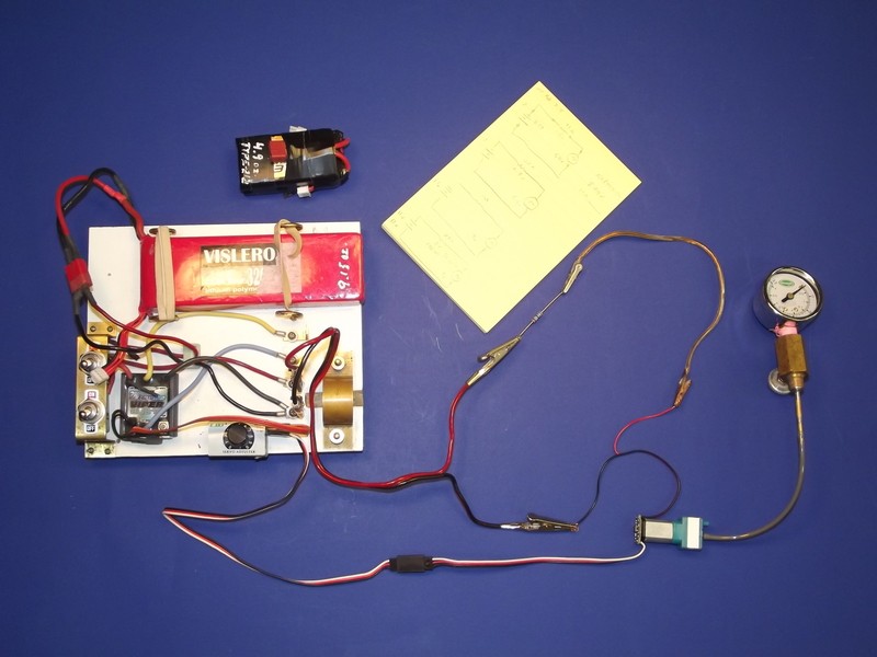
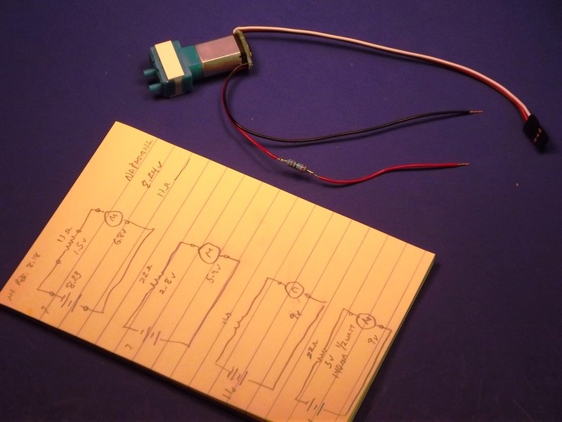
                          As to the low pressure blower (LPB) motors: The larger one is rated at 12-volts, and this unit is only used within the 3.5 SD's where the power bus is 12/11.1-volts. However, the 2, 2.5, and 3 SD's employ a smaller LPB whose motor is rated for 6-volts. Only the 2 SD's employ a 7.4-volt power bus, so those LPB's work fine off the line. However the 2.5 and 3 SD's make use of a 12/11.1-volt power bus so those little LPB motors have a voltage dropping resister in series with the motor to insure that the motor only sees 5-volts or so.


                          Ohm's Law is your friend!

                          David
                          Who is John Galt?

                          Comment

                          • Bob Gato
                            Captain
                            • Feb 2019
                            • 826

                            #28
                            Thanks David -well said-well illustrated...for us lazy guys who don't like math this calculator might help
                            Trying to run something at a different voltage then you can try a simple resistor to do the job. The Dropping resistor calculator works for things like running LED's from different voltages. Simple example provided with the calculator.

                            Comment

                            Working...