Thanks David!
I will get this 212 built and in the water, one way or another for sure!
Rob
"Firemen can stand the heat."
-
Work with what you've got, Rob. Keep slugging tough guy! Ya got back-stops here if you need 'em. Just call out.
DavidLeave a comment:
-
Well after attempt and attempt, I am going back to my original design.
My poor eyesight just won't let me work like I used to. And without elaborating I am going to work on the original method.
This is the same design and method that Bob Martin (Nautilus Drydocks) uses on his new 212 A kits.
Nautilus Drydocks 1:72 German Type 212 Instructions CH2 (youtube.com)
The video above shows the installation process that I will be using.
Rob
"Firemen can stand the heat."Leave a comment:
-
I am hooked and ready to go!!
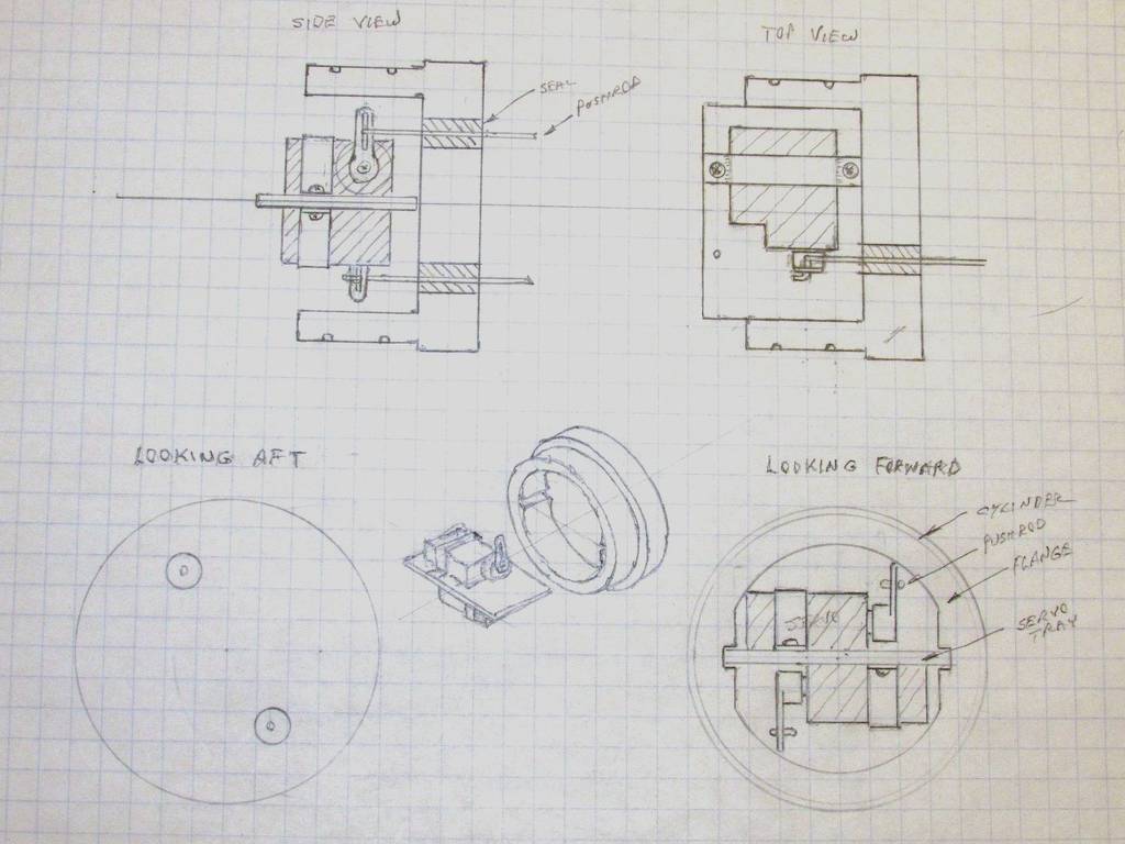
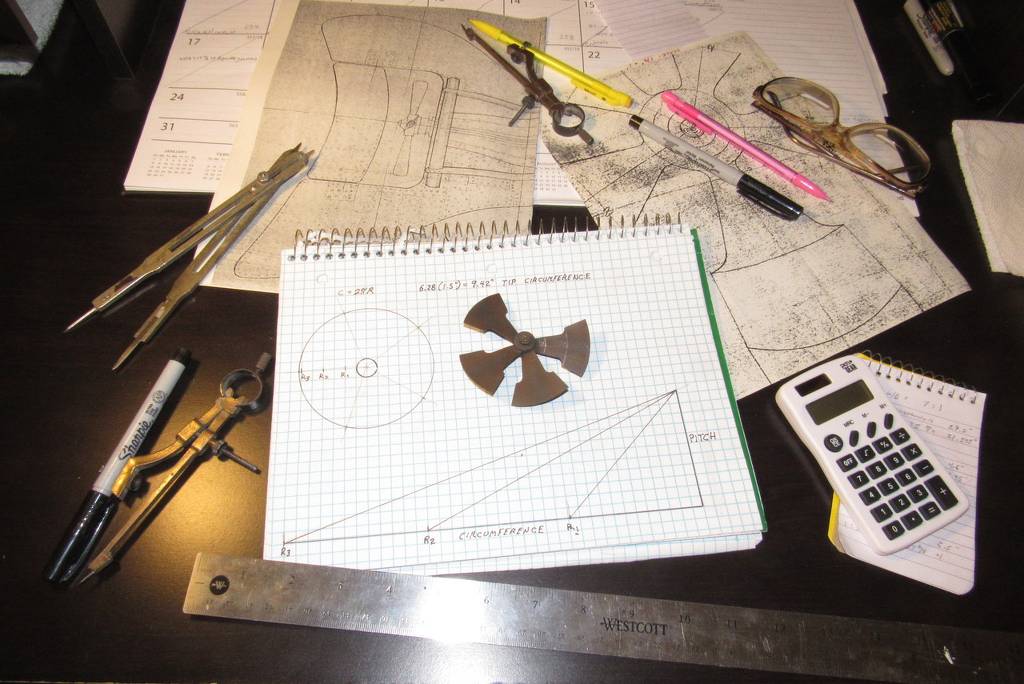
David M's influence strikes again! " It's hard to know which road to take without a map" I can now see that a SCALE drawing of the interior stern section will allow me to design a yoke
(to scale) that will make fabricating and installing it much easier.
I realize a lot of you will laugh somewhat at me putting up my drafting table, and that is fine, but I now understand how prior design and planning can make the overall fabrication go much better in our submarine building... And to that end, we build on!
Rob
"Firemen can stand the heat."Leave a comment:
-
Tom,
I have got to agree 100% with what you have stated. And I do appreciate all the input I am receiving. David is such a master at what he dose. I so respect his methods of achieving.his end results. His engineering drawings, methods of fabrication, set up, final detail finish work, and then the final masterpiece. What more can I say! Except to thank him for all the advice and help he has given me along the way!!
I do not want to slight many others who have been very helpful to me as well, and that includes you Tom!!
Rob,
"Firemen can stand the heat."Leave a comment:
-
-
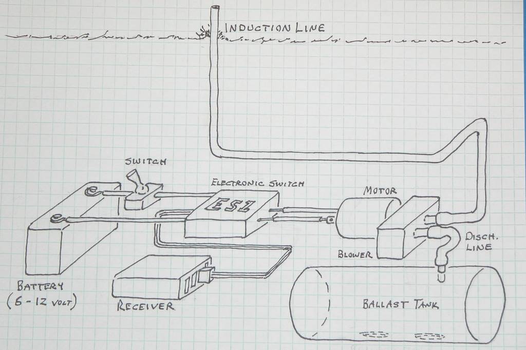
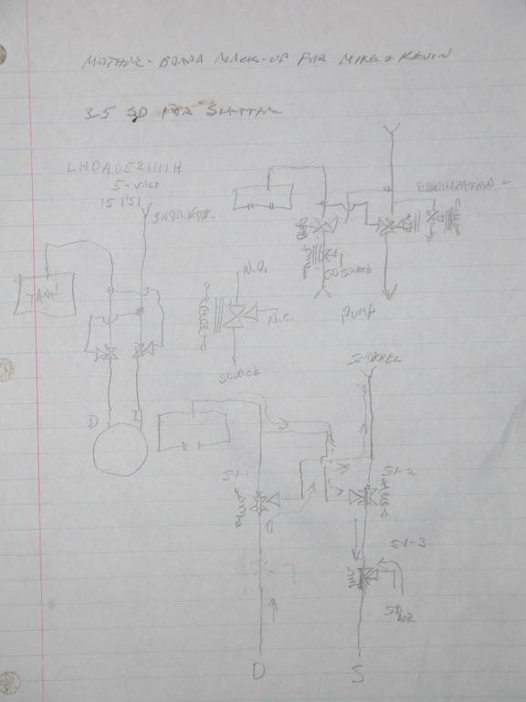
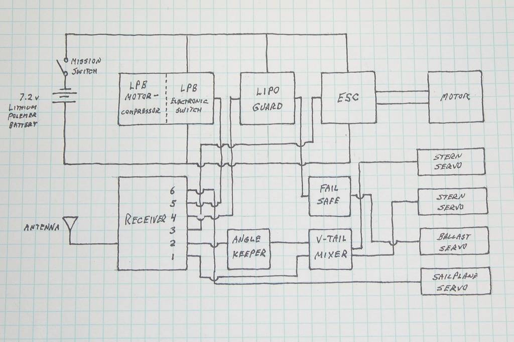
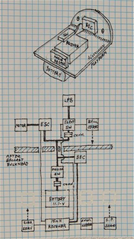
I was just amazed at the information dump in your post. David you hit everything from search for lost sub to electronic schematics. Amazing work. I will be downloading these images.Leave a comment:
-
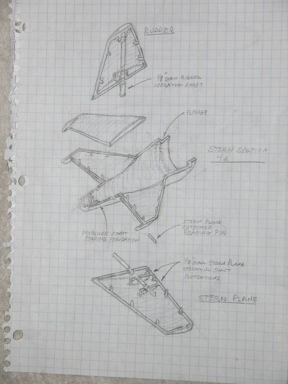
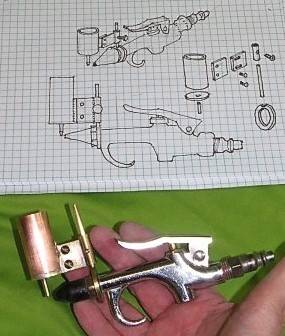
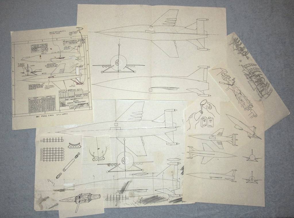
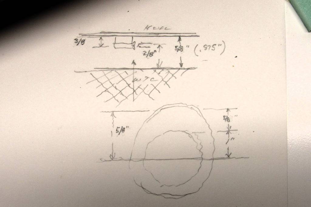
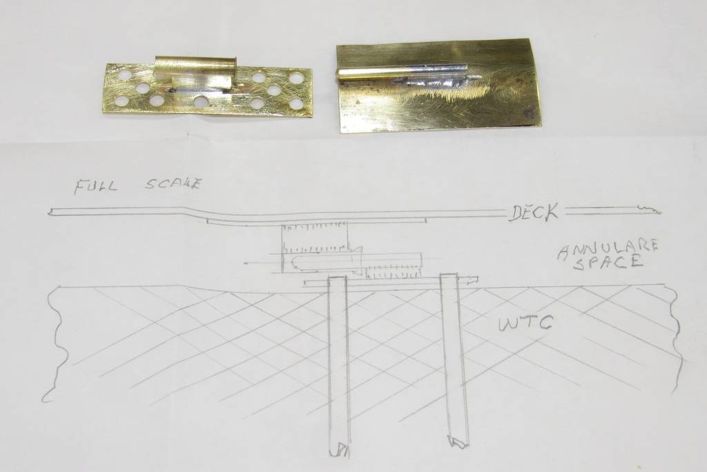
That illustrator provides so much direct and indirect information; all done in two projections of the same item: the plan orthographic permits direct measurements to be lofted to the work (pure layout gold). The bottom perspective projection conveys rough dimensions not suitable for lofting but highlights the three-axis relationship between all items presented. Add a profile orthographic projection to this work and you have everything needed to array the devices presented. Yeah -- I would frame and hang that illustration as well, Ken. Excellent work.
Some of my refined illustrative work has appeared in books, one book jacket, instruction pamphlets, industrial house organs, catalogs, box-art, and numerous magazine articles.
One book, without permission, mistakenly published one of my three-views as source material -- when in fact it was nothing more authoritative than 'fan art'.
DavidLast edited by He Who Shall Not Be Named; 03-22-2024, 10:10 AM.Leave a comment:
-
Some of your artwork David looks good enough to frame and hang on the model submarine builder nerd's office or shop! Love the artwork!
Here's one I have in my office that a friend did.
Leave a comment:
-
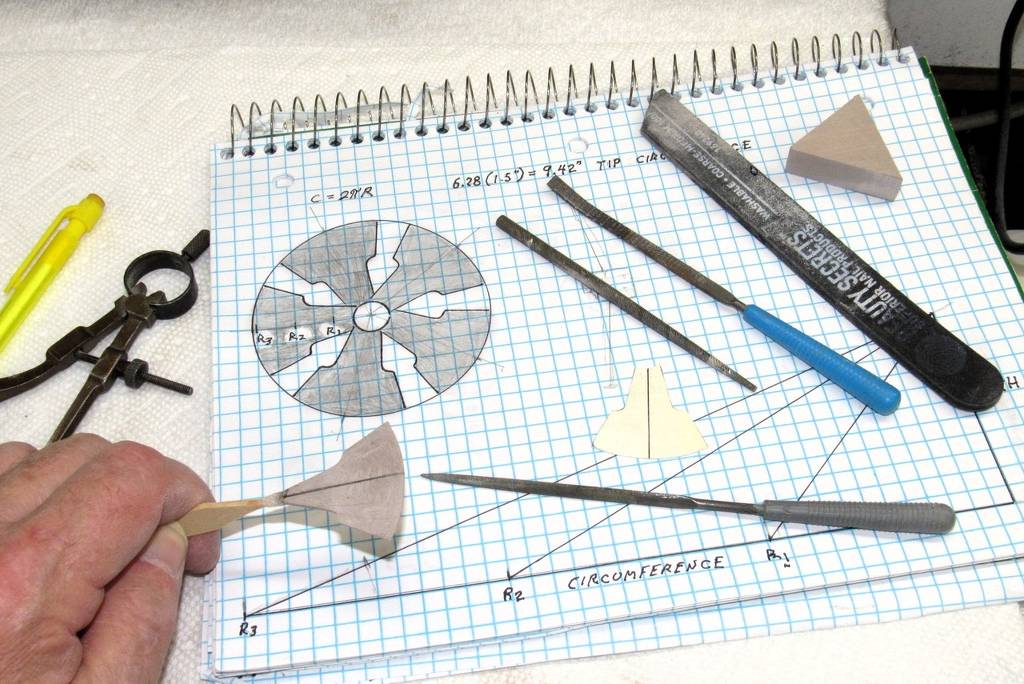
My pleasure, Rob. The layout process, so unappreciated by so many. Hard to pick the correct road without a road-map.


DavidLast edited by He Who Shall Not Be Named; 03-21-2024, 05:51 PM.Leave a comment:
-
David,
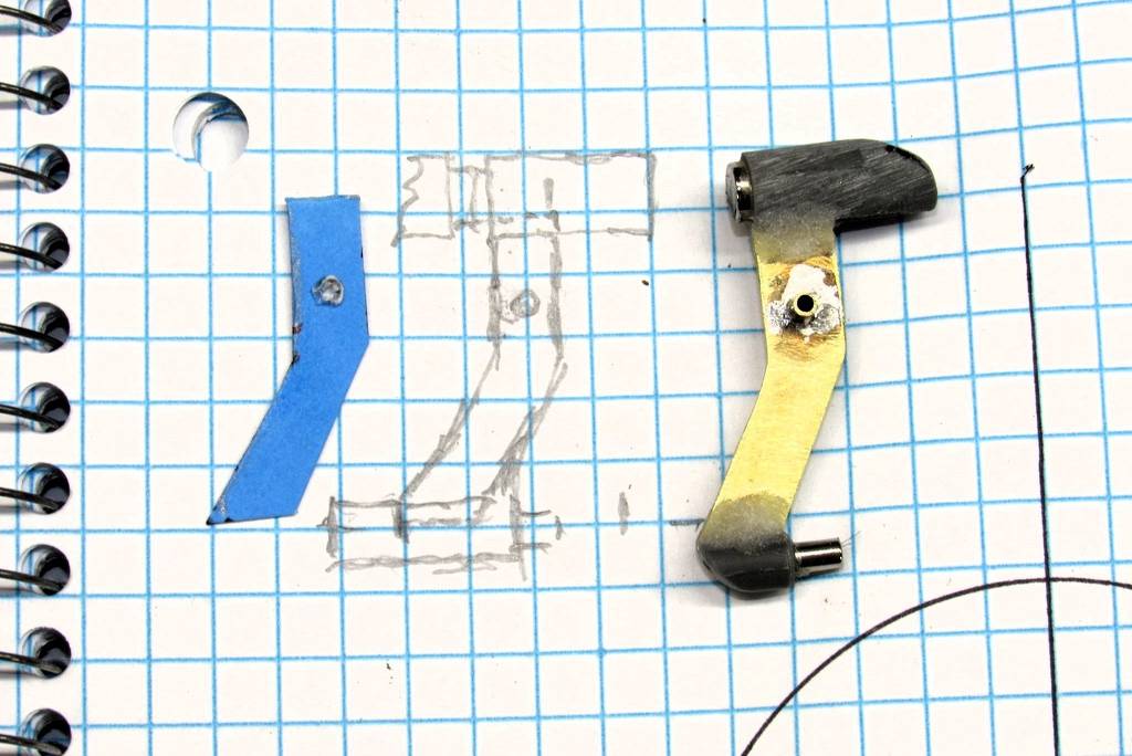
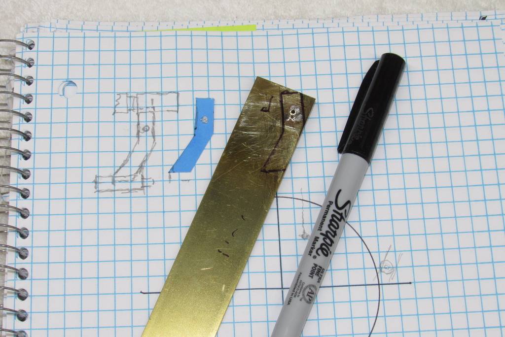
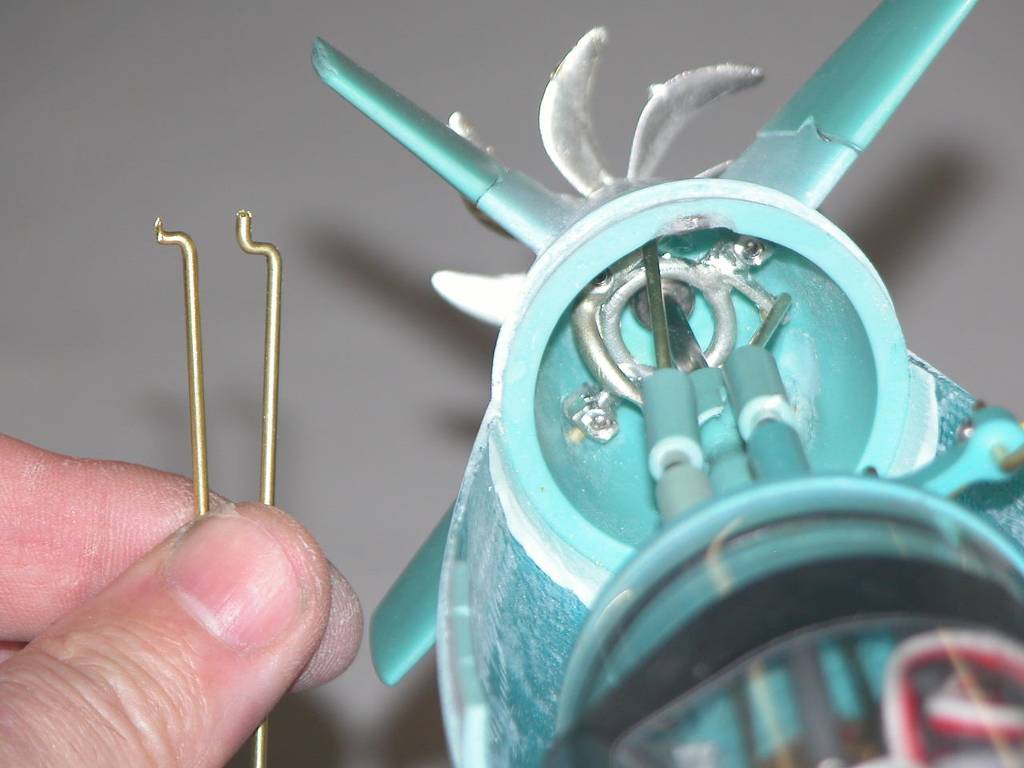
Thank you very much for the great photos and the illustrations. I will be using your brass yoke designs and especially your layout work before your fabrication. I am really starting to appreciate a scale drawing prior to fabrication.
Thank you for your time and expertise ounce again David.
Rob
"Firemen can stand the heat."Leave a comment:
-
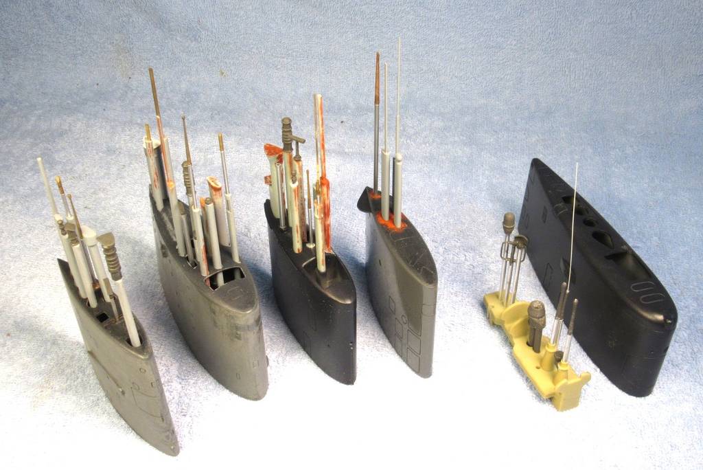
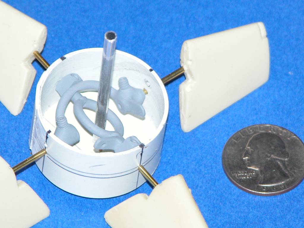
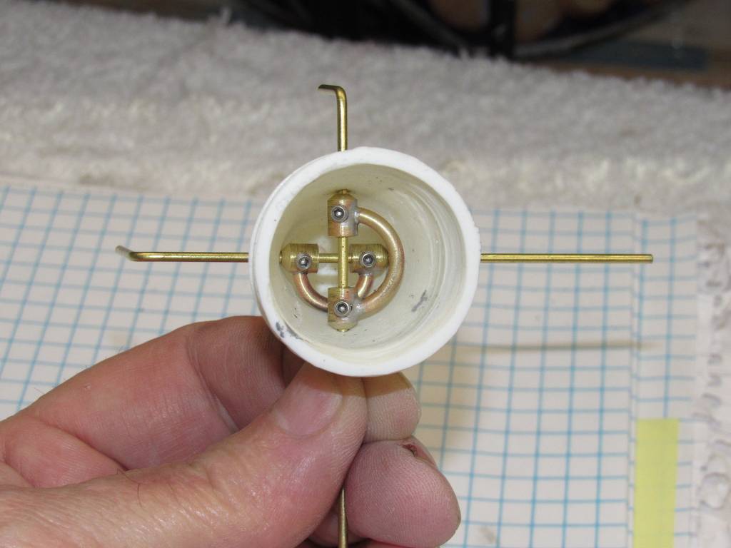
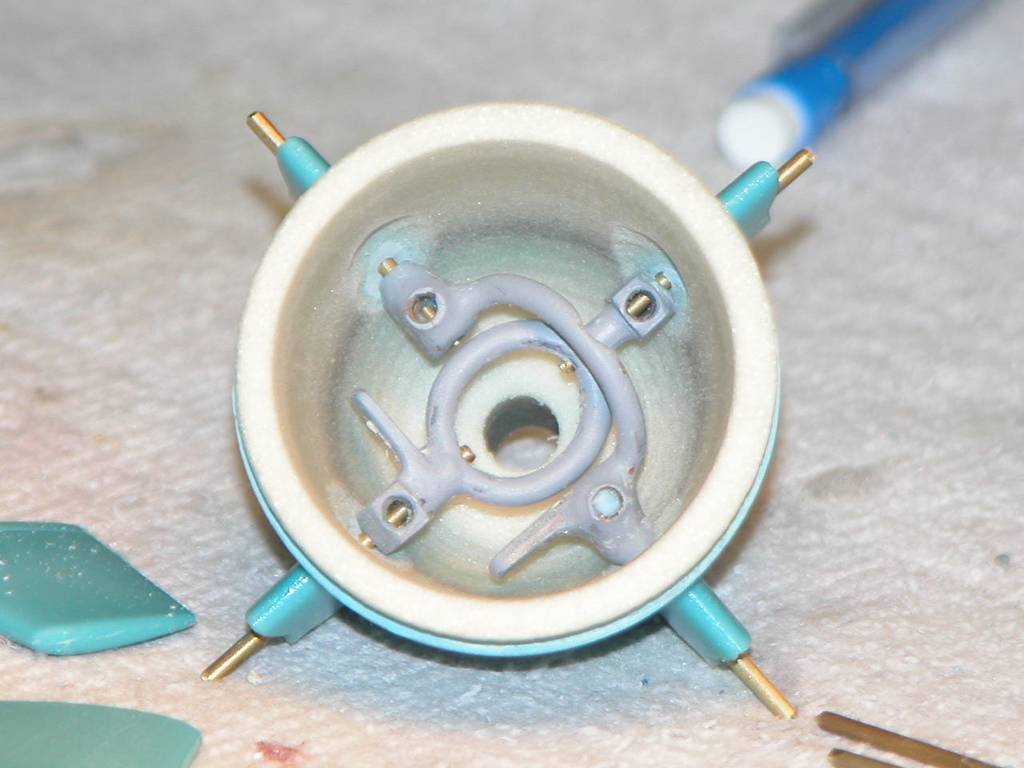
This is what I think will be my solution to solve the stern section interior!
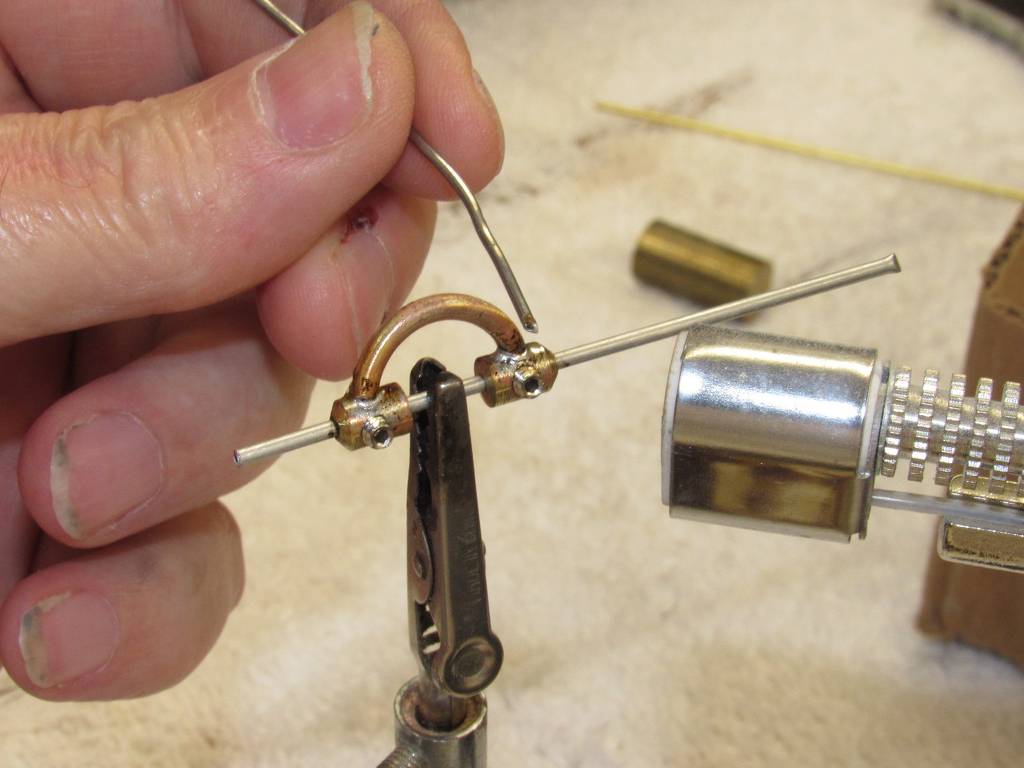
I used Simplify 3D slicer to cut the stern section into two separate pieces. This will give me much better access to the control linkage installation. As stated above, I am going with 1/16" stainless steel rod in place of the brass.
Rob
"Firemen can stand the heat."Attached FilesLeave a comment:
-
-
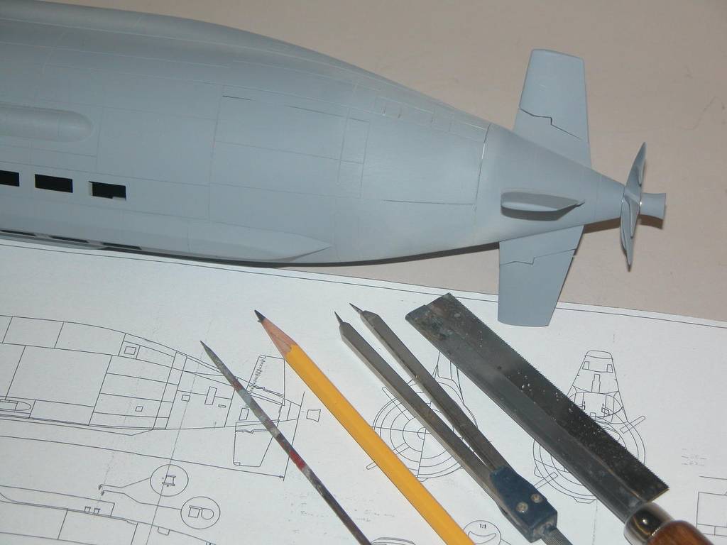
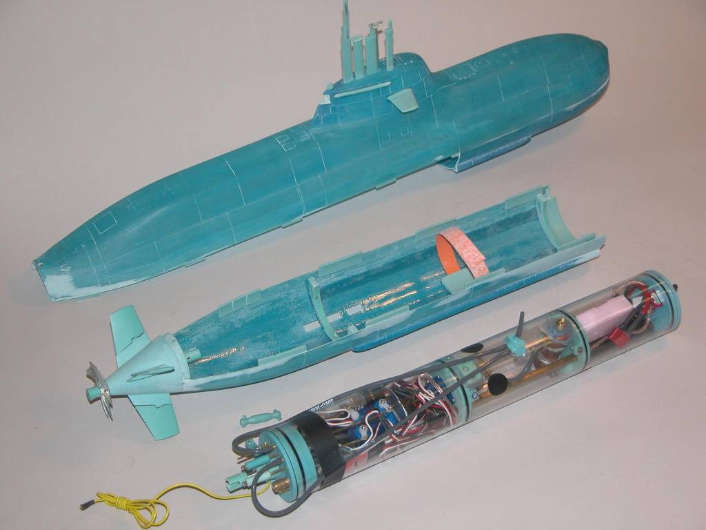
Bruce,
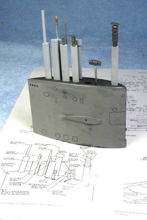
Here are the dimensions of my hull, and at this point about where the cylinder will be located as well.
The overall length is 31"
Measuring from the front of end cap to the bow opening is 6"
Hope this helps you.
Rob
"Firemen can stand the heat."Leave a comment:


Leave a comment: