
INTRODUCTION
Ellie and I registered our business, D&E Miniatures, sometime in the late-70's. We became a proper business at that point and carried on with our work of manufacturing and selling small display and commemorative models to individuals and institutions. That move put us on the map and secured a tax exempt number.
Other than that, becoming a sole proprietary business made little difference to our day to day activities: I was still in the Navy, Ellie was wrangling two Alpha teenagers and worked at Electric Boats 'canteen', and we built models for money on the side.
Time had come to step up the business, so we chummed the waters. A brochure listing our services was prepared and hundreds of them were mailed out -- mostly to big industrial players, movie studios (though the studio system was crumbling then, I reasoned that there might still be some meat on those bones), schools of Engineering (those with tow tanks and/or wind tunnels), a few shipyards, NASCAR sponsors, airlines, and cruise lines. In those days, before the Internet, the connective tissue between businesses was the big, green Thomas Register books. Within those pages we found our target audience.
And, damned if that didn't work!
In no time we began to be wooed by members of the defense industry. Models to be displayed at the many trade shows such businesses attended domestically and abroad. We soon found that working for people who promoted and fostered, 'man's greatest outdoor activity' was good money. No big surprise to me, but a bit of a culture-shock for Ellie to learn that those who make, promote, and sell weapons of war, and their vendors, make a good living.
One of my duty-stations was the dive-locker aboard the destroyer tender, USS VULCAN. I spent my entire four years working the ships tied up at the Naval Base, Norfolk. No underway time, no duty-section; a regular day-time job. And those four years I worked at the south end of the base, in a double-wide tailor with the other VULCAN divers. I pulling down base-pay, dive-pay, and sea-pay! During the day a ships husbandry diver; by night and weekends, back at home, Ellie and I were busy building models for The Lords of War. Life was good!
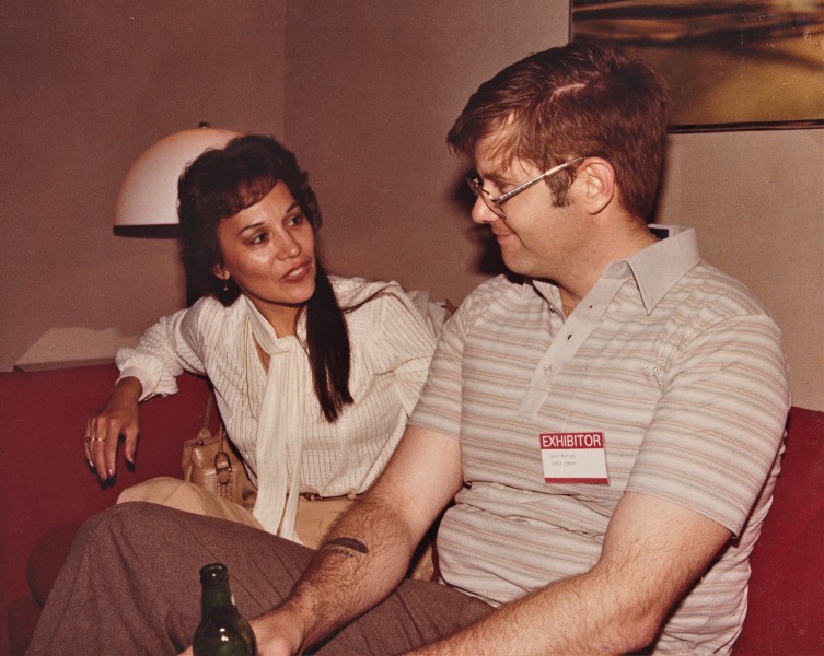
We built a lot of 'interesting' models for the defense trade. On occasion a client would put the two of us up at the convention site to baby-sit the display pieces; to be on hand if the models needed moving or repair. Someone snapped this shot of us at one of the D.C. Navy League sponsored defense conventions as we took a breather in the clients 'hospitality suite'.
Typically, the division of labor went like this: Ellie did the production work and screened inquiries. I did the research, layout, masters, tools, and detail stuff. That put the RASHER job firmly in my court.
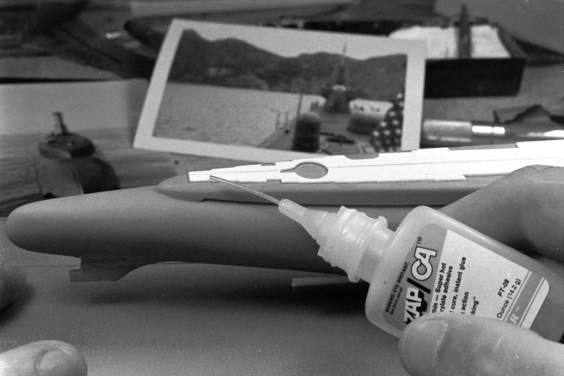
But, though we were kept busy with the defense clients, I did accept the occasion commission from private individuals. Which was the case with the subject presented here: a 1/180 scale, highly detailed model of the USS RASHER, SSR 269. The client sent me a stack of photos and his suggestion that I work up the display using the then available Revell LIONFISH plastic model kit.
The RASHER and her sisters were WW-2 era GATO class diesel boats modified to serve as radar picket submarine -- advance scouts for fleet battle groups. Hence the new designation SSR. The Migraine-3 program defined and oversaw the modification. The Migraine-3 boats, of which the RASHER was a member, were extensively reworked. They were lengthened, their stern tubes removed to make room for the increased compliment, huge air-search radars installed atop their GUPPY like sails, and a dedicated air-control center installed to coordinate friendly air operations as well as presenting the tactical situation to the battle-group Commander. But, the days of the SSR's were brief as AWAC aircraft, satellites, and SSN's quickly took over the roll of battle-group point-man.
DBF.

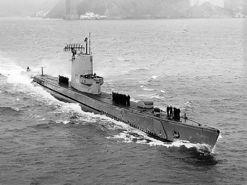
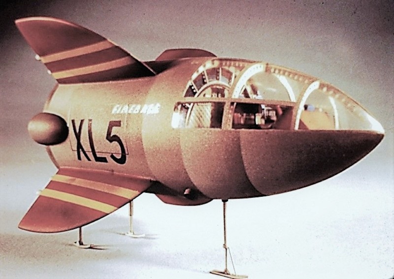
This picture of RASHER shows her a short time after the Migraine-3 conversion, as the bulbous height-finding radar just abaft the sail and smaller 'homing beacon' radar near the turtle-back are still in place. These items were soon removed leaving only the big sail mounted BPS-2 radar antenna to tell the world that RASHER was a radar picket submarine.
The projecting bridge 'wings' permitted the conning officer and lookouts to get a view aft without their line of sight being to badly blocked by the elongated sail.

(My apologies for the grainy quality of the following in-work and beauty shots that chronicle creation of the RASHER display. I documented this work in the late 80's, before I embraced digital photography. The pictures that follow were recently copied digitally from the original, and slightly time diminished, color slide positive film and black & white negative film I've retained through the years).


Three major tasks presented themselves as I converted the LIONFISH kit to the Migraine-3 RASHER: Lengthen the hull and capture the 'knuckle' where the forward end of the hull extension piece butted up ugly to the rest of the submarines bow; manufacture of an entirely new sail fairwater with its weird bridge wings; and creation of that big BPS-2 drag inducing parachute of a radar antenna mounted atop that sail.
THE HULL
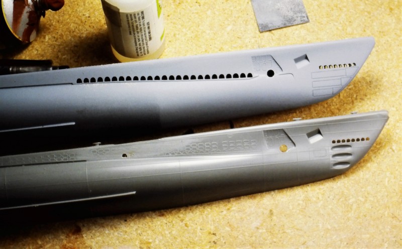
The Migraine-3 boats were lengthened to make room for the CIC space and additional equipment.
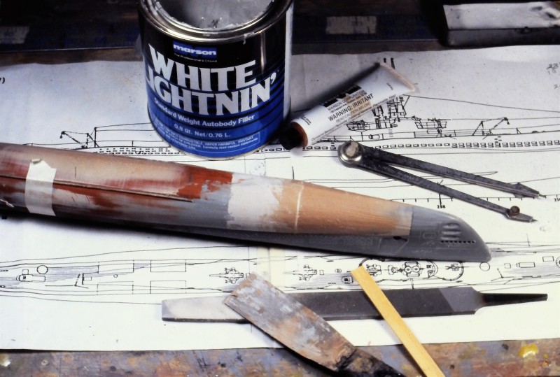
To extend the kits hull 25-scale-feet I bought a second LIONFISH kit and grafted a portion of that to the display hull. The graft done at the hulls maximum breadth so as not to spoil the natural curve of the hull. Once the hull was lengthened I would later ugly up the hull at the point near the bow where the hull extension was performed on the actual boat.

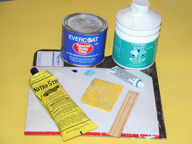
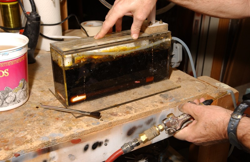
Automotive filler -- classified as a thermosetting type plastic -- is a mixture of polyester resin and finally ground, inert 'filler' to thicken the product. The catalyzed goo can be applied, in mass, to a surface in need of re-contouring without fear of sagging. Unlike air-dry putties (like my favorite, Nitro-Stan) that can't be put on too thickly, with a catalyzed filler the thicker you put it on, the hotter it gets, and the quicker it changes state from semi-liquid to hard mass.
For this discussion I'll use the trade name of a familiar brand of filler: 'Bondo'.
The after end of the extension segment attached at or near the operations compartment forward bulkhead -- a bit forward of the conning tower-fairwater leading edge. This constant diameter extension of the pressure hull, and saddle type ballast tanks that surrounded it, resulted in a nasty looking 'knuckle' at the forward end of the extension. This, of course, ruined the smooth lines of the hull so close to the sharply curving bow. Oh, well... function over beauty, as they say.
I built an external radial frame from .065" thick polystyrene sheet. This external reference frame girdling the hull where the forward end of the hull extension piece was to be. That frame, at its outer edge, having the same geometry as the after end of the supposed extension.
I screeded on catalyzed Bondo to the height of the external frame both fore and aft, feathering the filler to the surface of the hull. With just a few careful passes of a broad bladed putty knife, I had roughed out a credible looking 'knuckle' to the hull lines forward.

Some filing and sanding, a bit more Bondo, more sanding, then Nitro-Stan air-dry touch-up putty to address file and sanding marks, yet more sanding, and the hull was ready for gray primer.
Bondo was also used to fill the concave portions of the bow and stern torpedo tube shutter doors. Also, a bit of Bondo was used to fill the gap between the wooden sail and GRP bridge structure once they were glued together.
A word to the wise: Bondo like fillers are for re-contouring and filling of significant gaps. The Nitro-Stan air-dry lacquer based touch-up putty, on the other hand, is for very shallow gaps and tool-marks.
Don't use hobby-shop sold air-dry putties or paints... they're crap; formulated to be safe, not effective. Green-Stuff and the like, if applied too heavily, will take years to thoroughly harden. Nitro-Stan is much quicker to dry owing to that products extremely volatile solvents.
Hint: If the product labeling does not warn of cancer, warts, lung damage, distemper, Ebola, or your **** falling off, the stuff is useless! The good stuff -- putties, primers, paint, and clear coat systems -- will be found at automotive supply houses and Ebay.
GLASS REINFORCED PLASTIC (GRP)
fiberglass layup is the process of forming tough, light weight, thin walled structures by encapsulating strands of fiberglass with a hardened plastic resin. The resin, once it changes state from liquid to solid, provides the stiffness. The embedded glass strands endows the structure with great strength. Just the right material from which to fabricate the open bridge structure at the leading edge of the sail.
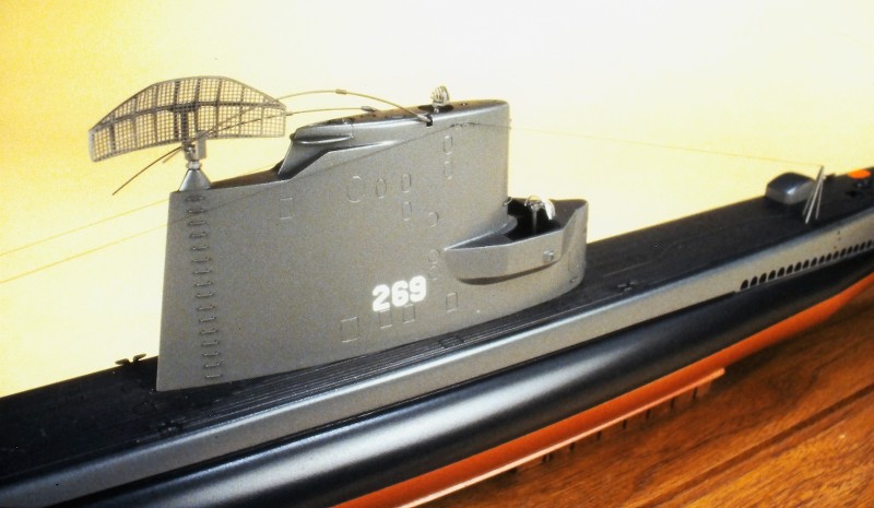
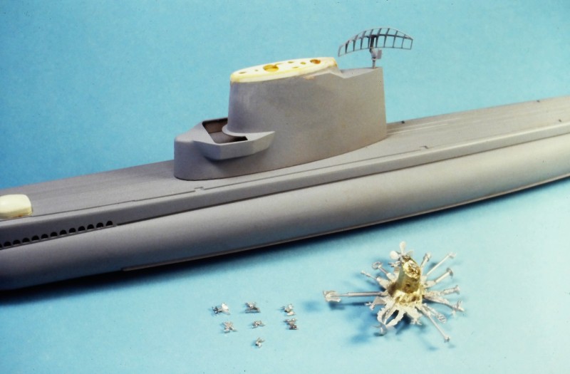
Note the semi-circular clear spray-shield and compass repeater atop and within the open bridge cockpit.
Keep in mind, as you examine this photo, that the entire sail structure is made from three substrates: wood, GRP, and vacuformed polystyrene. Looks like one large organic structure doesn't it? The wonders of filler, putty, sandpaper, plenty of elbow-grease, primer, and paint on display here.
THIS is model building! Not something pooped out from the back-side of a Star Trek Replicator.
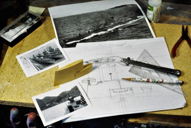
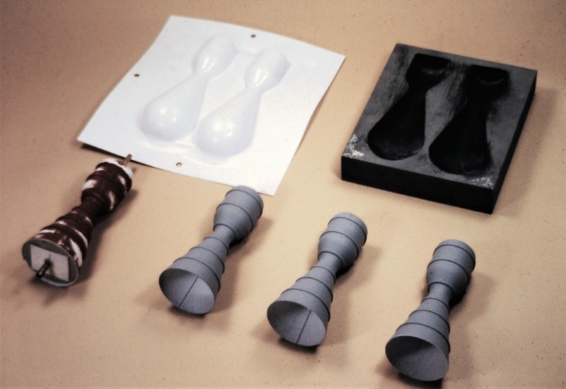
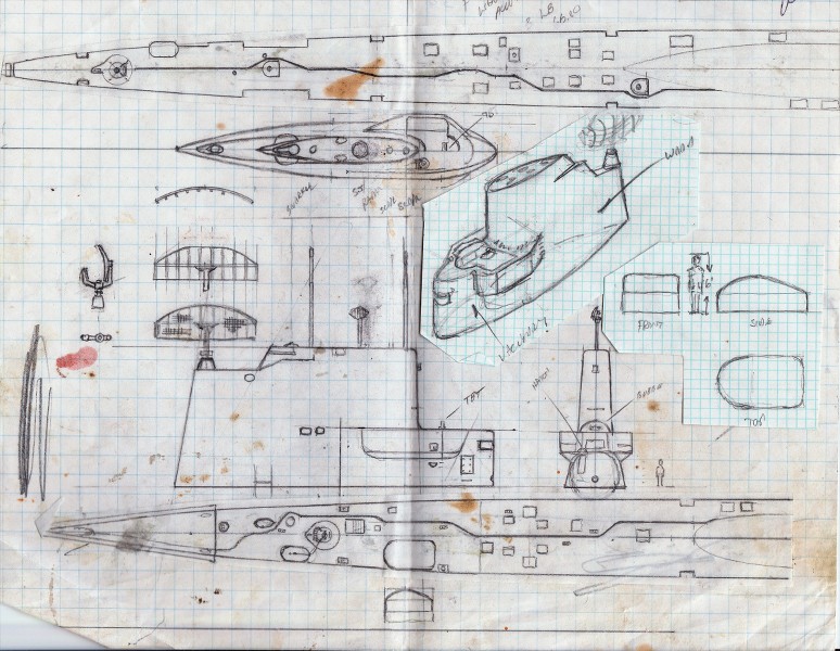
First, I prepared a scale three-view shop sketch of the proposed sail structure. Study of that drawing informed me as to where to employ wood, vacuformed polystyrene, and GRP.
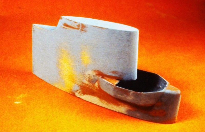
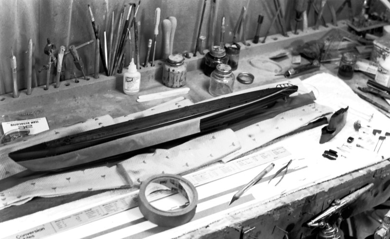
Two slabs of pattern making wood (kiln dried and well seasoned Basswood -- these were the days before RenShape) were epoxied together, after first tinting the glue black. This produced a well defined centerline along the length of this sail blank, no matter how it was sawed, filed and sanded; the master would always present a dark centerline at all edges; that reference plane assuring symmetry between port and starboard halves as I worked the basic sail piece to shape.
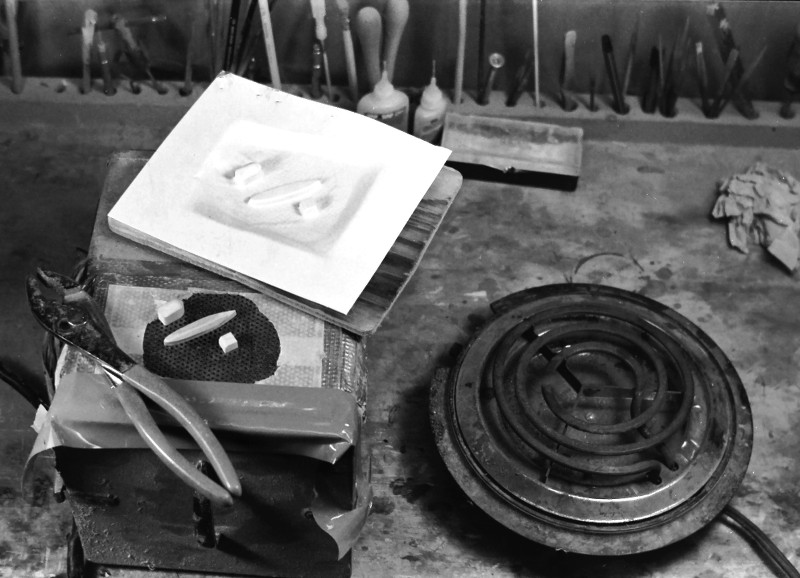
However, before joining the two halves of the sail blank I laid down a square of wax paper between the halves where the eventual bridge structure would be -- I would later remove that portion of the sail and then split it along the glue plane. The wax paper made that task an easy one.
Once the glue had cured hard I razor sawed off the top of the sail -- later using that piece as a pattern for vacuforming. The forward lower corner of the wooden sail was cut away, and a tongue-and-groove indexing system provided to insure exact keying together of the two sub-assemblies.
Working the split bridge master involved extending the bridge cockpit, port and starboard, with more Basswood, those pieces screwed (and later glued) in place to the sides of the bridge master. I periodically assembled the bridge to the sail to insure a smooth transition at their mating points.
You see, to good advantage here, the dark centerline plane left by the darkened epoxy.

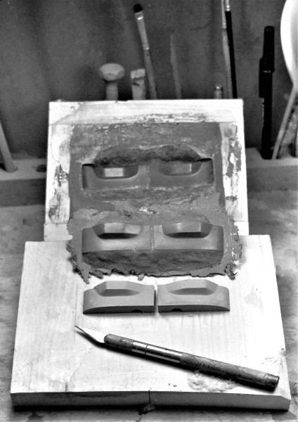
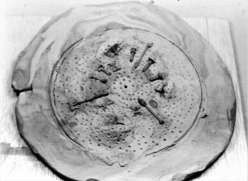
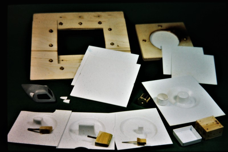
The eventual GRP bridge structure would be laid up within a hard-shell GRP tool (mold). Here I've separated the bridge master into halves and mounted them on a mold board.
The face of the mold board and masters were first waxed then given several coats of polyvinyl alcohol (PVA). These agents producing a barrier -- a mold release -- between masters and GRP used to create the tool, keeping the laidup tool from permanently (and tragically) bonding to the master and mold board.
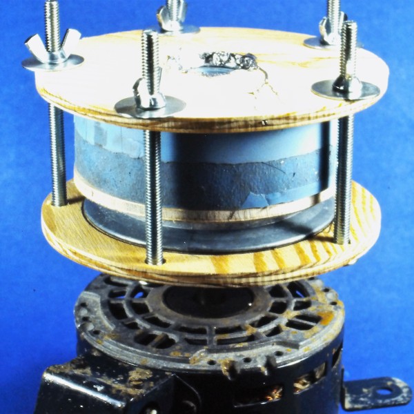
Tool making started with brushing on a well thickened 'gel-coat' of epoxy laminating resin over the patterns and mold board. Once that layer had hardened to a tack-free state I laid on several plys of 10 ounce glass cloth, and saturated the cloth with laminating resin. After a two-day cure I popped the bridge structure tool off the masters and got to work laying up the GRP bridge structure halves.

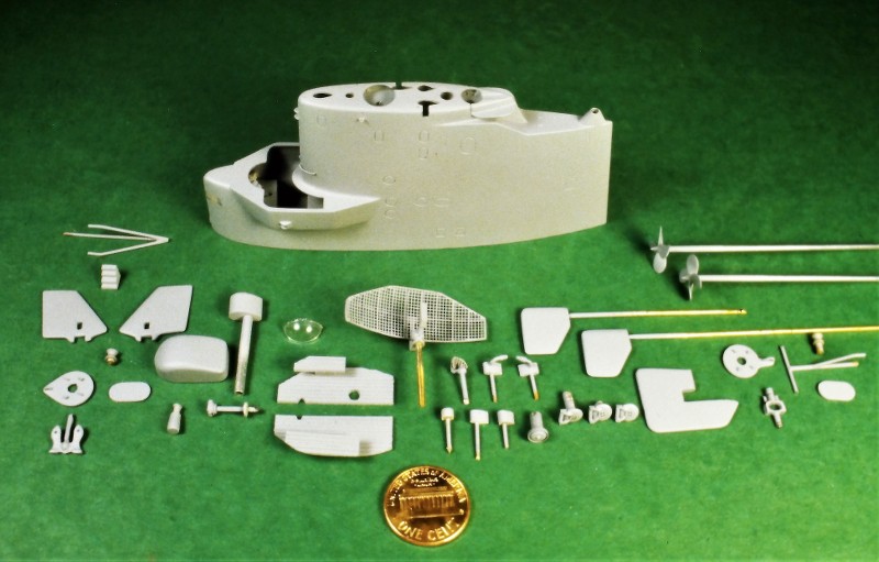
In background is the hard-shell bridge structure tool. Mid-ground is a raw test lay-up as it looked straight out of the tool. And foreground is a trimmed set of bridge structure GRP parts that will eventually be assembled and installed to the leading edge of the wooden sail.
The completed GRP bridge structure about to be bonded to the wooden sail.

Illustrating the use of Bondo filler, Nitro-Stan air-dry putty, CA, and primer -- all employed to attach and fair in the GRP bridge structure to the wooden sail structure. Looks like hell here, but a few squirts of gray primer and it all comes together, seamlessly!
When all the smoke clears, this is the result.
Damn!... I'm good.
Ellie and I registered our business, D&E Miniatures, sometime in the late-70's. We became a proper business at that point and carried on with our work of manufacturing and selling small display and commemorative models to individuals and institutions. That move put us on the map and secured a tax exempt number.
Other than that, becoming a sole proprietary business made little difference to our day to day activities: I was still in the Navy, Ellie was wrangling two Alpha teenagers and worked at Electric Boats 'canteen', and we built models for money on the side.
Time had come to step up the business, so we chummed the waters. A brochure listing our services was prepared and hundreds of them were mailed out -- mostly to big industrial players, movie studios (though the studio system was crumbling then, I reasoned that there might still be some meat on those bones), schools of Engineering (those with tow tanks and/or wind tunnels), a few shipyards, NASCAR sponsors, airlines, and cruise lines. In those days, before the Internet, the connective tissue between businesses was the big, green Thomas Register books. Within those pages we found our target audience.
And, damned if that didn't work!
In no time we began to be wooed by members of the defense industry. Models to be displayed at the many trade shows such businesses attended domestically and abroad. We soon found that working for people who promoted and fostered, 'man's greatest outdoor activity' was good money. No big surprise to me, but a bit of a culture-shock for Ellie to learn that those who make, promote, and sell weapons of war, and their vendors, make a good living.
One of my duty-stations was the dive-locker aboard the destroyer tender, USS VULCAN. I spent my entire four years working the ships tied up at the Naval Base, Norfolk. No underway time, no duty-section; a regular day-time job. And those four years I worked at the south end of the base, in a double-wide tailor with the other VULCAN divers. I pulling down base-pay, dive-pay, and sea-pay! During the day a ships husbandry diver; by night and weekends, back at home, Ellie and I were busy building models for The Lords of War. Life was good!
We built a lot of 'interesting' models for the defense trade. On occasion a client would put the two of us up at the convention site to baby-sit the display pieces; to be on hand if the models needed moving or repair. Someone snapped this shot of us at one of the D.C. Navy League sponsored defense conventions as we took a breather in the clients 'hospitality suite'.
Typically, the division of labor went like this: Ellie did the production work and screened inquiries. I did the research, layout, masters, tools, and detail stuff. That put the RASHER job firmly in my court.
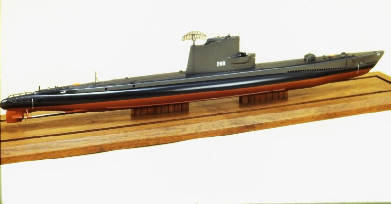
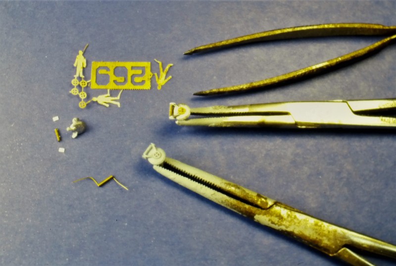
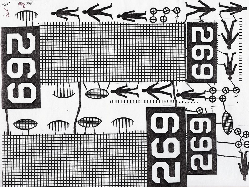
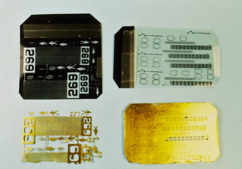
But, though we were kept busy with the defense clients, I did accept the occasion commission from private individuals. Which was the case with the subject presented here: a 1/180 scale, highly detailed model of the USS RASHER, SSR 269. The client sent me a stack of photos and his suggestion that I work up the display using the then available Revell LIONFISH plastic model kit.
The RASHER and her sisters were WW-2 era GATO class diesel boats modified to serve as radar picket submarine -- advance scouts for fleet battle groups. Hence the new designation SSR. The Migraine-3 program defined and oversaw the modification. The Migraine-3 boats, of which the RASHER was a member, were extensively reworked. They were lengthened, their stern tubes removed to make room for the increased compliment, huge air-search radars installed atop their GUPPY like sails, and a dedicated air-control center installed to coordinate friendly air operations as well as presenting the tactical situation to the battle-group Commander. But, the days of the SSR's were brief as AWAC aircraft, satellites, and SSN's quickly took over the roll of battle-group point-man.
DBF.
This picture of RASHER shows her a short time after the Migraine-3 conversion, as the bulbous height-finding radar just abaft the sail and smaller 'homing beacon' radar near the turtle-back are still in place. These items were soon removed leaving only the big sail mounted BPS-2 radar antenna to tell the world that RASHER was a radar picket submarine.
The projecting bridge 'wings' permitted the conning officer and lookouts to get a view aft without their line of sight being to badly blocked by the elongated sail.
(My apologies for the grainy quality of the following in-work and beauty shots that chronicle creation of the RASHER display. I documented this work in the late 80's, before I embraced digital photography. The pictures that follow were recently copied digitally from the original, and slightly time diminished, color slide positive film and black & white negative film I've retained through the years).
Three major tasks presented themselves as I converted the LIONFISH kit to the Migraine-3 RASHER: Lengthen the hull and capture the 'knuckle' where the forward end of the hull extension piece butted up ugly to the rest of the submarines bow; manufacture of an entirely new sail fairwater with its weird bridge wings; and creation of that big BPS-2 drag inducing parachute of a radar antenna mounted atop that sail.
THE HULL
The Migraine-3 boats were lengthened to make room for the CIC space and additional equipment.
To extend the kits hull 25-scale-feet I bought a second LIONFISH kit and grafted a portion of that to the display hull. The graft done at the hulls maximum breadth so as not to spoil the natural curve of the hull. Once the hull was lengthened I would later ugly up the hull at the point near the bow where the hull extension was performed on the actual boat.
Automotive filler -- classified as a thermosetting type plastic -- is a mixture of polyester resin and finally ground, inert 'filler' to thicken the product. The catalyzed goo can be applied, in mass, to a surface in need of re-contouring without fear of sagging. Unlike air-dry putties (like my favorite, Nitro-Stan) that can't be put on too thickly, with a catalyzed filler the thicker you put it on, the hotter it gets, and the quicker it changes state from semi-liquid to hard mass.
For this discussion I'll use the trade name of a familiar brand of filler: 'Bondo'.
The after end of the extension segment attached at or near the operations compartment forward bulkhead -- a bit forward of the conning tower-fairwater leading edge. This constant diameter extension of the pressure hull, and saddle type ballast tanks that surrounded it, resulted in a nasty looking 'knuckle' at the forward end of the extension. This, of course, ruined the smooth lines of the hull so close to the sharply curving bow. Oh, well... function over beauty, as they say.
I built an external radial frame from .065" thick polystyrene sheet. This external reference frame girdling the hull where the forward end of the hull extension piece was to be. That frame, at its outer edge, having the same geometry as the after end of the supposed extension.
I screeded on catalyzed Bondo to the height of the external frame both fore and aft, feathering the filler to the surface of the hull. With just a few careful passes of a broad bladed putty knife, I had roughed out a credible looking 'knuckle' to the hull lines forward.
Some filing and sanding, a bit more Bondo, more sanding, then Nitro-Stan air-dry touch-up putty to address file and sanding marks, yet more sanding, and the hull was ready for gray primer.
Bondo was also used to fill the concave portions of the bow and stern torpedo tube shutter doors. Also, a bit of Bondo was used to fill the gap between the wooden sail and GRP bridge structure once they were glued together.
A word to the wise: Bondo like fillers are for re-contouring and filling of significant gaps. The Nitro-Stan air-dry lacquer based touch-up putty, on the other hand, is for very shallow gaps and tool-marks.
Don't use hobby-shop sold air-dry putties or paints... they're crap; formulated to be safe, not effective. Green-Stuff and the like, if applied too heavily, will take years to thoroughly harden. Nitro-Stan is much quicker to dry owing to that products extremely volatile solvents.
Hint: If the product labeling does not warn of cancer, warts, lung damage, distemper, Ebola, or your **** falling off, the stuff is useless! The good stuff -- putties, primers, paint, and clear coat systems -- will be found at automotive supply houses and Ebay.
GLASS REINFORCED PLASTIC (GRP)
fiberglass layup is the process of forming tough, light weight, thin walled structures by encapsulating strands of fiberglass with a hardened plastic resin. The resin, once it changes state from liquid to solid, provides the stiffness. The embedded glass strands endows the structure with great strength. Just the right material from which to fabricate the open bridge structure at the leading edge of the sail.
Note the semi-circular clear spray-shield and compass repeater atop and within the open bridge cockpit.
Keep in mind, as you examine this photo, that the entire sail structure is made from three substrates: wood, GRP, and vacuformed polystyrene. Looks like one large organic structure doesn't it? The wonders of filler, putty, sandpaper, plenty of elbow-grease, primer, and paint on display here.
THIS is model building! Not something pooped out from the back-side of a Star Trek Replicator.
First, I prepared a scale three-view shop sketch of the proposed sail structure. Study of that drawing informed me as to where to employ wood, vacuformed polystyrene, and GRP.
Two slabs of pattern making wood (kiln dried and well seasoned Basswood -- these were the days before RenShape) were epoxied together, after first tinting the glue black. This produced a well defined centerline along the length of this sail blank, no matter how it was sawed, filed and sanded; the master would always present a dark centerline at all edges; that reference plane assuring symmetry between port and starboard halves as I worked the basic sail piece to shape.
However, before joining the two halves of the sail blank I laid down a square of wax paper between the halves where the eventual bridge structure would be -- I would later remove that portion of the sail and then split it along the glue plane. The wax paper made that task an easy one.
Once the glue had cured hard I razor sawed off the top of the sail -- later using that piece as a pattern for vacuforming. The forward lower corner of the wooden sail was cut away, and a tongue-and-groove indexing system provided to insure exact keying together of the two sub-assemblies.
Working the split bridge master involved extending the bridge cockpit, port and starboard, with more Basswood, those pieces screwed (and later glued) in place to the sides of the bridge master. I periodically assembled the bridge to the sail to insure a smooth transition at their mating points.
You see, to good advantage here, the dark centerline plane left by the darkened epoxy.
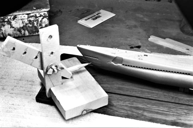
The eventual GRP bridge structure would be laid up within a hard-shell GRP tool (mold). Here I've separated the bridge master into halves and mounted them on a mold board.
The face of the mold board and masters were first waxed then given several coats of polyvinyl alcohol (PVA). These agents producing a barrier -- a mold release -- between masters and GRP used to create the tool, keeping the laidup tool from permanently (and tragically) bonding to the master and mold board.
Tool making started with brushing on a well thickened 'gel-coat' of epoxy laminating resin over the patterns and mold board. Once that layer had hardened to a tack-free state I laid on several plys of 10 ounce glass cloth, and saturated the cloth with laminating resin. After a two-day cure I popped the bridge structure tool off the masters and got to work laying up the GRP bridge structure halves.
In background is the hard-shell bridge structure tool. Mid-ground is a raw test lay-up as it looked straight out of the tool. And foreground is a trimmed set of bridge structure GRP parts that will eventually be assembled and installed to the leading edge of the wooden sail.
The completed GRP bridge structure about to be bonded to the wooden sail.
Illustrating the use of Bondo filler, Nitro-Stan air-dry putty, CA, and primer -- all employed to attach and fair in the GRP bridge structure to the wooden sail structure. Looks like hell here, but a few squirts of gray primer and it all comes together, seamlessly!
When all the smoke clears, this is the result.
Damn!... I'm good.


 [/URL]


Comment