Just lost interest in building! Moving on!
Rob
"Firemen can stand the heat"
-
-
-
Well Bob,
Nice job on the engineering! Somewhat complicated, but certainly doable. Thank you very much for taking the time to post up your designs. The function of a V tail configuration is still BIT HAZY in my mind, but ounce I have put it all together I am sure it will make sense!
Great job Bob, thanks again!
Rob
"Firemen can stand the heat"Leave a comment:
-
Alrighty. We got this licked (provided the props actually push the boat with decent thrust).
First off, let's talk linkages. The Arcturus, as I engineered these files, has a modified x-tail configuration. The control surfaces are not aligned, and the horns for each all need to point towards the centerline of the boat thanks to the limited room back there, meaning that some creative engineering needs to take place. Typically, the planes that are across from one another are in line, meaning you can connect them with standard yokes and run a single rod to the horn. Not gonna work in this case as the rotation needs to be reversed thanks to the placement of the horns. All control horns need to point toward the centerline of the boat. If you can figure out a way to get one pointing in and another out, you will be able to simplify the linkages and do away with the assembly I'm about to show you.
First off, here is the configuration with a highly technical and ultra-precise rendering of the setup:
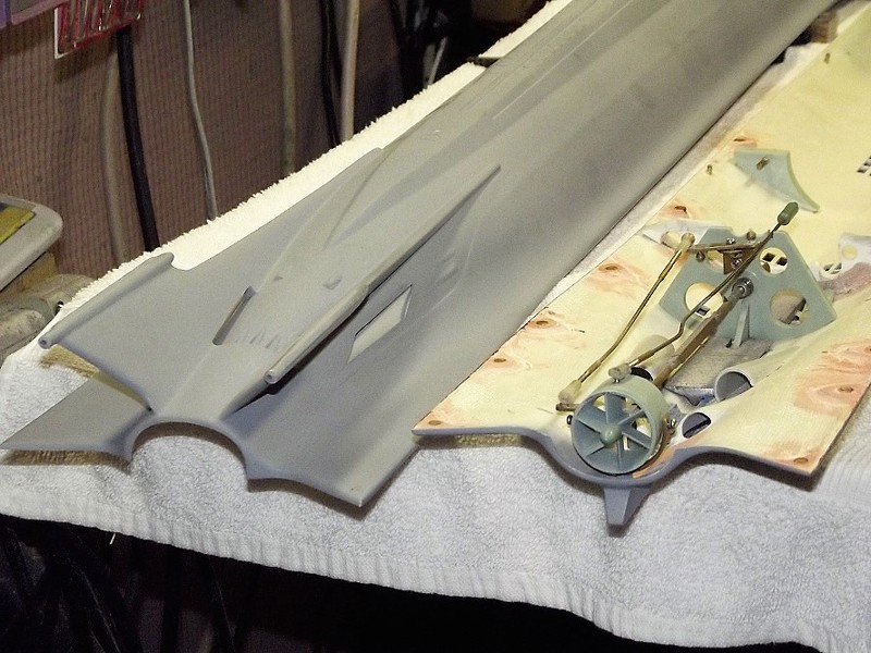
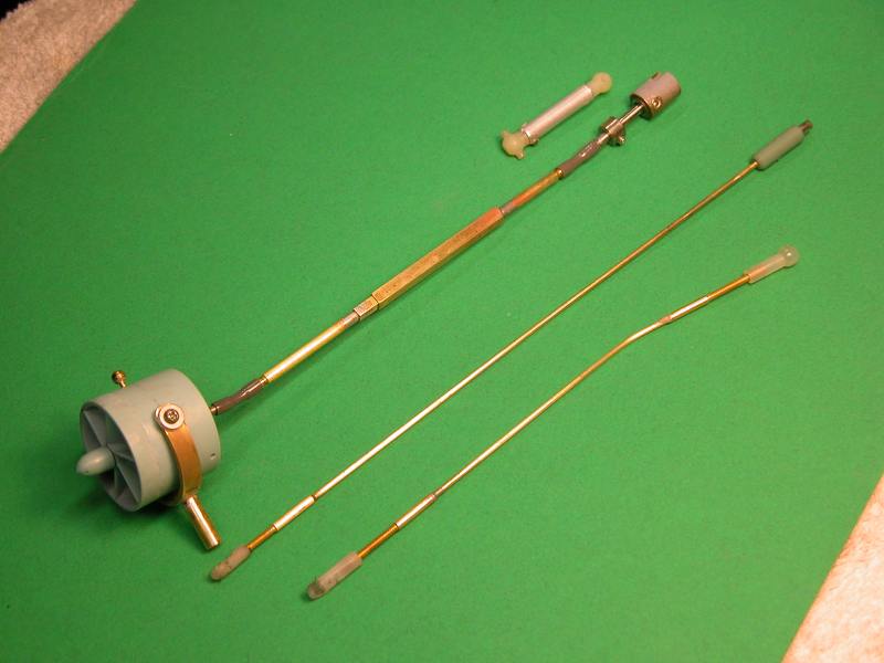
And here is the photo of the linkage assembly needed to convert the linear force in the applicable directions to each control surface:
In this setup, control surfaces 1 and 4 need to work in tandem, and 2 and 3 need to work in tandem. 1 is connected to the forward assembly under the shaft, 4 is connected to the same shaft, but above it. Move the shaft in one direction, and rudders 1 and 4 move in the same direction. Without the assembly up front, they'd move in opposite directions. Same goes for 2 and 3.
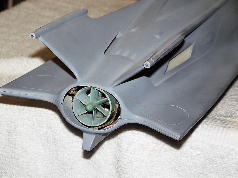
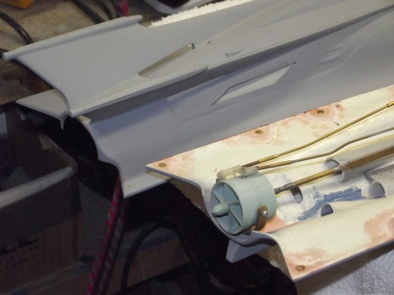
Okay, now onto propulsion. The stern is tight, especially with all the linkages coming forward from that area. That makes making room for tubing for pump propulsion very problematic. A simple 1/8" drive shaft slips in there nicely, however. All we needed to do was engineer a prop back there to push the boat.
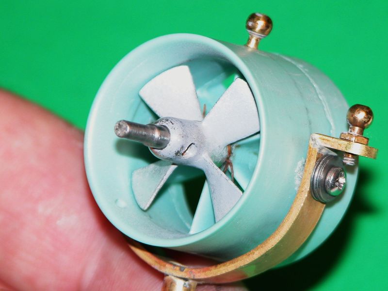
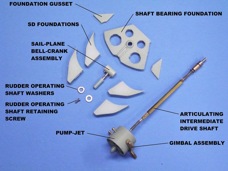
Here is the solution I came up with:
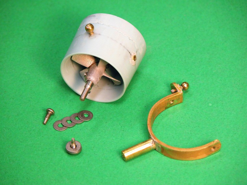
Parts needed: 20mm diameter brass props, 1/8" stainless shafts, 1/8" universal joints, 3D printed mounting bulkhead, 5/32" brass tube (for the thrust/reverse thrust bushing). It may be that we need to block the opening beside the prop shroud to stop water cycling around it, but we can test that first to see if it's needed. If we do, we might just get away with some plumbers epoxy pressed into the opening to make a nice, smooth filled pocket there. Heck, you could even sculpt in some cool venty-looking thingies, too.
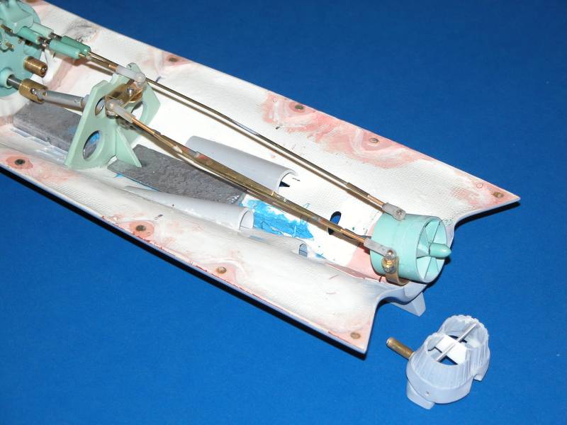
The 3D printed inserts were done on my resin printer. I tried on my filament printer, but the fitment was poor. I find that filament printers (at least mine) make parts that are about 0.2mm larger than the file dictates. This necessitates a lot of sanding for perfect fit, and these parts are pretty thin. I just used the resin printer and it fits perfectly as you see it here.
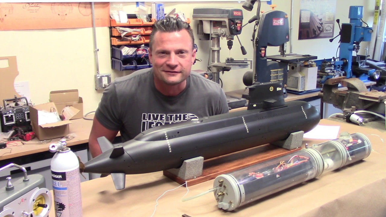
This boat will be the test bed for our upcoming 250 Series SubDriver, which I hope to have parts for within a week. Once we have the prototype cylinder assembled, we'll drop it in this boat and see what it does in the water!
BobAttached FilesLeave a comment:
-
-
Making some more progress on the hull sections!
3 more sections to go!!
Rob
"Firemen can stand the heat"Leave a comment:
-
Today I started the glue up on the bottom sections.
First 4 bottom sections went together nice and straight!
Rob
"Firemen can stand the heat"Leave a comment:
-
Hi Bob,
Ideas are flowing, and that is great! Looking forward to seeing your ideas. This boat is a bit of a challenge that is for sure, but some 1/16" solid brass rod, bender, and some solder and the linkages can be built, and with some trial and error and patience, no problem!
Looking forward to the "Dive Tribe" today!!
Rob
"Firemen can stand the heat"Leave a comment:
-
Jason and I took some time yesterday and rigged up the stern of the boat. The X-tails are a bit of a challenge as the horns for the rudders all need to face inward, and to connect the opposing planes, you need a linkage that will pull on one and push on the other. This necessitated the creation of a linkage bank just forward of Hull5. I'll have pics next week once we get the new propulsion inserts done.
The propulsion is a bit of a conundrum, as the linkages all live right where shafts go. The tiny rectangular shrouds are not conducive to circular props. I drafted an insert that will allow a pair of 20mm props to be installed back there, which should look cool, and using the higher RPM brushless motors, should get the boat up and move her along nicely.
Lots of great ideas for alternative control and propulsion here. In my mind, replacing the stock shrouds is a bit of a cheat, though they'd work really well. With x-tails, this boat will turn on a dime, so control is looked after. Just need to get it to move through the water now.
Proof of concept Monday and I'll post pics up then.
BobLeave a comment:
-
Hi Bob,
As you mentioned there may be some filament issues with this build! Nothing that cannot be remedied with a little patience and modeling skills! I have learned so much as I progress in this hobby, and one of them is sometimes things just have to be modified to make them work. No big deal at all Bob, we work with it and enjoy the challenges as they come along.
"It's still going to be one COOL build" and thanks to everyone who are posting up some great ideas!
Rob
"Firemen can stand the heat"Leave a comment:
-
I want to thank David M. for the great photos of how to do a prop driven vectoring system, and Romel for the great YouTubes on some other ideas, and also Bob Gato for the great information on a possible Kort nozzle system similar to what he did on that beautiful Atlantis build he did.
Looking into the stern of the Arcturus, it will be a challenge (which makes this hobby so great) for sure to get any type of propulsion system to work!
Rob
"Firemen can stand the heat"Leave a comment:
-
Beautiful engineering! Excellent execution! For those who are intimidated by all the non KISS parts-why not convert the pump-jet to a simple gimbaled Kort nozzle and have a stationary prop and shaft forward of it all. Not unlike what I did on the Atlantis-works well, plenty of speed, more than tight enough turn radius, and I'd do it again in a heartbeat...
Last edited by Bob Gato; 11-04-2022, 11:48 AM.Leave a comment:
-
Leave a comment:
-
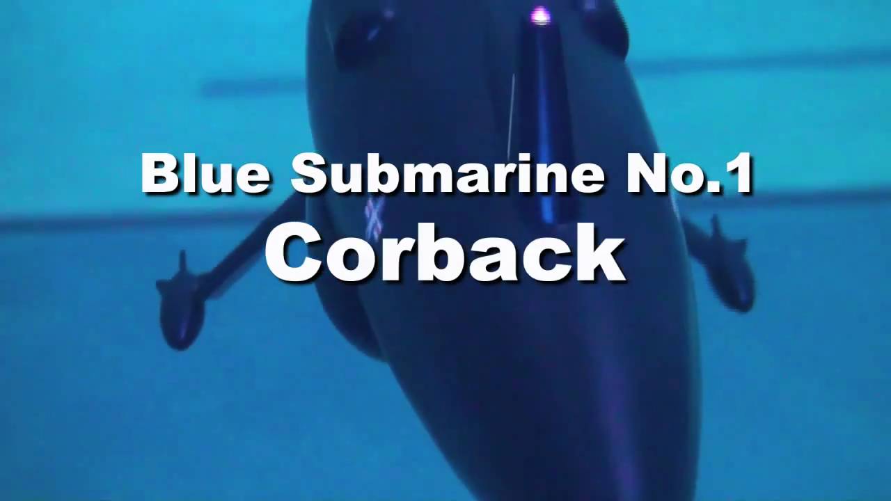
Maybe just make the lower pair of planes movable like in this anime sub.performance is same with full X tail.
Leave a comment:
Leave a comment: