Welcome to our forums. For the best in R/C submarine kits, components and accessories, be sure to visit the Nautilus Drydocks
If this is your first visit, be sure to
check out the FAQ by clicking the
link above. You may have to register
before you can post: click the register link above to proceed. To start viewing messages,
select the forum that you want to visit from the selection below.
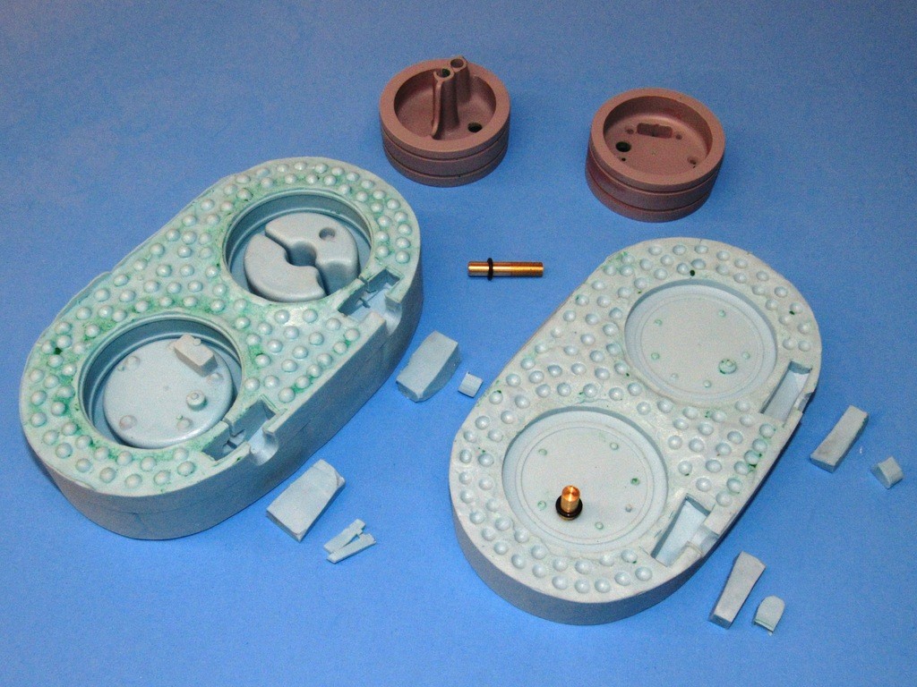
After completing the second half of the rubber tool, the halves were pulled apart, the masters removed and put into safe storage, and sprue and riser cavities cut into the top of each cavity through which the casting resin would be poured. The square-shaped riser cavities serve as reservoirs that provide enough make-up resin within the tool to back-fill the cavities which have entrapped air -- air that is only crushed into solution during tool pressurization, a point in the process where I canĺt get at the tool to pour in the make-up resin.
Note the O-ring equipped brass rod. This serves as a core piece within the forward half of the union cavity. Once a casting is removed from the tool the core is pulled out, leaving an encapsulated internal O-ring at the center of that bore -- the O-ring there to make watertight the after end of a conduit.
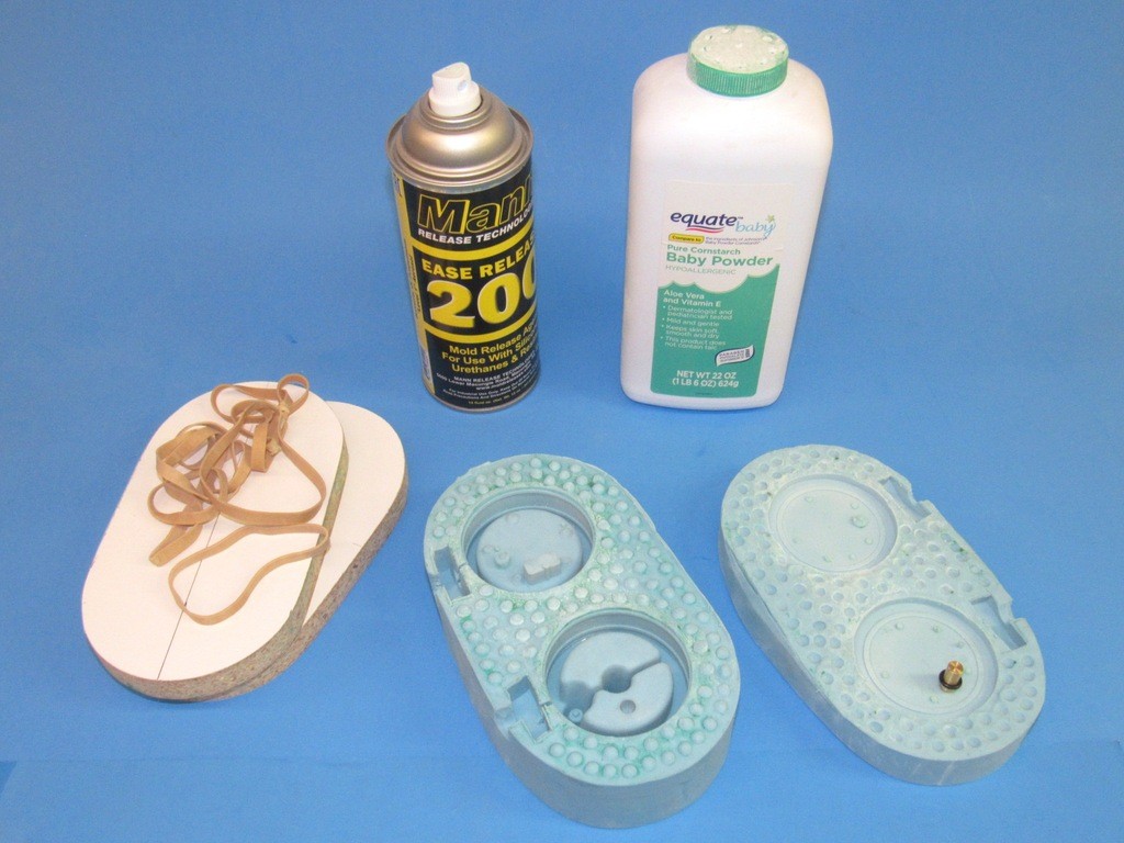
Before closing the two halves of the tool and pouring in the catalyzed polyurethane casting resin the internal cavities and flange faces of each tool half are given a good spray coating of mold/part release silicon ľ the preferred agent here is Mann ease release 200. I buy it by the case! This agent is not only good for resin production work, but is also the perfect barrier between silicon rubber elements during tool fabrication.
After spraying in the Mann 200, which minimizes any chemical interaction between the RTV rubber and casting resin (extending tool cycle life), I sprinkle on a significant amount of corn-starch or talc powder within the tools cavities, temporarily assemble the tool, shake and bang it around a bit, open it up and dump what powder that failed to cling to the sticky part-release agent onto the shop floor (that act often accompanied by Eleanorĺs non-approving Ĺlookĺ). The hydroscopic powder, clinging to the cavities surface does two things during the casting process: First, it pulls any moisture (thereĺs always water in the air) away from the cavity surfaces. And the powder acts as a wick to pull resin into tight confines; spaces within the tool cavities that otherwise would become footholds where air bubbles would reside after the resin is introduced. Such air bubble would manifest as voids on the casting, marring the surface finish of the part.
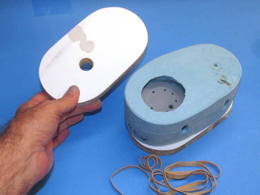
The preparatory work out of the way the tool halves are assembled and clamped tightly closed with the aid of strongbacks and rubber bands. And Iĺm ready to pour resin.
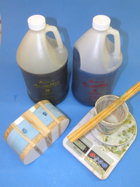
Casting resin is mixed and poured into the two sprues of the tool, filling the cavities and risers within. The tool is quickly transferred to a pressure pot, which is buttoned up and subjected to at least one atmosphere of pressure; this pressure maintained during the resin state change from liquid to solid, about a twenty-minute process when using the Ĺquick-cureĺ Alumilite polyurethane casting system.
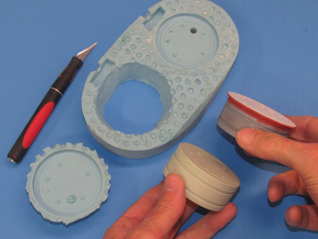
And the result: two cast resin halves of the union piece. From this point the sprue-riser elements are sawed off, the screw and pushrod bores finished on the drill press, the forward (ballast tank) half of the union tapped to accept the five 4-40 securing screws, the pushrod seal bore deepened, the emergency blow valve bore deepened, an O-ring inserted between the union halves and the unit assembled, and the union is turned on the lathe to achieve a light interference fit between union radial flanges and inside diameter of the Lexan cylinder sections the union joins.
My good buddy, Kevin Rimrodt, during a recent visit noted that I forgot to provide the forward face of the after dry space union half with a projecting flange to prevent hydrostatic pressure from pushing the union aft in the cylinders as the SubDriver is subjected to any meaningful depth of water.
Duh! Yes, Kevin. Iĺm an idiot.
Iĺll modify the after half of the master and use that to correct the tool to produce castings with that flange. Thank, Kevin. Good catch... and get that self-satisfied grin off you face!
Anyway, when you study the below photo just imagine I have that preventer flange in place. This shot shows how things look when the cylinder halves are made up to the assembled union. Holding the cylinder sections in place against pulling apart or rotating is a tightly wrapped piece of Electricianĺs tape between the two.
An O-ring watertight seal near the perimeter of the inboard faces of the union halves keeps water away from the pushrod, conduit, and fastening screw bores that run through both halves.
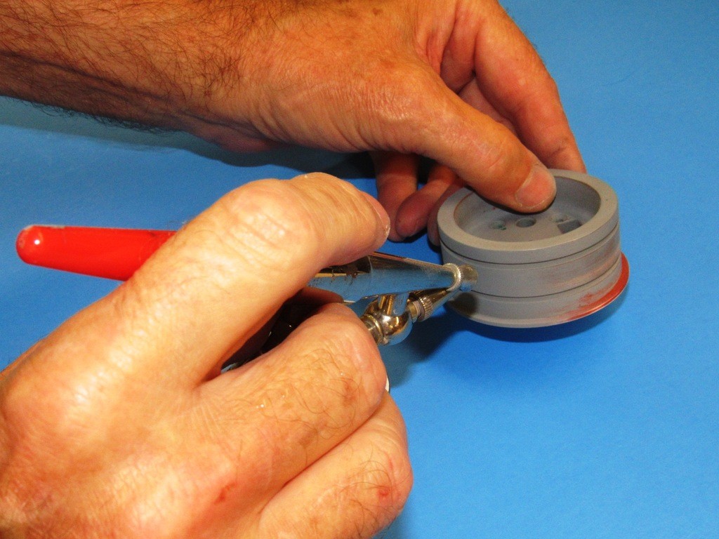
After the O-ring is seated in the grooves of the hand-held union halves, the five securing screws are inserted and tightened down, compressing the O-ring till it affects the watertight seal between the two halves.
As there is such a sloppy tolerance of diameters of Lexan cylinders marketed today I produce the union raw casting with an outside diameter considerably more than any cylinder Iĺm going to purchase. This necessitates a lathe-turning of the union piece to be a light interference fit for the specific Lexan cylinder Iĺm dealing with at the moment.
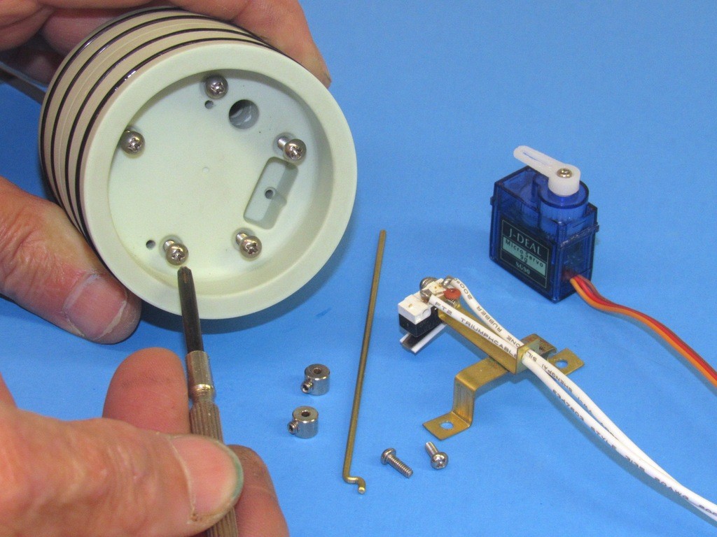
The ballast sub-system servo, its bracket (with mounted LPB limit-switch), and pushrod make up to the after face of the dry-space half of the union. The pushrod passes through both halves of the union and, at the ballast tank side of the union, emerges through a watertight seal where it makes up to the other elements of the vent valve and emergency blow valve, linkage.
Since I had my Pacemaker fitted and they told me my wife could completely control me with an r/c radio, I've had to stay well away from this hobby. (I know some of you are thankful - arseholes!) :-) However, I had news of a British ww2 submarine find, and was going to post it (see next post) and I saw HWSNBN had posted this.
It's always good to see David's posts and his tricks, and I really like this modular idea. I believe something similar was attempted several years ago, by someone called Rogue Sub or something similar. It never took off, but this will I'm sure with David and Bob working on it.
Nice to see a lot of CAD drawing going on too. Which begs me to ask the question. Why can't you just 3D print these end caps?
Someone throw a bucket of water over David, I think he just passed out!
Mike, I've successfully printed end caps, but once you turn over printing to others, you lose quality control. No way to know if their printer is quality or Chinese junk. No way to know if they'll print at 1 shell or as a solid piece. If you're talking about printing a master, then yes, very doable! The challenge is creating the CAD for conventional manufacturing, as it's easy to get carried away with the increased capabilities of printing and not think about how you'll gear up for large scale production.
Bob
After seeing the way you printed that bow section of my X Craft, (after UPS F'd it up), I'd think anything was possible with the right machine. My Dremel seems to do a pretty good and accurate job, but I'm only messing about, making small stuff. Better get Mr M up to speed on Fusion 360 or something. Ha! Ha! (Good luck with that!)
BTW Fusion 360 has the ability to import all sorts of stuff from the McMaster Carr catalog. Which save oodles of time in things like threaded parts. (But you probably knew that)
Since I had my Pacemaker fitted and they told me my wife could completely control me with an r/c radio, I've had to stay well away from this hobby. (I know some of you are thankful - arseholes!) :-) However, I had news of a British ww2 submarine find, and was going to post it (see next post) and I saw HWSNBN had posted this.
It's always good to see David's posts and his tricks, and I really like this modular idea. I believe something similar was attempted several years ago, by someone called Rogue Sub or something similar. It never took off, but this will I'm sure with David and Bob working on it.
Nice to see a lot of CAD drawing going on too. Which begs me to ask the question. Why can't you just 3D print these end caps?
Someone throw a bucket of water over David, I think he just passed out!
Bob
After seeing the way you printed that bow section of my X Craft, (after UPS F'd it up), I'd think anything was possible with the right machine. My Dremel seems to do a pretty good and accurate job, but I'm only messing about, making small stuff. Better get Mr M up to speed on Fusion 360 or something. Ha! Ha! (Good luck with that!)
BTW Fusion 360 has the ability to import all sorts of stuff from the McMaster Carr catalog. Which save oodles of time in things like threaded parts. (But you probably knew that)
BOMB-THROWER!
Stop ****ing up my WIP with this sacrilegious talk!
Stop ****ing up my WIP with this sacrilegious talk!
David
Outraged
I still know where your 'nerves' are! Enough with all that lathe work, and goopy casting resin I say! Get FUSION 360 and get with it! Do you want me to come over there and show you how to use it?
I still know where your 'nerves' are! Enough with all that lathe work, and goopy casting resin I say! Get FUSION 360 and get with it! Do you want me to come over there and show you how to use it?
OK, Iĺve finalized how the union piece between two lengths of Lexan cylinder interfaces the devices within. I kept things simple by making it a 2.5ö diameter-to-2.5ö diameter union. Owing to the unions design feature of being split into two halves, I can exploit the major advantage of the union: its ability to sleeve different diameters and/or lengths of cylinder (module) together to form a single system.
But, first letĺs look, with some detail, on how the union goes together; and how that union mounts the devices that attach to the after and forward faces.
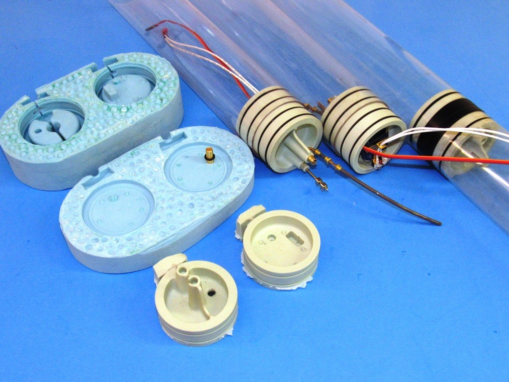
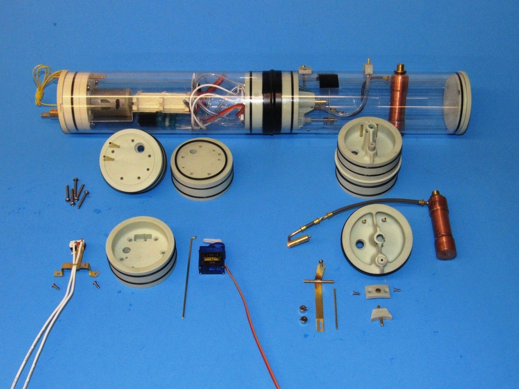
In background is a Modularized SubDriver (MSD). I have omitted the separate battery WTC for clarity. The after module (the after dry space) contains the propulsion, control, and some of the SAS type ballasts sub-system devices. The forward module (the ballast tank) is a Ĺsoft tankĺ in that it is always subject to ambient water pressure and contains the mechanics that operate the vent valve atop the tank. Also seen in the ballast tank is the emergency ballast blow sub-system -- an option for those who operate in open water.
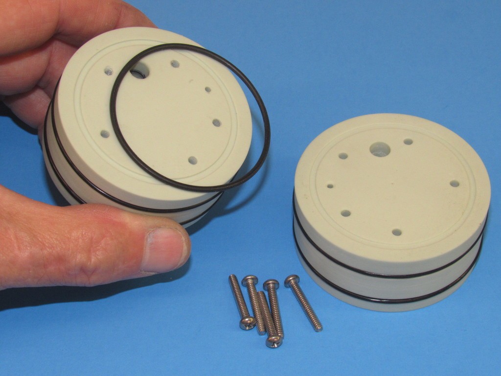
In foreground are the two halves of a union with the devices that attach to each.
Between the assembled MSD and the exploded union halves are (to the left) two union halves ready to be joined with their five securing machine screws. Note the o-ring between the halves. And (to the right) an assembled union ready to be outfitted with devices -- this union ready to join two modules together.
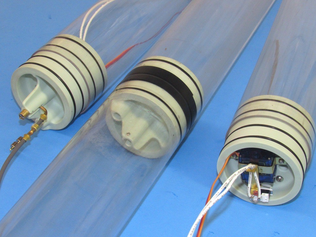
This shot of our current 2.5ö SAS type SD. Note the external plumbing, in the form of two cylinder mounted manifolds and the flexible induction and discharge hoses. So exposed, these external hoses present a likely point of failure. The MSD eliminates the external plumbing, placing all within the two modules, out of harms way.
Also illustrated here is the major shortcoming of the MSDĺs union: an increase of overall MSD length as compared to the short-of-length internal after ballast bulkhead of the standard SD design. However, that extra length is more than compensated for exploiting the unions ability to attach a larger diameter ballast section ľ for a given ballast tank volume, the overall length of a MSD with an enlarged ballast tank cylinder is significantly shorter than a SD of constant diameter.
Prototyping affirms that the mechanics dreamed up on paper, on the toilet, or during a fevered skull-session with peers actually works in the physical universe; prototype is the stark reality of what works, and what does not work.
Case in point: when I showed off the initial configuration of the union, my r/c modeling buddy, Kevin Rimrodt (always delighted to catch me in an error!) pointed out that I failed to provide a means of keeping the union from being pushed aft into the dry space by pressure exerted on the ballast tanks side of the union as the MSD experiences greater depth. He squarely put his finger-of-doom on a potentially catastrophic design error.
****!
I had to equip the after half of the union with a Ĺpreventer flangeĺ; a ring that would butt up against the forward circular edge of the dry space Lexan cylinder. The alteration of the prototype RTV tool done with relative ease, but only after I modified the after half of the union master to incorporate the preventer flange.
Only the forward face of the after union master was re-worked. A .095ö thick disc of polystyrene was glued to its forward face. The fix was quickly addressed with putty and primer, then used to modify the existing rubber tool to produce the Ĺimprovedĺ parts.
The offending portion of tool cut out, it was reassembled with the modified master installed, and a new batch of rubber mixed, de-aired, and poured through the hole in the strong-back. After the new rubber had cured, the tool was opened up, the master removed, and the tool used to produce the improved union parts.
The cast resin unions are produced with an outside diameter significantly larger than that of the Lexan tube. Iĺve done this to account for the very wide tolerance of diameter between different manufacturers and lots of product on the market.
I employed a modified face-plate as a specialized lathe holding fixture and a standard four-jaw chuck to hold the work as I refined the diameter of the union radial flanges to suit a specific inside diameter of Lexan tube.
As the MSD routs the Low Pressure Blower (LPB) plumbing internally, through the union, Iĺve eliminated most of the external flexible hose runs that were sometimes problematic with the old versions of our SAS type SDĺs.
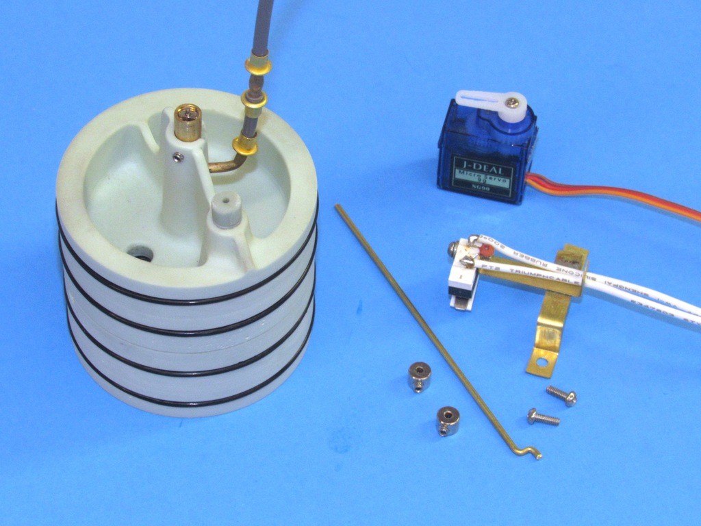
Note that the induction and discharge hoses from the LPB terminate at brass nipples set into the union. The discharge line dumps air directly into the ballast tank. The induction line continues on the wet side through a hose that makes up to the top mounted induction manifold. From atop that manifold another length of hose runs up to the top of the models sail where it makes up to the snorkel head-valve.
Iĺve retained my style of ballast sub-system linkage to open and close the ballast tank vent valve. However, there has been an active and very slick offering of alternative vent valve linkage and location at the Nautilus Drydock forum. I regard these as concepts worthy of exploration at a later date.
The single manifold glued atop the ballast tank routs the induction line that originated at the top of the submarines sail, down into the horizontal induction nipple set within the union, and on into the LPB.
I included an emergency gas blow bottle, hose, and blow valve in the MSD prototype to insure that this optional installation does not interfere with the other devices within the ballast tank.
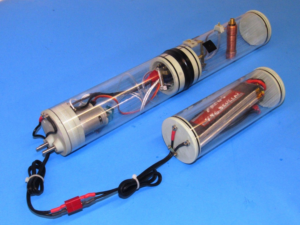
With the MSD battery power enters the after dry space through the motor bulkhead. Here are two examples of the different type motor bulkheads I developed for the 2.5ö cylinder: One a single-motor, single-shaft; and the other a two-motor, two-shaft motor bulkhead. There are other type motor bulkheads, but these are illustrative of how I make up the power cables to the devices within the MSD.
To insure watertight integrity, I use pass-through brass threaded studs through the resin bulkheads to pass the current from battery to MSD devices. The power cables are common 18-gauge two-conductor Ĺzip-cordĺ. I favor Deans connectors between the MSDĺs motor bulkhead and battery WTC power cables.
Note that strain-relief brackets are employed to prevent pulling force being presented to the points where the power cables make up to the studs.
This is how power is routed from the separate battery WTC to the MSD.
To make things water-proof (kinda) I coat over the connectors at the studs with RTV sealant. The Deans connector male and female conductors (particularly the positive conductors) are coated with silicon grease before they are made up and the cable ends of the Deans connectors are encapsulated with RTV sealant.
Yes, with use water gets into the connectors and wicks into the conductor wire. Water is insidious! But, that is easily addressed every couple of years by replacement of the cables. No big deal.


Comment