
� MOTOR AND SPARK SUPRESSION Two 40 turn, three-pole, 12-volt, brushed, 380 sized motors are mounted within the dry side of the motor-bulkhead. Each motor is spark-suppressed with two .01 micro-Farad capacitor � each soldered to the motor case and one brush pole. These capacitors store and discharge at a low RF frequency the �electrical noise� created by the arcing between brushes and commutator pads. Noise that if it got into the very tightly package array of electronic devices would drive them nuts! The two motors are wired to a single ESC in parallel, is such a way that each shaft turns counter to the other.
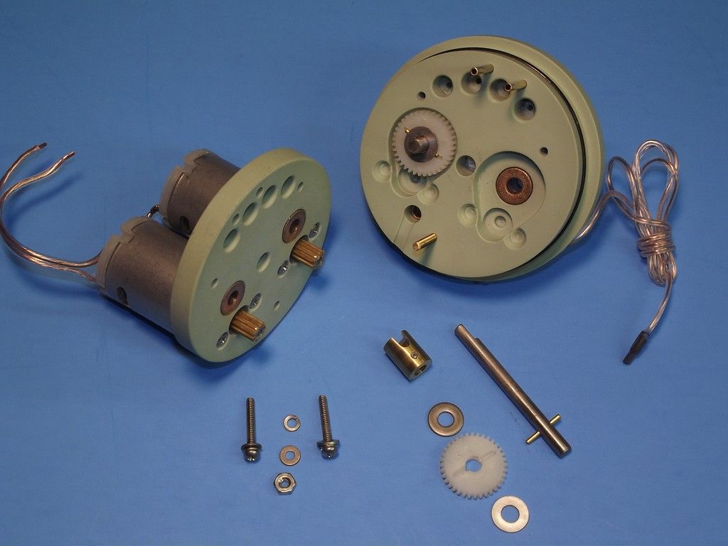
� GEAR REDUCTION To better speed-match the high RPM motors to the low RPM propellers I usually employ a 3:1 gear reduction as pictured above. The typical motor bulkhead comprises two pieces: a forward back-plate to hold the motors with their press fit pinion gears; and the motor-bulkhead proper in which are housed the drive-shafts, spur gears, and drive-shaft cup type watertight seals. The motor-bulkhead also mounts the servo pushrod seals, receiver antenna extension, and SAS suction and discharge nipples. Screwed to the forward face of the motor-bulkhead back-plate is the aluminum tray and bulkhead, upon which all the devices are either screwed or double-back taped in place. The motor bulkhead is HEAVILY populated with stuff!
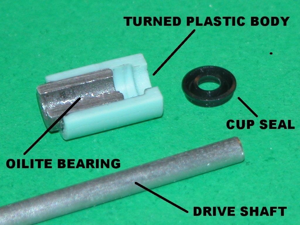
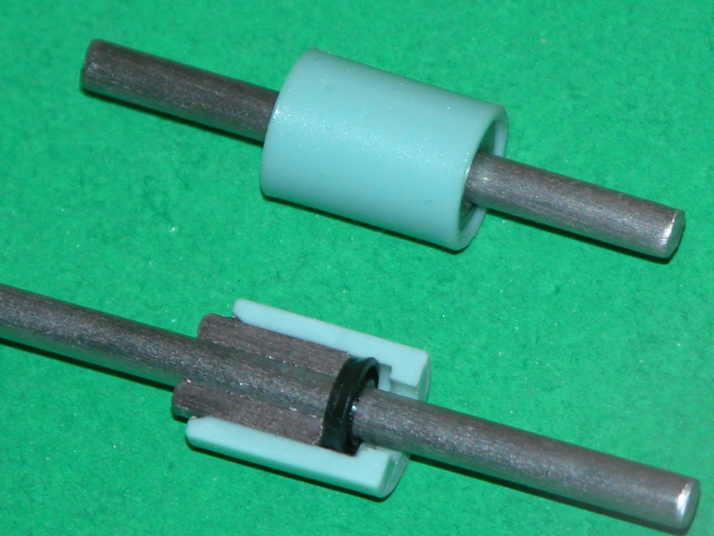
� SHAFT SEALS Each 3/16� diameter motor drive shaft is made watertight to the motor-bulkhead through a cup-seal. A cup-seal is housed within a plastic shaft seal body and the seal backed up against transverse motion by an internal Oilite bearing. Cup type seals are ideal for rotating shafts as they offer minimal friction and have the feature of increasing their sealing pressure with increasing outside water pressure. Each shaft seal unit is affixed within the motor-bulkhead with RTV adhesive � this flexible material easily absorbs vibration and can be easily defeated if the occasion arises where the shaft seal either needs replacement or repair.
CONTROL SUB-SYSTEM
The control sub-system constitutes the �brains� of the SD system; devices that take the commands that originate in your massive brain, into the transmitter, then on to the receiver where that intelligence (or an autonomously functioning environment sensing device) emerges as modulated pulse-width. Each channel from the receiver feeds a device or devices with a command from the transmitter. Then, each device either converts that intelligence into physical motion (servos), applies a voltage to a motor or solenoid (ESC and MPC), or generates a pre-set pulse-width data stream to drive other devices to a pre-set �fail-safe� position (Lipo-Guard, BLM, or ADF2).
Most of the devices are common to the average r/c model vehicle user. The servos, ESC, BEC, transmitter-receiver, battery, and connectors can be found at any hobby shop or through the Internet. However, r/c model submarining places demands on the system, and employs special devices that are only available from a few dedicated on-line services, Such as the Caswell Company � the outfit I work for. Their catalog can be seen here: http://sub-driver.com/ This outfit also supplies a wide range of SD�s for the r/c submarine modeling community.
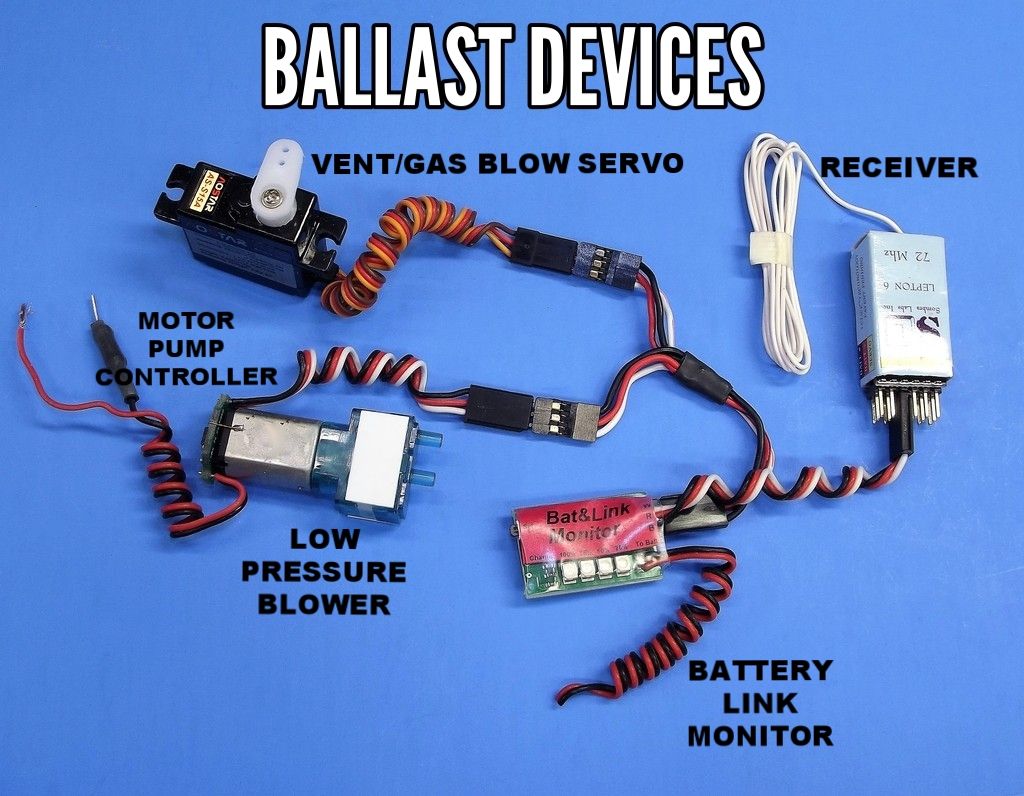
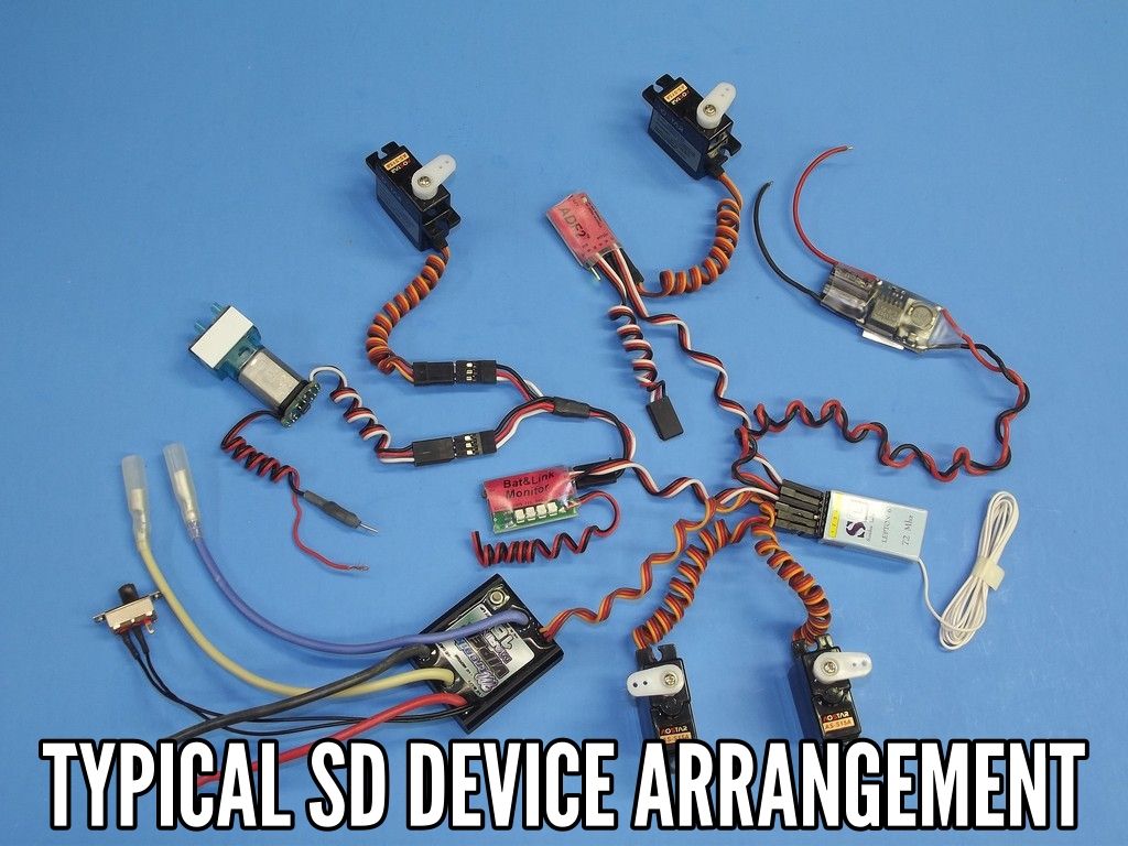
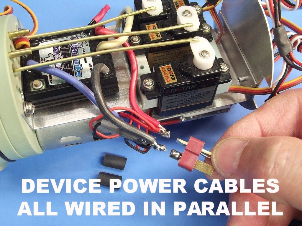
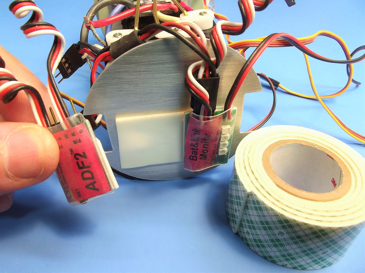
The above photo shows a typical hook-up arrangement of the devices that control, propel, and manage the ballast water aboard a SubDriver type WTC. And this is not all of it, just the devices that mount to the motor tray and bulkhead. If you look carefully you�ll see that four of these devices (ESC, BLM, MPC, and BEC) have their own red-black power wires. These red-black wires will all be ganged together in parallel and made up to a Deans male type plug which will make up to the battery cable.
� BATTERY ELEMINATOR CIRCUIT Not actually a controlling device, but vital to the whole sub-system, is the BEC, the battery eliminator circuit. This devices takes the high-voltage battery current, reduces it to the 5-volts the other devices require (distributed through the receiver bus via each devices three-wire lead). But, unlike the low capacity ESC BEC�s, this dedicated BEC has the ass to pump out a continuous 8-Ampere�s of current (enough to smoke the receiver bus foils if ever attained � but that�s another issue!). The stand-alone BEC in larger models (such as the case here) is used because of the higher stall current situations larger servos can present. The BEC is the circuit power source for all devices and as such is a vital element of the control sub-system. Smaller systems, using smaller servos, can get away with using the dinky ESC BEC.
� BATTERY LINK MONITOR/LIPO-GUARD If your system employs Lithium batteries you must have on board either the old Lipo-Guard or the recently introduced (and much more capable) battery link monitor (BLM). Both devices monitor battery voltage and work to prevent a low voltage to damage the battery. When activated, the device locks you out of the ballast channel loop, so that the model must be returned to shore for re-set � by that time even the most dense r/c submarine driver will have figured out that his battery needs replacement/re-charging. The difference between the Lipo-Gurad and BLM is the added capability of the BLM. The BLM not only protects the battery but also serves as a loss-of-signal fail-safe; real-time battery voltage meter; and r/c system performance monitor -- actually counts and displays the number of frame drop-outs that have occurred since last switching on the system.
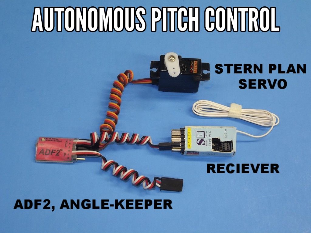
� ADF2 The ADF2 is two devices in one: An angle-keeper and a fail-safe circuit. The angle-keeper plugs into channel-5 of the receiver. The circuit employs a position sensor (accelerometer) to detect and work out the displacement of the gravity line (established during device set-up/programming) to the model submarines axis. And that is what you see in the above hook-up between the ADF2, stern plane servo, and receiver. The angle-keeper is both an autonomous artificial stabilization device � working the stern planes to keep the boat at a near a zero pitch-angle while underway submerged -- yet able to permit operator input to the stern planes; mixing both driver and angle-keeper inputs into a viable command output to the servo. The fail-safe side of the ADF2, if used, plugs into either the Lipo-Guard or channel-4 receiver port. In this example the ADF2 fail-safe circuit is not used � its lead not used.
� RECEIVER The r/c system receiver is the RF link between your transmitter and the devices that control, manage ballast water, and propel the r/c model submarine. Today�s receivers are so well designed and crafted that they have the signal selectivity to work in the very tight confines of a very RF noisy environment (The closer the receiver is to all those motors and signal-generators the more hideous becomes the inverse-square rule). Bottom line: we can cram the SD with so much stuff today and not have to worry excessively about the receiver being swamped and made stupid by all the electrical noise. At a minimum you want a five-channel receiver on any RF band below 75mHz if you want the ability to sail the model underwater with the antenna completely submerged (and then, only in fresh water). 2.4gHz r/c systems just won�t work with the receiver antenna under water.
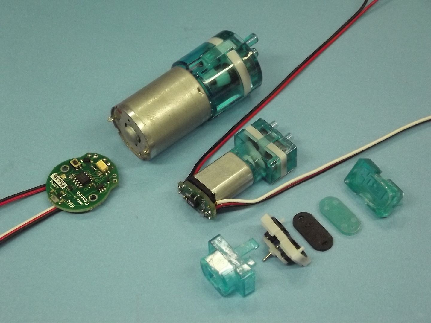
� MOTOR PUMP CONTROLLER The MPC is an electronic switch that solders directly to the back-plate of the small brushed motor that drives the low pressure blower (LPB), which produces the compressed air used to blow the ballast tank dry. The above photo demonstrates the low foot-print of the MPC. The larger unit above is used in my line of larger SD�s. The MPC gets its power from the battery cable through a voltage-dropping resister that permits the LPB motor to operate at its optimum 3-6 volts, not the 11.1-volts that comes directly off the battery. The MPC�s three-wire lead makes up to one leg of the Y-lead that comes out of the ADF2 fail-safe side or output side of the battery link monitor (BLM) � that signal shared with the ballast sub-system servo.

� GEAR REDUCTION To better speed-match the high RPM motors to the low RPM propellers I usually employ a 3:1 gear reduction as pictured above. The typical motor bulkhead comprises two pieces: a forward back-plate to hold the motors with their press fit pinion gears; and the motor-bulkhead proper in which are housed the drive-shafts, spur gears, and drive-shaft cup type watertight seals. The motor-bulkhead also mounts the servo pushrod seals, receiver antenna extension, and SAS suction and discharge nipples. Screwed to the forward face of the motor-bulkhead back-plate is the aluminum tray and bulkhead, upon which all the devices are either screwed or double-back taped in place. The motor bulkhead is HEAVILY populated with stuff!


� SHAFT SEALS Each 3/16� diameter motor drive shaft is made watertight to the motor-bulkhead through a cup-seal. A cup-seal is housed within a plastic shaft seal body and the seal backed up against transverse motion by an internal Oilite bearing. Cup type seals are ideal for rotating shafts as they offer minimal friction and have the feature of increasing their sealing pressure with increasing outside water pressure. Each shaft seal unit is affixed within the motor-bulkhead with RTV adhesive � this flexible material easily absorbs vibration and can be easily defeated if the occasion arises where the shaft seal either needs replacement or repair.
CONTROL SUB-SYSTEM
The control sub-system constitutes the �brains� of the SD system; devices that take the commands that originate in your massive brain, into the transmitter, then on to the receiver where that intelligence (or an autonomously functioning environment sensing device) emerges as modulated pulse-width. Each channel from the receiver feeds a device or devices with a command from the transmitter. Then, each device either converts that intelligence into physical motion (servos), applies a voltage to a motor or solenoid (ESC and MPC), or generates a pre-set pulse-width data stream to drive other devices to a pre-set �fail-safe� position (Lipo-Guard, BLM, or ADF2).

Most of the devices are common to the average r/c model vehicle user. The servos, ESC, BEC, transmitter-receiver, battery, and connectors can be found at any hobby shop or through the Internet. However, r/c model submarining places demands on the system, and employs special devices that are only available from a few dedicated on-line services, Such as the Caswell Company � the outfit I work for. Their catalog can be seen here: http://sub-driver.com/ This outfit also supplies a wide range of SD�s for the r/c submarine modeling community.

The above photo shows a typical hook-up arrangement of the devices that control, propel, and manage the ballast water aboard a SubDriver type WTC. And this is not all of it, just the devices that mount to the motor tray and bulkhead. If you look carefully you�ll see that four of these devices (ESC, BLM, MPC, and BEC) have their own red-black power wires. These red-black wires will all be ganged together in parallel and made up to a Deans male type plug which will make up to the battery cable.

� BATTERY ELEMINATOR CIRCUIT Not actually a controlling device, but vital to the whole sub-system, is the BEC, the battery eliminator circuit. This devices takes the high-voltage battery current, reduces it to the 5-volts the other devices require (distributed through the receiver bus via each devices three-wire lead). But, unlike the low capacity ESC BEC�s, this dedicated BEC has the ass to pump out a continuous 8-Ampere�s of current (enough to smoke the receiver bus foils if ever attained � but that�s another issue!). The stand-alone BEC in larger models (such as the case here) is used because of the higher stall current situations larger servos can present. The BEC is the circuit power source for all devices and as such is a vital element of the control sub-system. Smaller systems, using smaller servos, can get away with using the dinky ESC BEC.
� BATTERY LINK MONITOR/LIPO-GUARD If your system employs Lithium batteries you must have on board either the old Lipo-Guard or the recently introduced (and much more capable) battery link monitor (BLM). Both devices monitor battery voltage and work to prevent a low voltage to damage the battery. When activated, the device locks you out of the ballast channel loop, so that the model must be returned to shore for re-set � by that time even the most dense r/c submarine driver will have figured out that his battery needs replacement/re-charging. The difference between the Lipo-Gurad and BLM is the added capability of the BLM. The BLM not only protects the battery but also serves as a loss-of-signal fail-safe; real-time battery voltage meter; and r/c system performance monitor -- actually counts and displays the number of frame drop-outs that have occurred since last switching on the system.

� ADF2 The ADF2 is two devices in one: An angle-keeper and a fail-safe circuit. The angle-keeper plugs into channel-5 of the receiver. The circuit employs a position sensor (accelerometer) to detect and work out the displacement of the gravity line (established during device set-up/programming) to the model submarines axis. And that is what you see in the above hook-up between the ADF2, stern plane servo, and receiver. The angle-keeper is both an autonomous artificial stabilization device � working the stern planes to keep the boat at a near a zero pitch-angle while underway submerged -- yet able to permit operator input to the stern planes; mixing both driver and angle-keeper inputs into a viable command output to the servo. The fail-safe side of the ADF2, if used, plugs into either the Lipo-Guard or channel-4 receiver port. In this example the ADF2 fail-safe circuit is not used � its lead not used.
� RECEIVER The r/c system receiver is the RF link between your transmitter and the devices that control, manage ballast water, and propel the r/c model submarine. Today�s receivers are so well designed and crafted that they have the signal selectivity to work in the very tight confines of a very RF noisy environment (The closer the receiver is to all those motors and signal-generators the more hideous becomes the inverse-square rule). Bottom line: we can cram the SD with so much stuff today and not have to worry excessively about the receiver being swamped and made stupid by all the electrical noise. At a minimum you want a five-channel receiver on any RF band below 75mHz if you want the ability to sail the model underwater with the antenna completely submerged (and then, only in fresh water). 2.4gHz r/c systems just won�t work with the receiver antenna under water.

� MOTOR PUMP CONTROLLER The MPC is an electronic switch that solders directly to the back-plate of the small brushed motor that drives the low pressure blower (LPB), which produces the compressed air used to blow the ballast tank dry. The above photo demonstrates the low foot-print of the MPC. The larger unit above is used in my line of larger SD�s. The MPC gets its power from the battery cable through a voltage-dropping resister that permits the LPB motor to operate at its optimum 3-6 volts, not the 11.1-volts that comes directly off the battery. The MPC�s three-wire lead makes up to one leg of the Y-lead that comes out of the ADF2 fail-safe side or output side of the battery link monitor (BLM) � that signal shared with the ballast sub-system servo.


Comment