
NAUTILUS PART-1
I first became aware of the model work of Andreas Schmehl a few years back while checking out the articles at one of the few forums dedicated to r/c submarine model building. His work-in-progress (WIP) -- a format of article writing that is heavy on in-progress photos with supporting text -- dealt with the construction of a 1/23 scale, U-1. Germany's first combat submarine. It was the most comprehensive and well laid out WIP I had ever read.
That multi-part article had everything: CAD design, CNC'd hull masters; 3D printed detail parts; hard-shell, GRP hull tools; RTV rubber tools for the small stuff; GRP lay-up; resin casting; WTC design and manufacture; trimming; detailing; and painting.
As Andreas put it: "I mainly use CAD to create a virtual model of the hull and the interior technical structure. From that I produce the 3D files for manufacturing 3D-printed parts and for milling preforms for the GRP tooling". What Andreas calls 'preforms' we American's understand these as masters, or patterns.
Once Andreas had worked out the 'plans' in CAD, he sent the files to a second party fabricator who used them to cut machinable plastic medium via CNC milling machine, and to poop out plastic parts via 3D printer. Those parts, back in Andreas' hands, becoming the masters of off which he would produce the actual model parts.
Masters by robot. Tooling and model parts by the good doctor.
SkyNet, call your office!


His U-1 article showed me, in a very well laid out article, the use of computers and mechanized subtractive and additive item manufacture as part of the model building process.


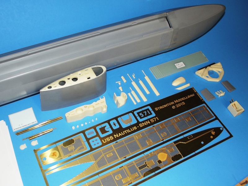
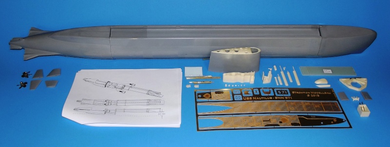
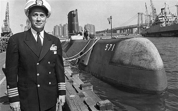
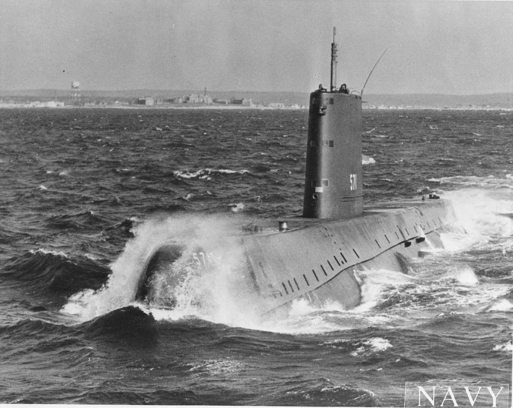
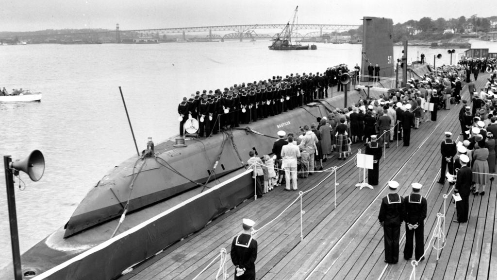
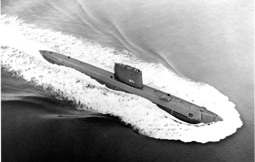
Andreas has done the same thing with his current r/c submarine project: a dry-hull 1/87 scale model kit of the famous, USS NAUTILUS.
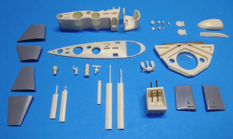
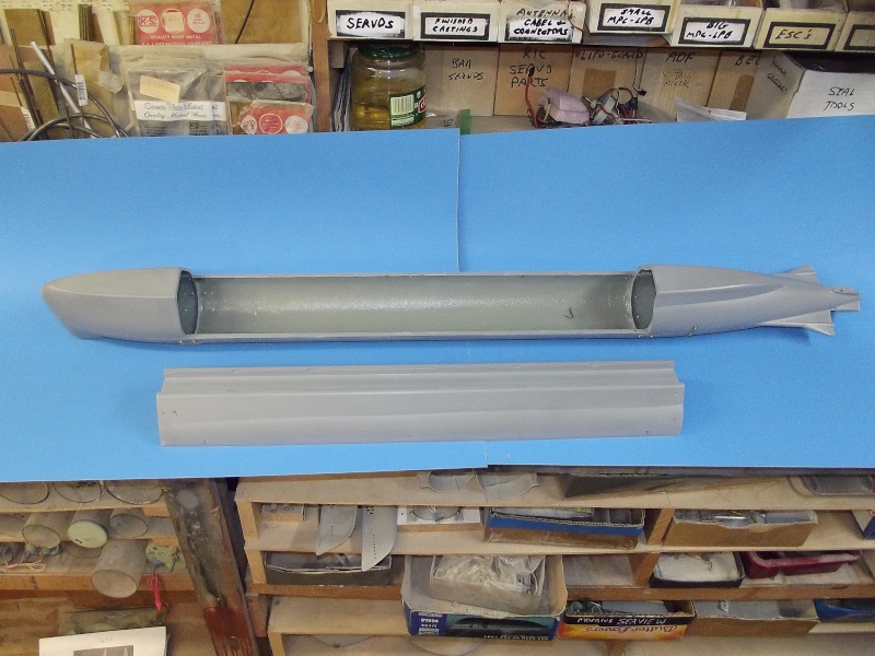
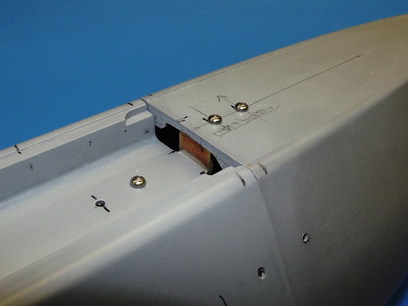
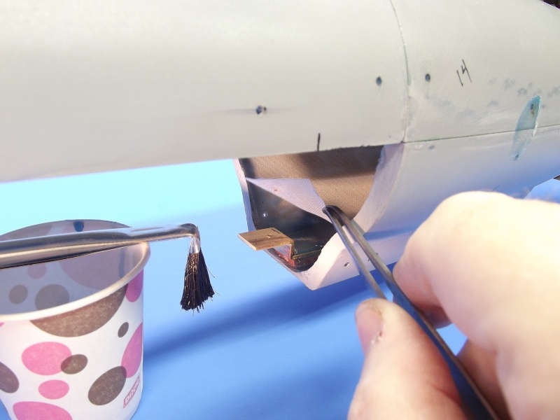
His first USS NAUTILUS, assembled from his kit -- as is the European practice -- was configured as a dry-hull type r/c model submarine. With the exception of the sail and a portion of the stern (where the stern plane, rudders and propeller shafts make up to their respective running gear and linkages) the entire hull is dry.

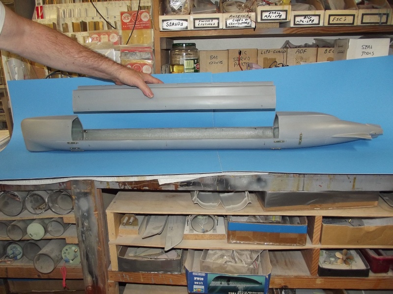
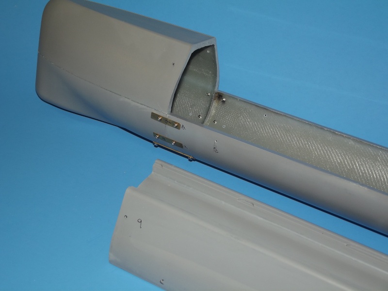
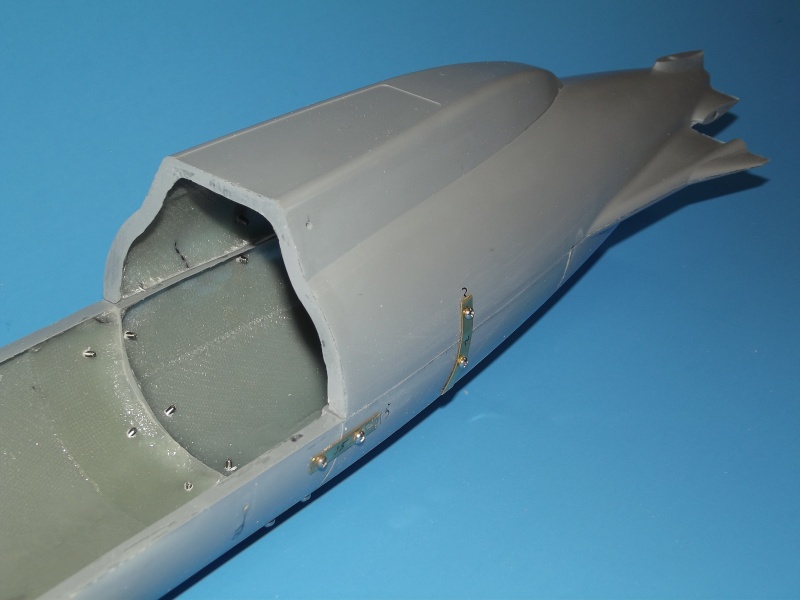
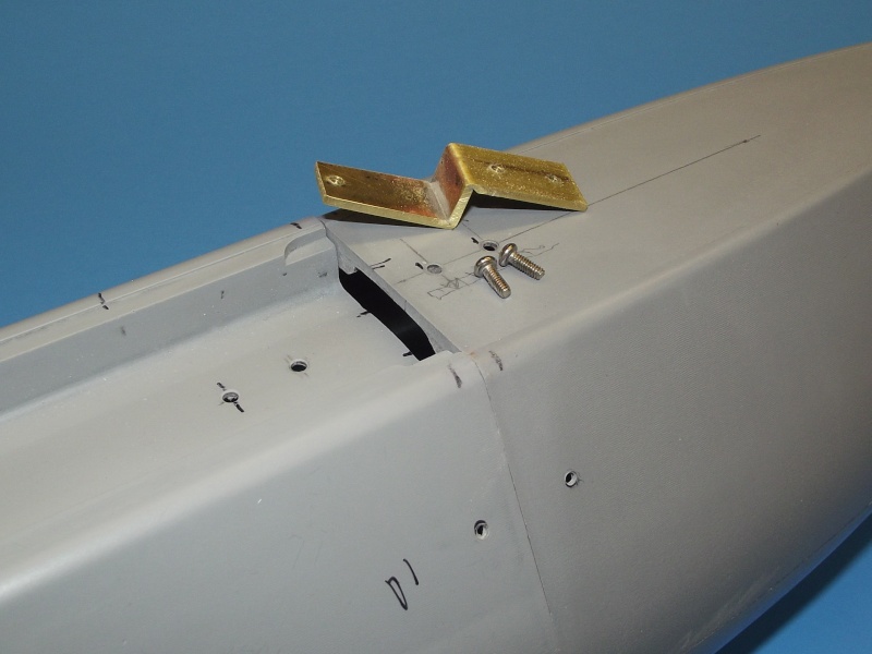
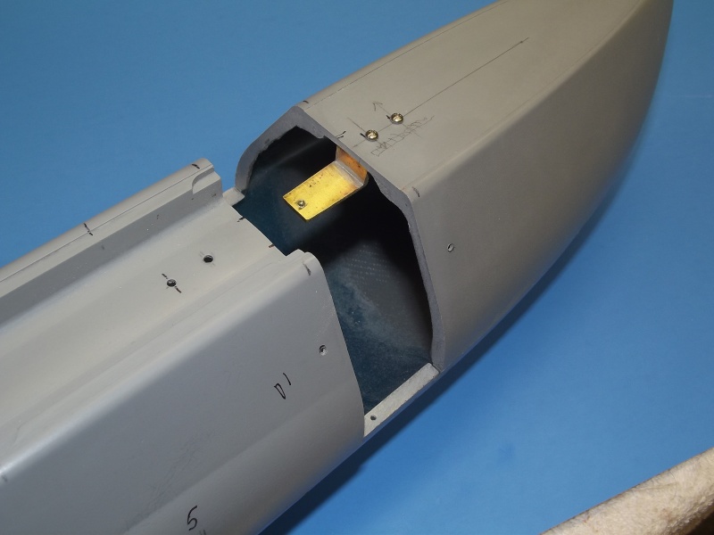
Another European practice -- most suitable for dry-hull types r/c submarines -- is to access the interior through a set of bayonet rings that seal with an o-ring. Set into the forward and after sections of the model, the bayonet rings produce a radial break between the two. To access the interior all that is required is a slight rotation of the hull halves to free the lugs of the bayonet rings and simply pull the two hull halves apart. A positive, quick, easy and pressure-proof closure method. Attaching the equipment-device mounting structure to the stern exposes everything when the forward section of hull is removed.
Unlike wet-hull type models -- which require opening the hull through a horizontal equatorial break, removing the WTC, and only then gaining access to the devices by removing the end-caps of that WTC -- the dry-hull bayonet rings make for excellent access to the internals for repair, de-watering, adjustment and maintenance tasks.

The advantage of the dry-hull is that there is plenty of available volume in which to stick all the propulsion, control, and ballast sub-systems.
However, as the superstructure and portions of hull above the waterline will displace so much water when they are immersed, it takes a great deal of water weight --- taken into an internal ballast tank -- to create the force needed to counter the buoyant force produced by all that displacing structure. A big ballast tank takes up valuable real-estate within the tight confines of the hull.
The need for such a large internal ballast tank denotes the major disadvantage of the dry-hull type submarine.


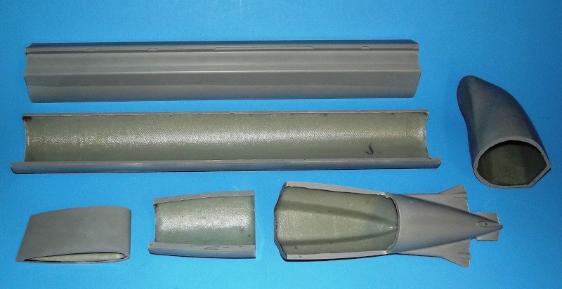
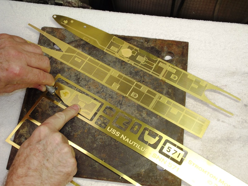
Andreas followed the same manufacturing methodology with his NAUTILUS kit. A second-party produced the masters from which he would make to tooling needed to create the model parts. Here we see some of the CNC milling-machine cut masters.

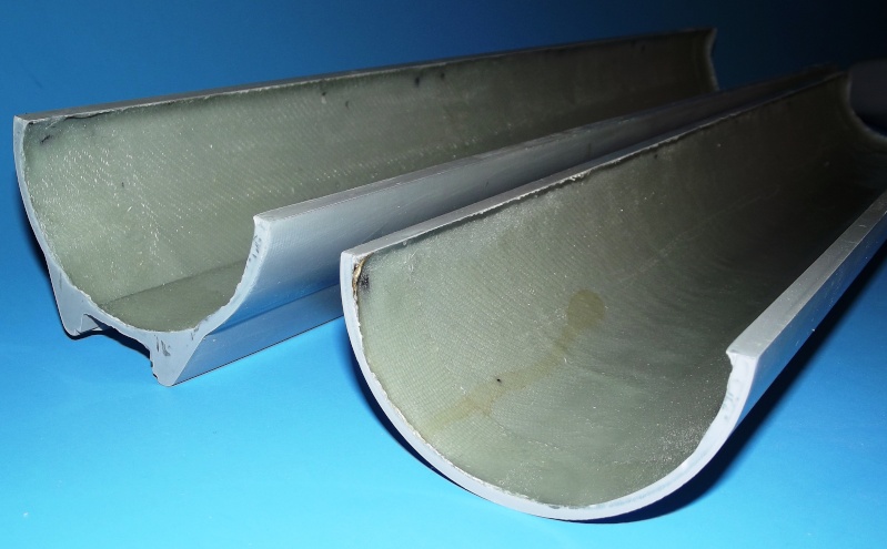
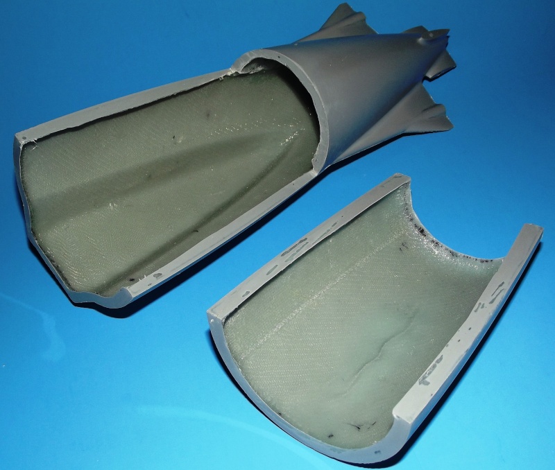
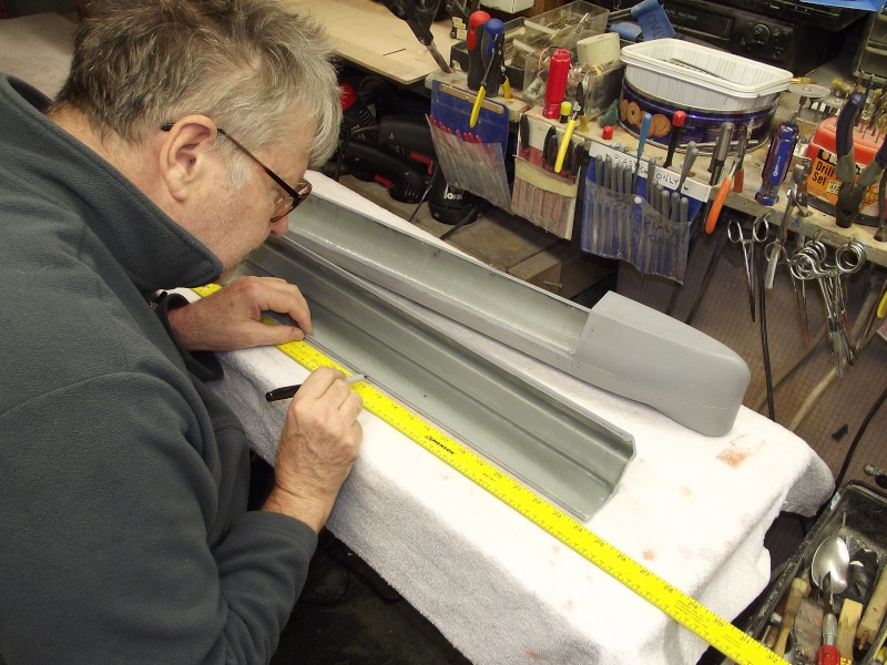
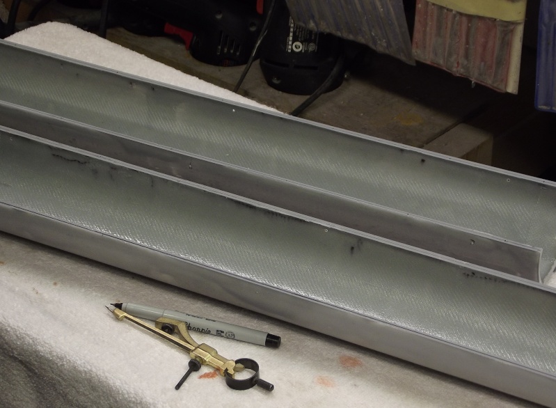
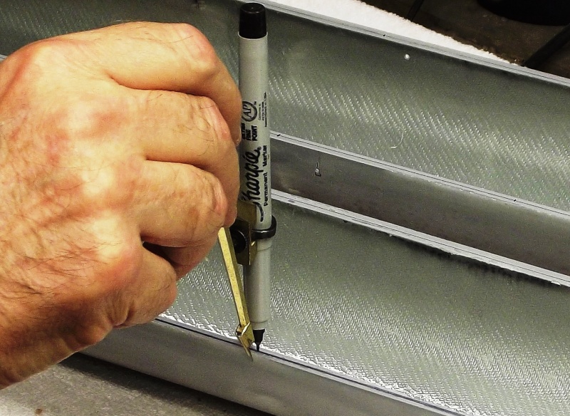
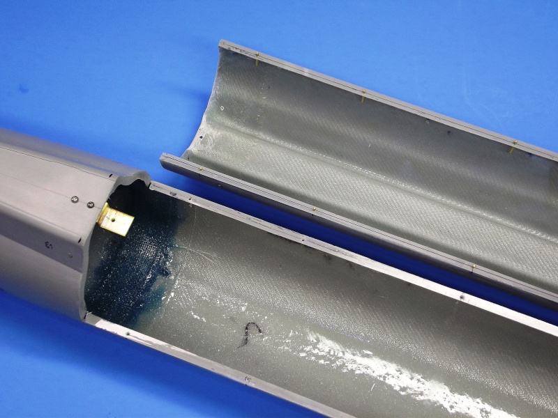
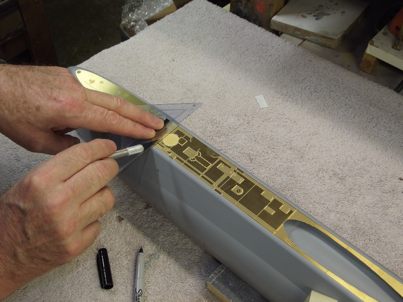
Off those CNC cut masters Andreas laid-up these GRP hard-shell tools. A total of eight tools required to render all the hull and sail parts. Those GRP parts rendered as very thin section structures.


Comment