Assembling a 1/87 USS NAUTILUS kit

Collapse
X
 
  • Time
  • Show
Clear All
new posts
  • ManOwaR
    Lieutenant Commander
    • Jul 2009
    • 217

    #46
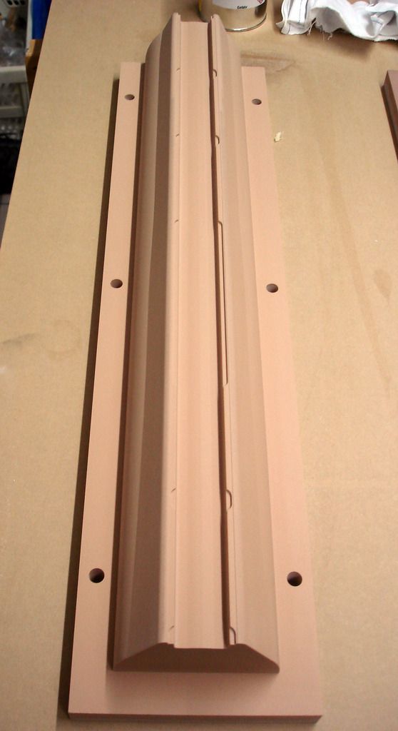
    First of all, beautiful model with a beautiful fit and finish. I'm very impressed by how precisely the photo etch fits into its allotted grooves. Actually the PE is magnificent in its own right.

    I have a couple questions directed at either Dave if he knows or Andreas. First, what type of surface coat (gel coat) is applied to the layup? And second, what method of layup was used for this model? Hand laid? Vacuum bagged?...etc

    Thx, Joel
    https://www.facebook.com/HMKcreations

    Comment

    • DrSchmidt
      Rear Admiral

      • Apr 2014
      • 1235

      #47
      The top layer is a standard epoxy gel coat. http://shop1.r-g.de/en/art/120103
      The grp is hand laid - one layer of 80g/m^2 + 2 layers of 160 g/m^2

      The precision originates form the fabrication methods and the tooling. The masters are cnc milled. The moulds are not the flimsy kind one often sees, but solid block built types. This ensures that the precision of the maters translates into the precision of the parts. And the PR decks and parts have easily tighter tolerances than the grp parts.


      Last edited by DrSchmidt; 05-05-2016, 01:44 PM.

      Comment

      • He Who Shall Not Be Named
        Moderator

        • Aug 2008
        • 13393

        #48
        The first open-water run of the 1/87 USS NAUTILUS r/c submarine kit I acquired from Germany. Produced by Andreas Schmehl this is an easy to assemble and drive r/c submarine.

        This outing presented in the following video was to establish surfaced and submerged turning radius. I find this to be a well running model submarine both on and under the surface. The initial run of this boat was in the rather confining boundaries of a local swimming pool which did not give me the opportunity to maneuver the model with any real freedom. However, that all changed when I went to some open water, as you can see in the video.

        The model employs a Caswell-Merriman SubDriver -- the system that controls, propels, and manages ballast water. The system is removable and easy access to its devices through the two end bulkheads is quick, easy, and assured. This SD, customized specifically for this r/c model submarine kit, will be available soon through the Caswell catalog.

        I have posted the video to Youtube. https://youtu.be/zRdQ-h9sORE
        Who is John Galt?

        Comment

        • DrSchmidt
          Rear Admiral

          • Apr 2014
          • 1235

          #49
          Drove mine today. Fun ride all the way. Yes, it does need space to turn when surfaced, but it turns much better submerged. I actually ran it more under water than surfaced. I had good depth control even with fixed bow planes. The rear planes do a splendid job due to their position directly behind the propellers.
          Only turn downs: Lost some paint on the lower hull due to some contact with rocks (the paint does not adhere very well...should have used an epoxy primer). And the drive battery seems to make trouble. Might just be the balancer cable.
          But all in all: The best boat I built so far.

          Comment

          • He Who Shall Not Be Named
            Moderator

            • Aug 2008
            • 13393

            #50
            Part-10

            This model kit WIP installment is exclusively dedicated to the NAUTILUS’ sail. And for good reason: Much as a scale model airplanes cockpit, the sail of a submarine model is the focal point of the viewer’s attention – the ‘front office’ of the vehicle; it’s where the machines intelligence and purpose are housed. The sail is where the people are. The sail also is one of the few places where you get a sense of the dynamic of the vehicle it represents: the optical and electronic sensors rising and descending upon their masts and faring; and It’s the last thing seen as the boat dives, and the first thing seen when it surfaces.

            As a display, the sail is the most interesting aspect of the model. One must do it justice if the display is to be attractive and interesting. The model submarines sail is the focal point of the display, have no doubts about that.

            The sail, with all those windows (deadlights); masts and fairings; antennas; periscopes; and open bridge with its deck, compass repeater, alarm boxes, platforms and such: all items that demand special care by the model kit assembler.


            Since the earliest days of submarining the conning towers -- and fairings over those conning towers if used -- featured clear windows through which watch-standers could conn the boat, surfaced or submerged.

            These windows, properly called deadlights, were quickly abandoned as pressure hull penetrations with the advent of the periscope. Deadlights of any significant size present a flooding hazard should the fragile glass lens fail as a consequence of collision or close aboard explosion. In any event, even with good underwater visibility, only on rare occasions could one see past the bow of the submarine – of little utility to the helmsman maneuvering the boat while submerged.

            From the 30’s onward submarine deadlights were relegated to the free-flooding portions of the conning tower fairing where watch standers would seek refuge against the waves while navigating the boat on the surface.

            Today, the use of sail mounted deadlights has been all but abandoned (The Russian Rubin design bureau being the last significant advocate). With the advent of nuclear power and AIP the imperative that a submarine ride out a storm on the surface was eliminated – no need for weather beaten watch standers to duck down to a protected platform and peer out through its deadlights. Today, if it’s rough, the boat submerges and everyone enjoys the ride beneath the waves – no longer must the watch standers take green water in the face while powers puking over the side as cold water streams down their backsides (I speak from grim experience!). God bless nuclear power!

            DBF … my ass!

            As built, the USS NAUTILUS featured no less than three levels within the leading edge of the sail outfitted with deadlights for outside observation. The bottom platform had three deadlights; the middle platform had five deadlights; and the bridge level platform had another five deadlights. That’s a lot of Plexiglas! The US Navy finally abandoning sail mounted platforms equipped with deadlights with the introduction of the THRESHER class submarine.


            The kit provided sail-top represents the ‘armour’ bulged top aft of the bridge opening. This bulg afforded a few inches of protection over the tops of the retractable antennas, induction, and optical heads – an alteration of the origional flat sail top, prompted by the famous under-ice exploits of this world famous submarine.

            However, my kit is being assembled to represent the ‘as launched’ boat, with the flat sail- top. I had to make a new sail-top.

            I substituted a .031” thick piece of commercially available fiberglass sheet (G-10) for the kits sail-top. This very strong material is dimensionally stable, and takes to adhesives, primer and paint very well.

            Note that the G-10 sail-top piece is temporarily held to the cast resin mast foundation piece with the aid of two machine screws (seen atop the sail-top between the masts and fairings). The ability to refine the shape and position of the many sail-top holes for wells, lookout stations, masts and fairings with the mast foundation piece out of the way makes those jobs a lot easier.


            The kits cast resin mast foundation piece – used to both provide some of the housing wells and supports of the masts and some of the antennas atop them – had its sides milled down and a good portion of its bottom cut away to reduce total weight/displacement. This one piece, as it was, displaced nearly one- ounce. After the cut-down it displaced about a third of that. That’s a lot of weight removed from the tallest point on the model, aiding greatly in keeping the models center-of-gravity reasonably low. This weight reduction would minimize heeling in tight turns on the surface, and would contribute to better static stability about the roll axis.

            Using the original resin sail-top piece as a template, I scribed onto the G-10 the sail outline as well as the shapes and locations of the holes for the bridge, lookout stations, antenna and optics retractable masts, and fairings. Those scribed lines highlighted by smearing some artist’s oil paint over the work.


            The G-10 was cut out on the band saw to outline; and the well, mast and fairing holes punched out and shaped with drills, burrs, and diamond-dust jeweler’s files.

            The only two retractable masts not represented in the raised position on this model will be the communications UHF-VHF whip-antenna mast-fairings. The top of those ‘retracted’ mast-fairings represented as engraved tear-drop shaped forms scribed upon the sail-top piece.

            An aluminum scribing stencil used here – the cutting done with two scratch-awls: a starting scriber with a sharp point, and a widening scriber with a blunt point to widen the engraved line. GRP material is very, very tough to scribe owing to the glass content which quickly dulls the steel tools, which required their sharpening several times during the course of this work.

            As a great deal of force is applied to the scribe, both down into the work and against the inside edge of the stencil, it’s a good practice to glue the stencil in place during the entire cutting operation least the stencil shift, resulting in a ruined engraving. It’s easy enough, once the scribing is done, to pop the glued stencil off the work and scrap away any remaining adhesive from the work. On occasion I will even use machine or wood screws to hold a scribing stencil down securely onto the work.

            Engraving is hard.

            Filling and fairing over screw holes and scraping away glue is not.


            While I was integrating the G-10 sail-top and cast resin foundation pieces I kept the two registered together with two machine screws that temporarily pulled the two pieces together. This permitted me to easily access both pieces, separately, as I cut out the holes for the masts through the G-10 sail-top, and worked to bore or sleeve the mast foundation piece bores to imperial sizes.

            Damned metric-system! Can’t these people count to twelve!?....


            As I stated before, big blocks of clear acrylic were employed to represent the transparent elements of the two lower platform deadlights. However, a different means of producing clear deadlights at the bridge level was required owing to the very small space between the inside surfaces of those deadlights and the front of the cast resin bridge piece.

            I opened up the deadlight openings; each framed as on the prototype, and then touched the edges of these holes with a clear self-curing resin, such as epoxy glue. Now, if those openings were small enough (they were not), the strong surface-tension of the liquid would hold its form and it would bridge the entire opening as the application tool was slowly removed. The clear resin would be left to changes state from a liquid to a solid.

            However, the larger openings, like these deadlights, require additional steps as the deadlight holes are way too big to be bridged in one glue application. Though it did not bridge the opening entirely, that first application of glue did build up a significant radius of clear adhesive at the deadlight corners and did build-up along the edges, reducing the amount of glue (and reducing the risk of introducing air-bubbles in later applications) needed to complete the bridging of the deadlight openings.

            (You plastic model plane and ship guys may recall the ‘crystal-clear’ product for representing port holes and the like – a thick, clear-drying liquid that had the surface tension to hold form once applied with a round tool to the edges of a hole. When applied correctly the goo would hold as a film within the opening where it would be permitted to harden into a not-quiet optically clear transparency).

            What David Manley taught me, and I replicated here, is to place a masking tape damn around the leading edge of the sail and apply glue from the inside, building it up thick enough to conform to the inner curvature of the sails leading edge – bridging all the deadlight openings. The outside mask insuring that the forward face of the clear glue assumed the curvature at the leading edge of the sail.

            After the clear epoxy glue has cured hard the masking tape is pulled away from the sails leading edge, the inside and outside surfaces of the clear deadlights are filed, sanded, and then polished to the contours of the sail, inside and out. Deadlight masks were applied and the black (very, very dark gray) exterior painted.

            Nothing to it!


            It’s my practice to keep as many model assemblies separable as long as possible during the course of the job.

            The entire sail assembly, only some of which you see here, is a case in point: the removable sail-top (secured to the to the sail during the in-water trimming operation and when there is a need to integrate pieces that need clearance between both sail-top and sail) permits easy access to the inside of the sail for SD snorkel mechanism integration and installation; work on the three platforms of leading edge deadlights; finish and detailing tasks to those inside surfaces of the sail seen through the open bridge and lookout stations; detailing ;installation of the sail-to-hull screw foundations; and the manufacture and fitting of the hand-rails that run both sides of the sail.


            Another departure from the kit-as-provided was to make the forward ‘tub’ -- that forms the open bridge atop the sail -- removable. Accomplished by gluing four RenShape drilled and taped foundations: two to the bottom of the sail-top and two to the back of the bridge tub. Once the sail-top is glued permanently atop the sail I retain the ability to install/remove the bridge tub as required.

            The two ‘L’-shaped brass items, each projecting from a side of the sail, are the mounts that interface the UHF-VHF whip antennas (represented by lengths of stretched sprue or cat whisker …. “here, kitty, kitty, kitty!”) with their respective ‘retractable’ fairing. A RenShape block glued to the bottom of the sail-top receives a whip antenna mount. Cut-outs in the sail-top and sides of the sail permitted each mount, with its attached antenna, to project well clear from the side of the sail.


            The completely assembled sail-top being test fitted atop the sail. Note that all the deadlight work is done and that each deadlight has been masked and dark paint applied and the masking removed to reveal the correct number and size of deadlights that, on the real thing, permit crew observation from the three platforms within the sail – but only on the surface as the entire sail (except for the bridge hatch access tunnel) is free-flooding.

            At this point the mast foundation piece will be glued to the bottom of the sail-top, the two temporary screws holding the two assemblies together removed, and their holed filled and faired over. The bridge tub will be unscrewed, removed, and set aside. And the sail-top permanently CA’ed atop the sail and the edge between sail-top and sail will be filed and sanded to the proper radius.
            Who is John Galt?

            Comment

            • MFR1964
              Detail Nut of the First Order

              • Sep 2010
              • 1511

              #51
              She runs nice David, i noticed your remark on the reduced throttle, did you tried a full 100% throttle run? or does she goes out of control at that topspeed?

              Manfred.
              I went underground

              Comment

              • greenman407
                Admiral
                • Feb 2009
                • 7530

                #52
                Originally posted by He Who Shall Not Be Named
                The first open-water run of the 1/87 USS NAUTILUS r/c submarine kit I acquired from Germany. Produced by Andreas Schmehl this is an easy to assemble and drive r/c submarine.

                This outing presented in the following video was to establish surfaced and submerged turning radius. I find this to be a well running model submarine both on and under the surface. The initial run of this boat was in the rather confining boundaries of a local swimming pool which did not give me the opportunity to maneuver the model with any real freedom. However, that all changed when I went to some open water, as you can see in the video.

                The model employs a Caswell-Merriman SubDriver -- the system that controls, propels, and manages ballast water. The system is removable and easy access to its devices through the two end bulkheads is quick, easy, and assured. This SD, customized specifically for this r/c model submarine kit, will be available soon through the Caswell catalog.

                I have posted the video to Youtube. https://youtu.be/zRdQ-h9sORE
                Good video Dave. Looks like you have yourself a winner!
                IT TAKES GREAT INTELLIGENCE TO FAKE SUCH STUPIDITY!

                Comment

                • He Who Shall Not Be Named
                  Moderator

                  • Aug 2008
                  • 13393

                  #53
                  Originally posted by MFR1964
                  She runs nice David, i noticed your remark on the reduced throttle, did you tried a full 100% throttle run? or does she goes out of control at that topspeed?

                  Manfred.
                  I did operate it full-throttle (actually 1/2 throttle as the 'throttle' end-points at the transmitter were set at 50-50%). Even then it was way, way too fast and was all over the place. Flat out it would be a frig'n rocket.

                  David
                  Who is John Galt?

                  Comment

                  • MFR1964
                    Detail Nut of the First Order

                    • Sep 2010
                    • 1511

                    #54
                    Looks the same like my V80, limited the throttle to 60%, allowing me to drive her scale-like and still fast, i did tried 100% german sportscar mode, like a bat out of hell!!!, the control was there, but you act always too late to counteract the up and down motion, even the levelkeeper couldn't run at that pace, fun to try, but a bit dangerous for my fellow submariners.

                    Manfred.
                    I went underground

                    Comment

                    • greenman407
                      Admiral
                      • Feb 2009
                      • 7530

                      #55
                      So Dave, How did you paint the Photo-etch deck plate? Normally you put on primer, then your color. I would think that too much paint would tend to hide the detail of the photo-etch. Or did I miss it?
                      IT TAKES GREAT INTELLIGENCE TO FAKE SUCH STUPIDITY!

                      Comment

                      • greenman407
                        Admiral
                        • Feb 2009
                        • 7530

                        #56
                        Also, may I ask, how did you attach the photo-etch deck plate down,as adhesive can seep into where you dont want it and ruin the detail?
                        IT TAKES GREAT INTELLIGENCE TO FAKE SUCH STUPIDITY!

                        Comment

                        • He Who Shall Not Be Named
                          Moderator

                          • Aug 2008
                          • 13393

                          #57
                          Originally posted by greenman407
                          Also, may I ask, how did you attach the photo-etch deck plate down,as adhesive can seep into where you dont want it and ruin the detail?
                          Right now the deck is temporarily attached with masking tape. When I do bond it down I'll use RTV adhesive. And that will be applied with the aid of masks that will control both the width and thickness of the adhesive -- to prevent the stuff squirting around and fouling the opening.

                          Painting PE is no problem as the photo-resist coating to the brass is very responsive to primer and paint. However, if some operation removed the coating you have to pickle the brass before it will grab primer properly.

                          M

                          Who is John Galt?

                          Comment

                          • bwi 971
                            Captain

                            • Jan 2015
                            • 940

                            #58
                            Hi David,

                            I don't want to be an smart ass here, I’m just taking my first little footsteps in cribbing, nothing compared to your experience, but I accidently made my scribing awl from a metal scriber with a tungsten carbide tip.

                            Didn’t know it at the time when I started shaping the tip.
                            But I found out very quickly that the material the tip was made off was eating my grindstone fast. I needed trueing the grinder wheel several times

                            I found out the tip was made from tungsten carbide, it is only half an inch long and glued into the holder.
                            It took me some time to shape the tip, but I eventually got a scribing awl that will last forever even in GRP.

                            Just wanted to share, no more no less.

                            Grtz,
                            Bart


                            Practical wisdom is only to be learned in the school of experience.
                            "Samuel Smiles"

                            Comment

                            • He Who Shall Not Be Named
                              Moderator

                              • Aug 2008
                              • 13393

                              #59
                              Originally posted by bwi 971
                              Hi David,

                              I don't want to be an smart ass here, I’m just taking my first little footsteps in cribbing, nothing compared to your experience, but I accidently made my scribing awl from a metal scriber with a tungsten carbide tip.

                              Didn’t know it at the time when I started shaping the tip.
                              But I found out very quickly that the material the tip was made off was eating my grindstone fast. I needed trueing the grinder wheel several times

                              I found out the tip was made from tungsten carbide, it is only half an inch long and glued into the holder.
                              It took me some time to shape the tip, but I eventually got a scribing awl that will last forever even in GRP.

                              Just wanted to share, no more no less.

                              Grtz,
                              Bart


                              There's only one thing harder than that. Good stuff, Bart.
                              Who is John Galt?

                              Comment

                              • He Who Shall Not Be Named
                                Moderator

                                • Aug 2008
                                • 13393

                                #60
                                Part-11

                                I assembled this NAUTILUS kit as a ‘wet-hull’ type r/c model submarine. The hull and sail are free-flooding and the only spaces aboard that are dry are those two compartments at either end of a removable cylinder. This water tight cylinder (WTC) -- also referred in Europe as a ‘module’ … or, ‘Tupperware’ when they’re in a particularly mischievous frame of mind -- contains the three basic sub-systems needed to animate the model submarine, endowing it with the ability to cruise either on the surface or submerged. Propulsion, control, and ballast.

                                Pushing out ballast water is done either by water pump, air-pump, piston, an onboard gas, or a combination of methods.

                                The removable cylinder concept has been around since the 60’s and commercial product since the late 80’s.

                                (For the Record: In the States credit for the design and continued development of the WTC is mine. In Europe I believe the lion’s share of credit for what they call a module goes to Brittan’s Nick Berge – one of the most prolific and out-of-the-box thinkers this hobby has ever had. In the days before the internet Nick and I worked toward development and promotion of similar systems, initially we were not aware of the others similar work).

                                Typically a WTC is divided into three sections, partitioned by four bulkheads -- one at each end, and two near the center of the cylinder. Between the two internal bulkheads is formed the WTC’s ballast tank. There are variations on this theme. The work of Ron Perrott http://www.rcsubs.co.uk/ and Norbert Bruggen come to mind, but for brevities sake I will focus specifically on the 3” diameter, two-motor-two-shaft SAS type SD worked up for the 1/87 USS NAUTILUS kit – the subject of this rather comprehensive WIP.

                                Most WTC’s differ as to materials and method of ballast water management. The WTC is an old idea: I have a picture of what otherwise looks to be a current version of a clear cylinder WTC from an old issue of Model Boats dated 1967. However, its cylinder was formed from Acrylic plastic – a material prone to cracking and difficult to machine. Today most clear cylinders are formed from Lexan, the same tough clear plastic used for soft-drink bottles and clear r/c car bodies.


                                And here we have the WTC ‘system’ – a self-contained, removable, easily accessed water tight cylinder that contains the three sub-systems needed to effectively animate an r/c submarine: propulsion, control, and water ballast.

                                Atop is an assembled, outfitted, tested, and operational SubDriver (the proprietary name given our extensive line of WTC’s). These two sized and arranged specifically for the 1/87 scale USS NAUTILUS. Pictured are the significant components that go into the manufacture of this SubDriver (SD).

                                Four cast resin bulkheads divide the Lexan cylinder into three sections. The after dry section contains the propulsion and control elements; the center section forms the ballast tank; and the forward dry space houses the battery and mission switch.


                                Examine the above cut-away examples of a typical WTC bulkhead and pushrod watertight seal to get an idea how the conduit, bulkhead, and pushrods are made watertight to the SD.
                                All four resin bulkheads are made watertight to the cylinder through edge sealing O-rings. The conduit -- a brass tube that running the length of the ballast tank -- is made watertight to the ballast bulkheads via partially encapsulated O-rings during bulkhead manufacture.

                                The pushrod watertight seals are descrete items that are RTV’ed into holes punched through the motor and after ballast bulkheads. Each pushrod seal features a 1/16” diameter bore with an encasulated O-ring at the seal bodies center which effects the watertight seal between its axial running pushrod and SD proper. The three pushrods that project aft make up to the stern plane, rudder, and bow plane linkages – all of which are external of the SD and make up with magnetic connectors. A single pushrod passes between the dry and wet side of the after ballast bulkhead and is part of the linkage that controls the operation of the ballast tank vent and emergency gas blow valve.


                                Three servos are mounted on the motor-bulkhead device tray. The one about to be made up to its 1/16” diameter brass pushrod drives the stern planes. This servo is tended by the ADF2 angle-keeper circuit (with operator input always available); the middle servo is for the rudders; and the port servo operates the bow planes.

                                Each servo pushrod goes through a watertight seal set into the motor-bulkhead. Those seal bodies made fast with RTV adhesive – this permits easy replacement if called for.


                                Like cramming ten-pounds of stuff into a five-pound bag!

                                That’s always been the situation with r/c model submarines. As illustrated here. All the devices that have to fit, coherently, onto the motor-bulkhead device tray and bulkhead can now be fit into a very tight package. Only with the development of small footprint devices (computer assisted circuit design and surface mount technology) and very selective receivers (signal processing in addition to detection) has this magic-trick been possible. Device size and receiver selectivity has been a boon to this hobby.

                                Pull the motor-bulkhead away from the cylinder and there are only two electrical connections to break to free the entire unit from the system: one pair of plug connectors interface the motor-bulkhead to the battery power cable, and the lead going to the ballast servo mounted to the dry-side of the after ballast bulkhead.

                                In order to better describe the function and arrangement of three sub-systems, I’ll discuss each in some detail with supporting pictures:

                                PROPULSION SUB-SYSTEM

                                The devices regarded as belonging to the propulsion sub-system include the battery, Electronic Speed Controller (ESC), mission switch, battery cable, battery, cable plugs, motors, motor spark-suppression, gear reduction and propulsion shaft seals.


                                · BATTERY This particular SD is sized to fit the 1/87 USS NAUTILUS kit. As I found the size of the ballast tank left little room for both the forward and after dry spaces, this necessitated the use of ‘short’ 11.1-volt Lithium-polymer batteries. Two of these short batteries, wired in parallel, achieved the 3-Ampere hour capacity needed to keep the model running for a few hours between charges. Note the use of a three-plug adapter used to gang the two batteries together in parallel, permitting me to retain the original battery discharge plugs. One of these ganged batteries made up to the foreground motor-bulkhead devices through a test/set-up power cable – this cable making set-up of the installed devices an easy matter, and is a perfect analog to the one that runs through the SD’s conduit tube.

                                · ESC The electronic speed controller is a common, commercially available item that directs battery current of the desired polarity and intensity to the motor(s) as commanded by the transmitters throttle stick. I’m a big fan of the Mtroniks brand of brushed motor ESC’s. These units are waterproof, robust, and easy to program, and feature a relatively small footprint for the work they do. It’s a good practice to select an ESC with a maximum sustained current draw that approximates 2X the stall current of the motor(s) it’s connected to. For this application, where I’m driving two motors in parallel, I’ve found the fifteen-Ampere Mtroniks ESC to be more than adequate to the task. Though provided, you do not use the ESC’s battery eliminator circuit on the larger SD’s – it simply does not have the current capacity to meet the load presented to the receiver power bus. Either snip off or pull clear of the ESC’s lead the red wire to disable the ESC’s BEC …. NOT THE BLUE WIRE, OR WE ALL DIE IN A HORRIBLE EXPLOSION (for you WW-2 movie fans out there).


                                · MISSION SWITCH The entire system is powered through a single battery – which provides power to control, propel manage ballast water. The mission switch is a simple, series connected single-pole, single-throw toggle-switch rated for 10-Amper’s at 110-volts. The on/off function is done at the forward face (wet side) of the SD’s forward bulkhead – simply flipping the toggle to either the ‘on’ or ‘off’ position. The switch itself is made waterproof by a rubber boot that fits over the toggle and makes a watertight union to the face of the bulkhead through an O-ring. The mission switch is wired in series to the battery power cable – the wiring passing through a strain-relief block within the forward bulkhead, its job to prevent breakage of the wires at the switch terminals during handling.

                                · BATTERY POWER CABLE To be capable of handling up to a sustained 20-Ampere’s at 12-volts it’s two conductors are of 16-gauge; enough copper cross section to preclude any significant voltage drop or heating. This is the main-line between the battery and all the devices requiring electrical power in the after dry space. The power cable runs aft through the brass tube conduit within the central ballast tank. A male Deans-plug at the forward end makes up to the battery (parallel battery harness in this case), and a female Deans plug at the after end of the cable makes up to the devices female Deans plug off to the side of the motor-bulkhead device tray, within the SD’s after dry space. As pictured below.


                                · CABLE PLUGS As mentioned, the power cable plugs are of the Deans type. These are polarized to prevent accidental polarity screw-ups when making up the battery and devices to the power cable. Though four devices get battery power direct (BEC, MPC, BLM and ESC), it’s the ESC we’re interested in here. This vital propulsion device gets the lion’s share of current when the propulsion motors are running and accounts for why the power cable and connecting plugs, and mission switch are of such a robust nature.


                                ·
                                Who is John Galt?

                                Comment

                                Working...