Welcome to our forums. For the best in R/C submarine kits, components and accessories, be sure to visit the Nautilus Drydocks
If this is your first visit, be sure to
check out the FAQ by clicking the
link above. You may have to register
before you can post: click the register link above to proceed. To start viewing messages,
select the forum that you want to visit from the selection below.
So this answers, I think,a previous question I had raised about the photo etch kit I ordered for the Gato. The sheet must be ever so slightly recessed into the deck, your Nautilus model comes with that recess. The Gato does not. So that means Ill have to make my own recess of sorts on the Gato. Right Dave?
IT TAKES GREAT INTELLIGENCE TO FAKE SUCH STUPIDITY!
So this answers, I think,a previous question I had raised about the photo etch kit I ordered for the Gato. The sheet must be ever so slightly recessed into the deck, your Nautilus model comes with that recess. The Gato does not. So that means Ill have to make my own recess of sorts on the Gato. Right Dave?
Depending on the yard the deck planking was set either flush or raised over the superstructure (by the thickness of the planks). Such details make you ****ing crazy!
That is the truth, David. The Gato can offer so much opportunity for the detail freak to manfredize their sub at the same time pull out any remaining hair you have.
If you can cut, drill, saw, hit things and swear a lot, you're well on the way to building a working model sub.
Basic hull assembly done, it came time to address the control surface linkages, running gear, and the removable SubDriver (SD, also known as 'water tight cylinder') foundations. I first replaced the kit provided metric sized control surface operating shafts and propeller shafts with slightly smaller units sized to the imperial system.
� Hey, this is America! We don't do no stik'n metric!
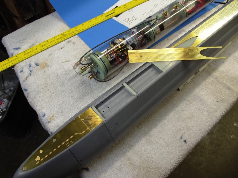
I also took the opportunity to test fit the sail atop the hull as well as checking the fit of the four acid-etched deck pieces.
The primary objective here was to get everything that movies on this model to work correctly from the source, the SD.
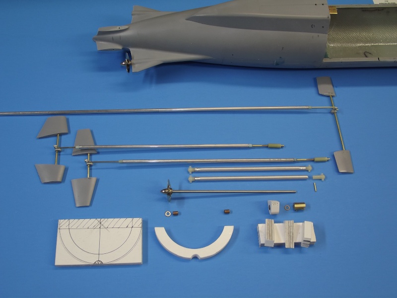
The kit provides all the parts and documentation needed to produce a very credible model of the USS NAUTILUS. However, other than the way the hull parts break down, provision of propeller shafts, control surface operating shafts, and perfectly formed and positioned propeller shaft bores (stern tubes), it's the job of the kit assembler to come up with the hardware and devices required to convert the kit .
The control surface linkages, some elements of the running gear, and means of mounting the SD (which contains those control, propulsion, and ballast sub-system elements that must be housed in a dry environment) have to be fabricated or purchased separately by the customer. You see some of that work above in the form of linkages, running gear, and SD mounting hardware.
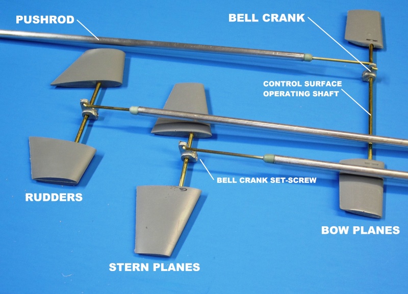
All three sets of control surfaces (stern planes, rudders, and bow planes) are simple affairs: Each set of control surfaces has a straight run-through operating shaft -- there is no need to provide shaft avoidance yokes, which is the case in most single-shaft designs. The two shafts of the NAUTILUS provide plenty of clearance in the stern for straight-through stern plane and rudder operating shafts -- a desirable situation also made possible by the two sets of operating shafts being well distanced longitudinally.
The cast white metal bell-cranks were at hand: these are parts of my own manufacture, used in our line of plastic model submarine fittings-kits. Each bell-crank secures to a control surface operating shaft with a set-screw. One control surface is permanently glued to one end of its operating shaft while tihe other is made to be a tight inpppterferrence fit to the other end of the operating shaft. To install a set of control surfaces the shaft is inserted part way through the hull, and the bell-crank (with pushrod made up through a Z-bend) pushed onto the end of the operating shaft, and the shaft pushed through the opposite hole, and the other control surface pressed into place and twisted into alignment with the other control surface. The bell-crank is then centered onto the shaft and its securing set-screw tightened.
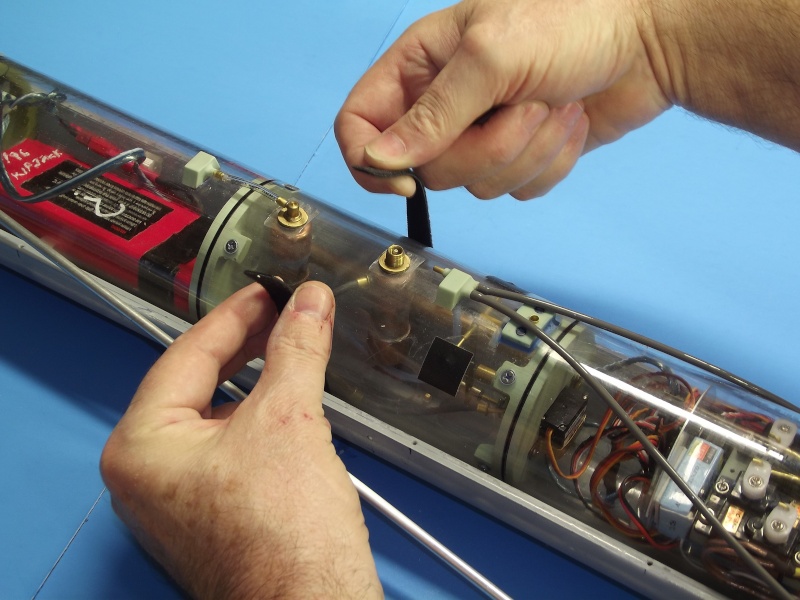
You'll note the use of a large diameter (1/4") aluminum pushrod -- here, made up to the bow plane operating shaft bell-crank. This light weight, yet stiff, pushrod prevents flexing as the control surfaces are positioned against the load presented by flow forces. Each end of a pushrod terminates in 1/16" brass rod. These rods suitable for make up to the bell-crank through a Z-bend at one end, and a magnetic couplers at the other end of the pushrod. In the above photo you can make out the securing set-screw of the bell-crank which makes it fast to the bow plane operating shaft.
Interfacing the small diameter brass rod and the much larger diameter aluminum tube is an adapter. This adapter made from a sprue of polyurethane resin, bored and turned to integrate the brass and aluminum pieces. The assembly made fast with CA adhesive.
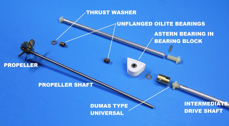
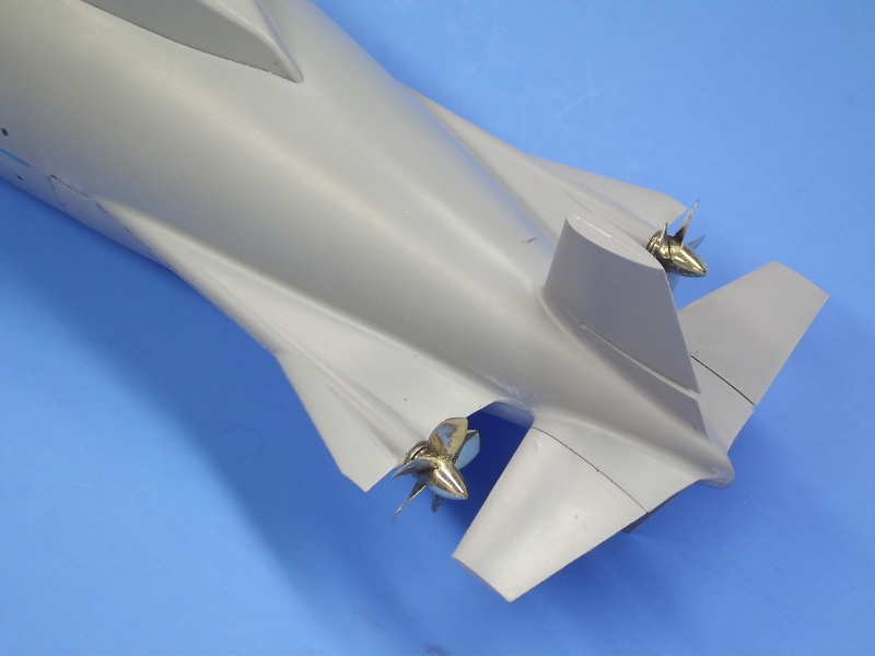
Working out the running gear on this NAUTILUS model is easy: The two beautifully cast and finished brass propellers, and a molded in place propeller shaft bore (stern tube) that runs straight and true through each horizontal stabilizer are provided. All that is required of the kit assembler is to procure and install an un-flanged Oilite bearing at each end of a stern tube; come up with bearing blocks and an astern bearing; and provide intermediate drive shafts that fit between the propeller shafts and SD motor output shaft through universal couplers.
The after Oilite bearing, against which the propeller pushes, serves to transmite the 'ahead' thrust load to the hull. The forward most bearing addressing the backing thrust load through its bearing block which is bonded within the hulls stern.
Beautiful, isn't it? Other than just a little file work to knock down some flash at the peremeter of the appendages, I have not done a thing -- this is how tight and clean the stern is once the parts are assembled. This kit is a marvel of precision, good kit design and manufacture on display!
Into the extreme after end of the stern tubes are set and glued ahead Oilite bearings, against which is a thrust washer, pushed against by the face of the propeller hub.
The GRP stern piece comes to the customer assembled with a perfecty true stern tube through which each propeller shaft passes. As mentioned before, I substituted imperial sized shafts for the kit provided metric. As this undersized those items it was an easy matter to sleeve up the control surface operating shaft openings (which make for simple bearings) to pass the shafts that operated the rudders, stern planes, and bow planes.
At the stern, the only tricky task was to lathe turn the little 1/4" outside diameter intermediate and ahead Oilite bearings. This operation required to make them fit the existing propeller shaft stern tube bore. Stock 1/4" outside diameter astern Oilite bearing were placed in custom made 'astern thrust blocks'.
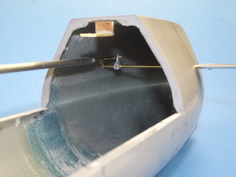
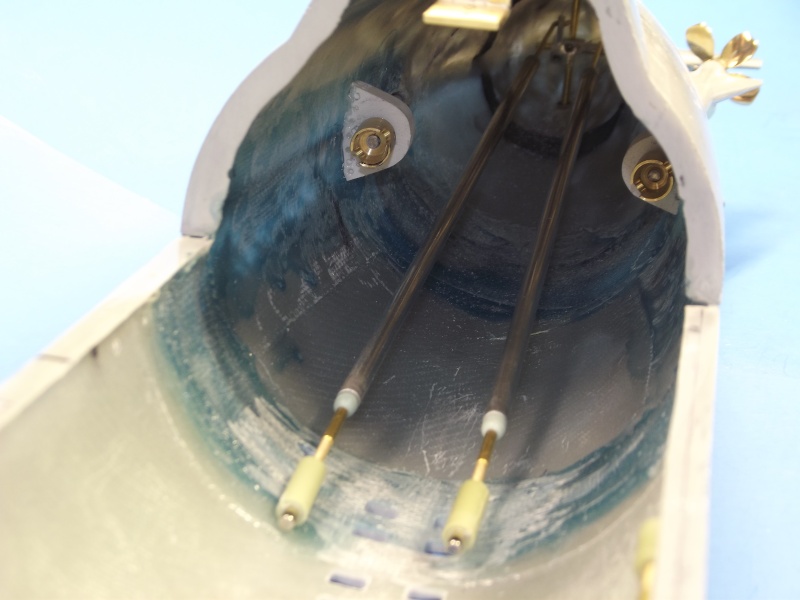
Looking aft into the hull we see the CA secured astern thrust blocks. Each propeller shafts forward end passes through the astern thrust bearing set within its thrust block. Once installed, the after face of a Dumas type universal coupler presses against a thrust washer which makes contact with the forward face of the astern Oilite bearing. This is where astern loads are presented by the propeller shaft when going astern.
Keep in mind that there are three bearings per shaft:
1. the ahead thrust bearing at the after end of the stern tube, against which the propeller hub (through a thrust washer) pushes
2. an intermediate journal bearing set at the extreme forward end of the stern tube, to damp out side loads (vibration) the shaft might experience at high RPM's
3. the astern thrust bearing housed within a bearing block which in turn is bonded to the hull
If you look real hard you can just make out the control surface operating shafts and the pushrod bell-cranks that make up to them. In this shot you get an appreciation how easy it is to make up stern control surfaces with a boat that makes use of two, rather than one, propellers.
Center, near the top of the hull are the rudder and stern plane pushrods. At the extreme forward ends are magnetic couplers which make up to their counterparts that run from the after end of the SubDriver, the SD pushrods passing through watertight seals and on into the cylinder were each makes up to a servo.
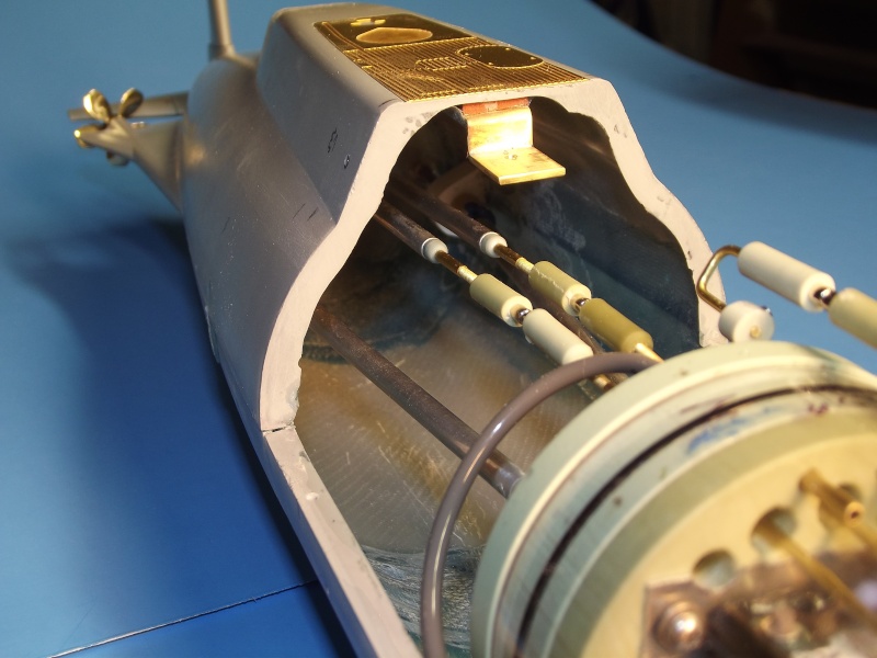
The magnet of each magnetic coupler makes a press-fit within a resin foundation that, in turn, accepts a threaded rod bonded to its pushrod -- turning the magnet foundation permits fine adjustment of pushrod length.
Between the propeller shafts and the SD motor shafts are intermediate drive shafts. These make up at each end in Dumas type universal couplers. These shafts transmit only torque, no axial loads, so no connectors are needed -- the intermediate drive shafts simply slide into place as the SD is installed within the hull.
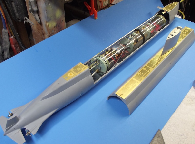
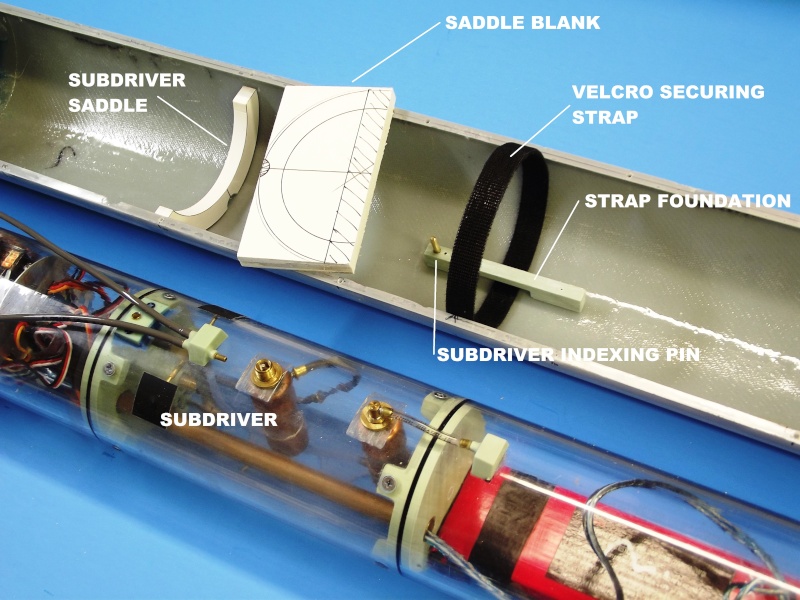
This is how the SD integrates within the hull. The SD indexes with the hull through a single brass pin set within the Velcro strap foundation -- this pin, which engages a hole in the bottom of the central ballast tank -- prevents axial and lateral motion of the SD once in place. You can make out the black Velcro strap that securely holds the SD down on the two saddles . The saddles position the cylindrical SD to that its longitudinal centerline falls shares that of the hull.
The removable SD can be installed/removed in seconds. The interface between the hull and SD propulsion, ballast, and control sub-systems are the two propulsion intermediate drive shafts, three magnetically coupled control surface pushrods, and the flexible hose that runs from atop the SD to the sail located snorkel induction mechanism.
A closer look at the saddles and Velcro strap that index and hold the SD within the hull. The strap foundation came from one of the submarine plastic kit r/c conversion fittings kits I produce. The two saddles were cut from laminations of PVC sheet, layered to a thickness of 3/8". The strap foundation was secured with two 2-56 machine screws. The saddles were CA'ed in place after establishing where the bottom flood-drain holes went - I didn't want the saddles to straddle open holes, so I waited till that work was done before determining exactly where in the hull the saddles would go.
Plotting and opening up the flood-drain holes will be covered in the next installment of this WIP.
Wait, wait............., where are the retractable front divingplanes????, you're going to drive her like this????
Manfred.
You observant so, and so! For the moment, yes. I'm in a rush to get this thing working in the water so I can freeze the design of the SD -- I need to know if the ballast tank is big enough to house the water displaced by the above waterline structures of the model. Once I do that, I make another SD for Andreas -- the originator of the kit. We worked a deal: I get the model, he gets a SD. Hence the rush on this. After I do that I'll retrofit a proper bow plane retract mechanism in this model.
A closer look at the saddles and Velcro strap that index and hold the SD within the hull. The strap foundation came from one of the submarine plastic kit r/c conversion fittings kits I produce.
I will steal that (and now I know the purpose of the small hole in de bottom of my ballast tank) you genius you.........will four hail maries and two our fathers in honor of your picture on my wall be sufficient? I will remove the darts arrows before I start.
The flat surface were the cylinders pass through the SD are also new in design?
Grtz,
Bart
My picture? The one with the front-and-center butt-cheeks?
No, I machined those flats to accommodate 2" type safety float-valves and emergency back-up bottles -- the 2"cylinders are 1/16" wall, but the 3" cylinder, used here, is 1/8" wall. Hence, the flats to clear enough thread to get the lock-down nuts to engage -- not standard: a smart looking fix covering up a stupid ****-up. A fix to correct poor planning. A specialty around here.
The flood and drain holes on the bottom of this NAUTILUS model are both an appealing scale feature and a vitally important element in the operation of this wet-hull type r/c submarine.
Through these openings water passes in and out of the hull as the SubDrivers (SD) ballast tank takes on and discharges water. And what better way than through the scale openings in the bottom of the hull? As the kit is primarily designed to be a dry-hull type, there is little in the instructions and no markings on the hull, indicating these flood-drain holes on the bottom of the hull -- it's left for the customer configuring the kit for wet-hull operation to determine the location, size and number of bottom flood-drain holes.
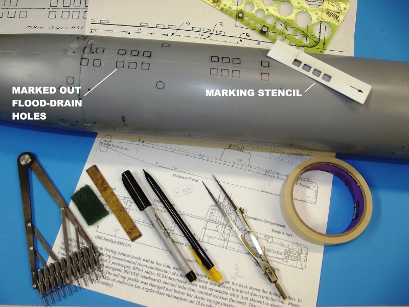
I identified drawings prepared by the much published (and authoratitive) Jim Christley That did a pretty good job of identifying the NAUTILUS flood-drain holes. I scaled his drawing up and used them to make a marking template.
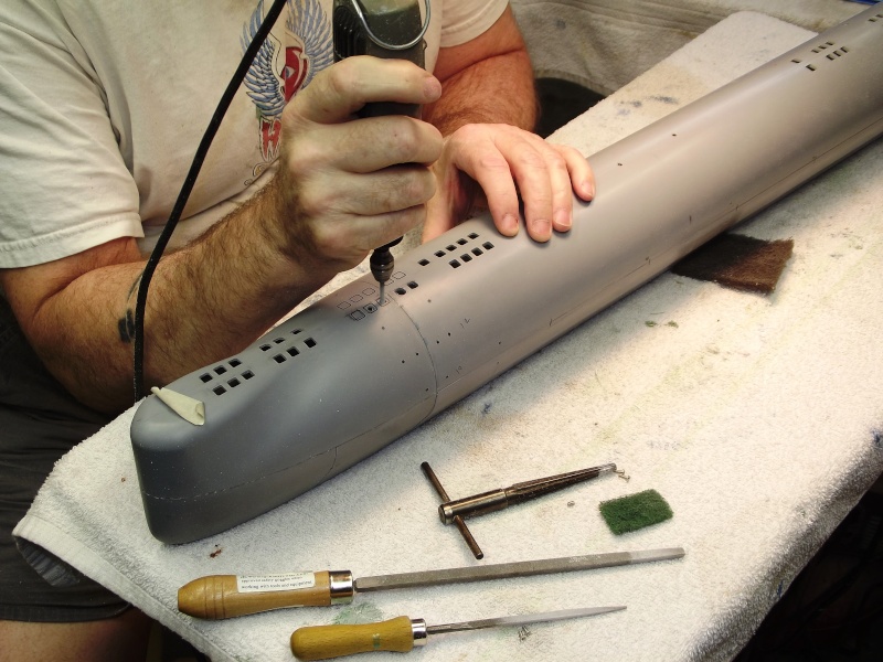
Marking the bottom of the hull the location and shape of the flood-drain holes is only part of the task. The GRP hull, essentially silicon glass fibers bound in a hard resin, requires proper tool selection and use to be cut and ground effectively.
The single removable water tight cylinder (WTC), or SubDriver (SD) as I call it, is aligned to the hull through a single indexing pin, and is held down onto two supporting saddles set at the bottom of the lower hull. I'll deomonstrate that interface in this installment of the WIP.
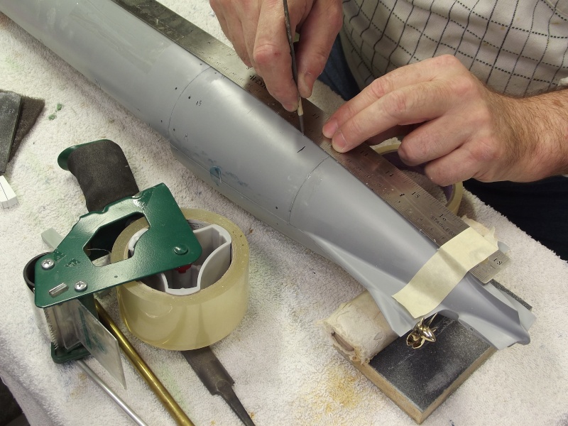
There was no molded-in place longitudinal cheat line at the bottom of the GRP hull pieces. No big deal, I determined the dead-center bottom with a piece of radially placed masking tape -- flopping it from being wrapped on one side, then the other and adjusting quarter-radius marks on the tape until I had a radius line on the tape of a length that worked each side of the hull. Using the marked tape as a measuring tool I placed two BDC points on the hull then scribed a longitudinal cheat line, connecting those two points, as illustrated in the above picture -- this engraving became the bottom hull longitudinal datum line off which I radially distanced the flood-drain and main sea water hole locations.
I found a Jim Christley illustration in one of my books that indicated credible locations and approximate lengths of the bottom flood-drain holes -- the ports through which seawater went in and out of the submarines ballast tanks. His drawing also indicated four other very important penetratons in the hull: the two sets of main sea water suctions and discharges.
Though there was no way to garner from this small and slightly smudged illustration the distance the flood-drain holes were from the bottom centerline, I made a best-guess using an old training-aid-book from my submarine days on the WEBSTER. Resolving those documents (and a 1/48 drawing left over from a RTR DeBoer Hulls NAUTILUS job done over a decade ago) to the 1/86 scale of the NAUTILUS model I'm currently assembling, I determined their shape and stand-off distance -- and from that I worked up a flood-drain hole marking stencil from plastic sheet.
A Draftsman's circle stencil was used to mark off the propulsion main sea water suctions and discharges -- one set on each side as the NAUTILUS' hull.
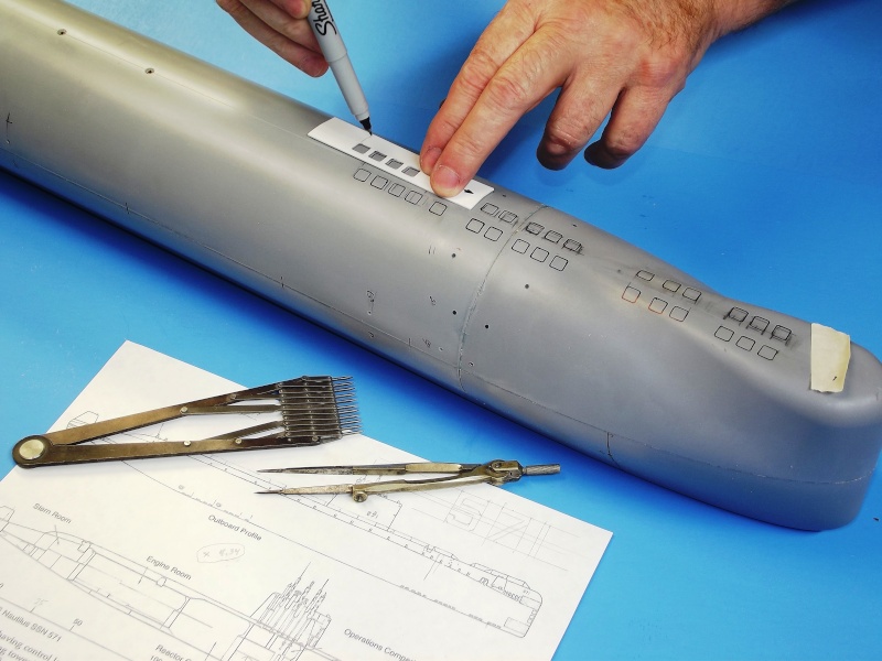
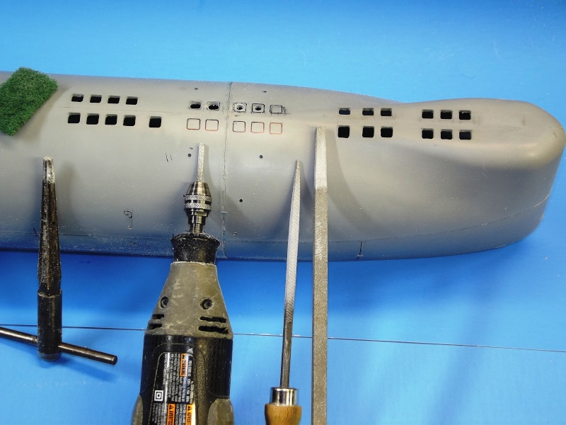
I worked out the ratio between the Christley drawings and the hull, applied that to a set of proportional dividers and lofted the flood-drain hole sizes and distances between centers to a .025" thick piece of polystyrene plastic sheet. The marked off holes then punched out with drill and files to produce a generic flood-hole marking tool. Here you see it put to work marking out some of the ballast tank flood-drain holes in the forward group.
The flood-drain holes were started with the carbide bit -- this tough, very hard coated tool makes quick work of hard substances such as glass. Glass is the 'G' in GRP.
I segregated all my cutting tools into three categories: those for plastic and brass alloys; those for iron and stainless-steel; and those tools condemned to cut GRP. How does a cutting tool get awarded the prestigious honor of chewing on glass? With use and age that tool has become a bit dull, its got one foot in the grave. So, its final use will be heroically grinding away GRP parts. That's how tough GRP is on tool-steel -- once that tool has tasted GRP, it's a gonner.
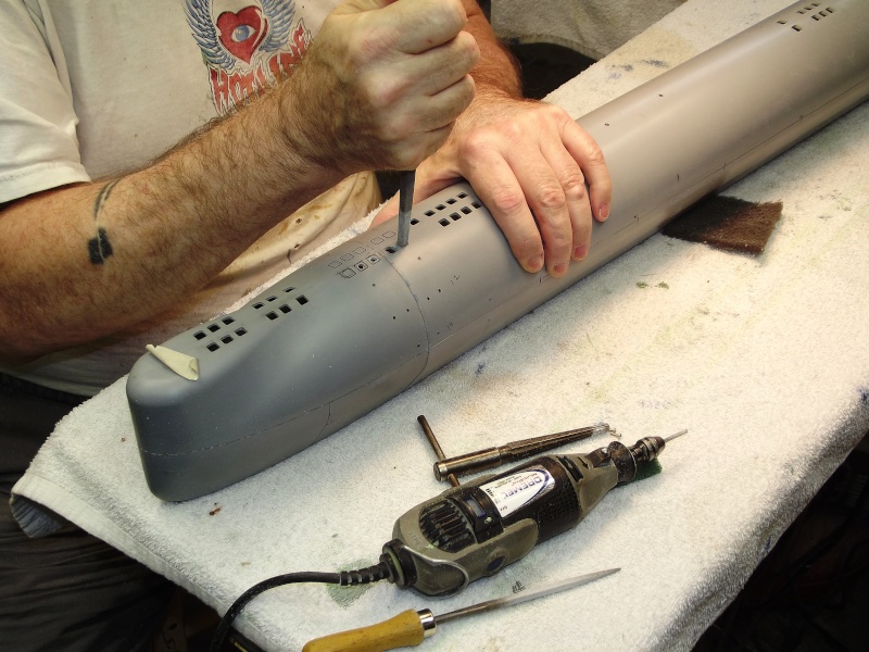
Over the decades I have assembled quit a collection of files of various shapes, cut, and sizes. here I've selected a square sectioned file to finish off opening the square holes -- holes initially punched out with a moto-tool carbide rasp. See those files? They'll be in a land-fill by this time next year.
The hand-reamer to the left was used to pen up the big circular main sea water openings near the stern. The moto-tool, equipped with a carbide rasp was used to make the initial opening for both circular and square holes; The two square sectioned files were used to give shape to the square holes.
From stencil manufacture, mark-out, to final hole trimming took me the better part of an afternoon. Knowing what tools to assign to the job and how to use them is the key to quick, clean work.
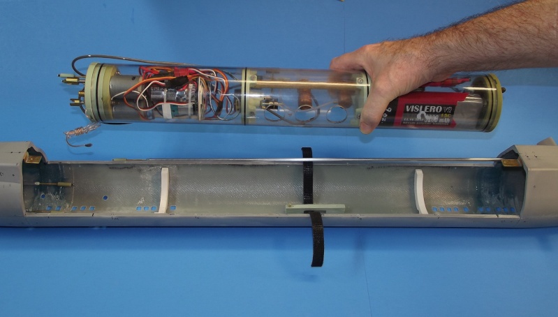
Holding the SD over the lower hull, illustrating the SD securing hardware in the lower hull that secures and indexes it once installed. The white items are the two CA'ed in place PVC plastic saddles. The foundation piece, that both retains the single securing strap, and supports the SD-to-hull indexing pin is in the center. The indexing pin engages a hole in the bottom of the SD's ballast tank, retaining it and keeping the SD from rolling or sliding once the Velcro strap is made up tight.
Demonstrating how the Velcro strap is employed to hold the SD down tightly onto the two mounting saddles. The bottom of the strap runs under and around the strap foundation pieces which in turn is secured to the bottom of the hull with machine screws. The double-sided Velcro (hooks on one side, hoops on the other) is slightly elastic permitting a very tight pull-down of the SD onto the saddles. The strap and the indexing pin makes the SD one with the hull, insuring no pushrod backlash or binding of the running gear.
The thin, very delicate acid-etched deck pieces might become an operational problem. My biggest fear is that some idiot, either launching or retrieving this model, will accidentally push his fat thumb through the very delicate, minimally supported, center acid-etched deck pieces.
To be fair, there are underlying supports for the central acid-etched deck pieces; Andreas has provided transverse GRP cross-bracing upon which portions of the acid-etched deck will sit. The issue is, I don't think there are enough of them -- a lot of flimsy deck remains unsupported.
It's my intention to double the number of below deck braces to give this thing a chance of getting through at least one season of operation without a damaged acid-etched deck!
Contributing to the center deck weakness problem is the incorporation of a trough in the top of the hull.
Why?
Keep in mind that this kit was originally designed as a dry-hull type r/c submarine. The trough was built in to reduce the boats total submerged displacement. Had the kits hull been capped at its deck level (which would have solidly supported the center portions of acid-etched deck) doing so would have resulted in a hull displacing much more water than had the trough been incorporated. More above waterline displacement means a larger ballast tank, and a larger ballast tank takes up more valuable volume within the hull, making installation, adjustment, and replacement of internal devices a Plumber's nightmare.
As it is now the acid-etched deck is divided into four pieces: The forward most piece sits flush at the bow with the entirety of the piece supported by the hull; same with the aftermost acid-etched piece. The center section, with the trough, has only a few narrow GRP transverse (cross-braces) to support the very flimsy and easily pushed in acid-etched deck. However, the acid-etched deck has narrow transverse solid areas where the actual submarine had these deck re-enforcing cross-braces -- I'll place additional GRP cross braces in the trough, under those solid areas, to add support to the deck pieces over the trough area.
David, you have the index pin for positioning the SD, but how about the endcaps of the SD, how do you make sure they are always in the same position when you close them?
Grtz,
Bart
Practical wisdom is only to be learned in the school of experience. "Samuel Smiles"


Comment