Akula 1/144 Scratch built

Collapse
X
 
  • Time
  • Show
Clear All
new posts
  • bwi 971
    Captain
    • Jan 2015
    • 902

    #16
    Air compressor / Casting aides

    I started this project only heaving a small lathe. As my surname isn't Rockefeller I have to come up with DIY stuff to controle the budget......AND THAT TAKES A LOT OF MY BUILDING TIME Grrrrr (at least 50%, make them so they will last forever).......BUT I LOVE DESIGNING THESE THINGS.

    As my workshop is in the basement of the house an regular compressor was not an option due to the noise it would create keeping the children awake. A fridge compressor is quite silent and can be used as an air compressor. It can also be used to create a vacuum what solves the issue of the vacuum chamber (they are capable to pressures up to 30bar/440psi......so treat them as you treat live ammunition).

    As air pressure is quite dangerous and I wanted everything to be safe and sound I went to several specialized companies for advice and parts needed. As a pressure vessel I opted for an old 5kg CO2 fire extinguisher in aluminum, work pressure is 50bar which will be more than sufficient, the extinguisher was resent pressure tested (hydro tested). I got it for free from a service company. The fridge compressor itself was also a gift from an AC service company (new in the box). It took me a few weeks to find these items, but it was worth wile as all was donated to me free from charge. Next I purchased all the other stuff, pressure switch with relieve valve, non-return valve, pressure reducer, pressure sensor, temperature sensor, safety valve, various couplings,...., in a specialized store, they advised me what parts to use (working pressure, design pressure, safety systems, etc...).

    Click image for larger version

Name:	silent air compressor DIY (5).jpg
Views:	1
Size:	96.0 KB
ID:	98369

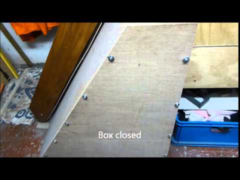
    I made an box out of shuttering plywood to contain the pressure vessel, on top I placed the compressor and all the regulating stuff, everything was connected together. The test was perfect the unit is makes no noise just the noise you hear on a fridge. I set the unit to stop at 5 bar and re-starts at 4 bar. To give a personal touch I milled some sub class names in the shuttering plywood on one side. On the other side I milled the names of the companies in the shuttering plywood, who helped me out supplying the extinguisher and fridge compressor for free. That is the least I could do ( sent a picture of it to them).

    Click image for larger version

Name:	silent air compressor DIY (2).jpg
Views:	1
Size:	90.0 KB
ID:	98370

    Click image for larger version

Name:	silent air compressor DIY (4).jpg
Views:	1
Size:	92.0 KB
ID:	98371

    Click image for larger version

Name:	silent air compressor DIY (6).jpg
Views:	1
Size:	57.9 KB
ID:	98374

    The vacuum tank was made out of thick PVC the lid was made of Plexiglas so I could Cleary see the what is going on when degassing. The seal is an O-ring. The dimensions of the groove were calculated as per Andrew Lawrence directions I found on another forum. Here is the link to the youtube video https://www.youtube.com/watch?v=hWcryehE7EU#t=342.

    The vacuum tank is combined with my compressor meaning that I can deviate the suction of the compressor to the tank and create a vacuum that is sufficient to degassing the silicone mold casting resin.

    Click image for larger version

Name:	silent air compressor DIY (1).jpg
Views:	1
Size:	90.2 KB
ID:	98372

    Click image for larger version

Name:	silent air compressor DIY (9).jpg
Views:	1
Size:	93.4 KB
ID:	98373

    The pressure pot for casting I purchased at the www it’s a regular paint pressure tank of 2,25 Gallon/8.5 liter which I modified a little bit.

    Click image for larger version

Name:	silent air compressor DIY (8).jpg
Views:	1
Size:	89.5 KB
ID:	98375

    Mission accomplished
    Practical wisdom is only to be learned in the school of experience.
    "Samuel Smiles"

    Comment

    • He Who Shall Not Be Named
      Moderator
      • Aug 2008
      • 12313

      #17
      Very, very nice work, Bart!

      You might want to couple the compressor suction to a volume tank (one of those cheap road-side air-tanks used to inflate tires, available from Harbor Freight) through a T-valve.

      When you start using vacuum to get all the resin into a complicated tools cavities (and believe me, the rate you're going, you WILL!) you don't have time for the low volume compressor to evacuate the air from your pot -- you want that vacuum ... NOW! or the resin will cure before you can de-air it. Hence, the use of a pre evacuated volume tank.

      Click image for larger version

Name:	DSCN0025.jpg
Views:	1
Size:	91.9 KB
ID:	98377 Click image for larger version

Name:	DSCF7449.jpg
Views:	2
Size:	91.2 KB
ID:	98378 Click image for larger version

Name:	013.jpg
Views:	2
Size:	94.5 KB
ID:	98379 Click image for larger version

Name:	006.jpg
Views:	3
Size:	86.5 KB
ID:	98380 Like these.

      You, sir, are a Craftsman -- you put as much care with your tools as you do your work.

      It's official now, I hate you.

      M
      Last edited by He Who Shall Not Be Named; 05-01-2015, 07:07 AM.
      Who is John Galt?

      Comment

      • bassplayer1
        Lieutenant Commander
        • Mar 2010
        • 244

        #18
        Originally posted by bwi 971

        Thks Yannis.....I will be knocking on your door for sure when I start with the my Delta VI..... I learn by watching your skills sir.

        grtz,
        Bart

        Any time Bart, it will be a plesure !!!

        Comment

        • bwi 971
          Captain
          • Jan 2015
          • 902

          #19
          Silencer and cyclone

          Hear some of you say “50% of the building time” Yeah right…….I will prove it with my dust collection system.

          Here again some caution notes:
          Please note that building an silencer yourself is at your own risk, I do not recommend this to do it yourself. A vacuum cleaner is a heat source and placed in an confined space is a potential fire hazard. I made calculations to get the optimized airflow, if you get it wrong everything will heatup and start a fire.I safeguard the air temperature at the silencer outlet, if thing overheat everything shuts down.

          And as we speak of fire hazards I have a smoke detector and extinguisher in my basement/workshop, just think about the value of all bits and pieces we have......it's worth the money.

          Remember the dust problem when I made my masters. Didn’t want to go through that again, (took me a lot of flowers to make up for that one with my beloved wife) so I bought myself a small compact bagless vacuum cleaner that I can connect to all the machinery. Again I could not use it in the evening that thing kept everybody awake in the late hours. So I developed the “thing”…… some of you might have noticed it before.

          Click image for larger version

Name:	Akula (78).jpg
Views:	276
Size:	68.6 KB
ID:	98382

          The “thing” my hull is hanging on is the silencer for the vacuum cleaner. Awkward chape?
          The only available space left (except the ceiling) in my basement was a triangle underneath the stairs, so I improvised, adapted and overcame.

          It is a box with a labyrinth inside were my vacuum cleaner is placed in. At the end of the labyrinth an opening is provided to let the air of the vacuum cleaner out (it has to be big enough so there is no pressure or temperature builtup. The labyrinth is supported by tree treated rods. All faces are tiled with Acoustic Panels. Pictures will explain.

          Click image for larger version

Name:	Dust collection (1b) (Custom).jpg
Views:	242
Size:	91.2 KB
ID:	98383 Click image for larger version

Name:	Dust collection (2b) (Custom).jpg
Views:	282
Size:	92.9 KB
ID:	98384 Click image for larger version

Name:	Dust collection (3b) (Custom).jpg
Views:	242
Size:	93.7 KB
ID:	98385 Click image for larger version

Name:	Dust collection (4b) (Custom).jpg
Views:	235
Size:	92.7 KB
ID:	98386 Click image for larger version

Name:	Dust collection (5b) (Custom).jpg
Views:	249
Size:	94.3 KB
ID:	98387 Click image for larger version

Name:	Dust collection (6b) (Custom).jpg
Views:	250
Size:	92.7 KB
ID:	98388

          And it does work!

          .

          That was it?...... NO IT WASN’T…..bagless is great……but opening the box every hour because the filter of the vacuum cleaner is clogged IS VERY ENNOYING.
          I dit a WWW search for a decent primary filter……seems cyclone filters are used often in the woodworker business. Could it be DIY’ed?

          Yes, I stumbled upon the site of William Pentz, it is a commercial site but if you look heard enough you can find plans……I give you the shortcut: http://billpentz.com/woodworking/cyc...clone_plan.cfm. There is even a calculation sheet provided with an drawing…..can one ask for more.

          It is straight forward….I made mine out of styrene sheet…..the only thing I have adapted was that I worked with flanges and threated rods to connect all parts together. The hardest part is the making of the cone more specific the clueing.

          You can make the cone as long as you wish……the longer the better separation you get.
          I dimentioned mine in such way that everything fits under the staircase, behind the silencer.

          How does it work…..dirty air is sucked in to the cyclone by the vacuum cleaner……The mix of air and dirt particles are forced into a spin by an helix in the cyclone chamber. This causes the heavier particles to go to the wall of the drop cone where they will eventually drop death into the collector bucket. Clean air is sucked out in the middle were the dirt partials can’t come due to the centripetal force caused by the spinning.

          Click image for larger version

Name:	Dust collection (15b) (Custom).jpg
Views:	247
Size:	89.5 KB
ID:	98389 Click image for larger version

Name:	Dust collection (9b) (Custom).jpg
Views:	231
Size:	90.0 KB
ID:	98390 Click image for larger version

Name:	Dust collection (10) (Custom).jpg
Views:	223
Size:	72.5 KB
ID:	98391 Click image for larger version

Name:	Dust collection (11b) (Custom).jpg
Views:	239
Size:	95.7 KB
ID:	98392 Click image for larger version

Name:	Dust collection (12b) (Custom).jpg
Views:	239
Size:	47.8 KB
ID:	98393 Click image for larger version

Name:	Dust collection (13b) (Custom).jpg
Views:	222
Size:	63.2 KB
ID:	98394 Click image for larger version

Name:	Dust collection (14b) (Custom).jpg
Views:	239
Size:	65.3 KB
ID:	98395

          It works great I only have to empty the bucket once in a while, it catches 99% of the dust even the smallest particles and the Vacuum cleaner stays clean for a looooong time. In practice I clean it when I empty the collector bucket of the cyclone (two times last year).

          But I also guard the air temperature at the silencer outlet, this gives me an indication if things get out of hand inside or not (overheating) better safe than sorrow.

          grtz,
          Bart
          Last edited by bwi 971; 07-30-2015, 03:51 PM.
          Practical wisdom is only to be learned in the school of experience.
          "Samuel Smiles"

          Comment

          • bwi 971
            Captain
            • Jan 2015
            • 902

            #20
            Originally posted by He Who Shall Not Be Named
            Very, very nice work, Bart!

            You might want to couple the compressor suction to a volume tank (one of those cheap road-side air-tanks used to inflate tires, available from Harbor Freight) through a T-valve.

            When you start using vacuum to get all the resin into a complicated tools cavities (and believe me, the rate you're going, you WILL!) you don't have time for the low volume compressor to evacuate the air from your pot -- you want that vacuum ... NOW! or the resin will cure before you can de-air it. Hence, the use of a pre evacuated volume tank.

            [ATTACH=CONFIG]31157[/ATTACH] [ATTACH=CONFIG]31158[/ATTACH] [ATTACH=CONFIG]31159[/ATTACH] [ATTACH=CONFIG]31160[/ATTACH] Like these.

            You, sir, are a Craftsman -- you put as much care with your tools as you do your work.

            It's official now, I hate you.

            M
            And you sir.......you give me headaches LOL.
            Every time I sit back and relax, enjoying my life, no worries at all…… you're making me nuts with new stuff (at least for me it is new).

            So resin outside the vacuum chamber, tool inside and the resin is sucked into the tool by the differential pressure?

            grtz,
            Bart
            Practical wisdom is only to be learned in the school of experience.
            "Samuel Smiles"

            Comment

            • He Who Shall Not Be Named
              Moderator
              • Aug 2008
              • 12313

              #21
              Originally posted by bwi 971
              And you sir.......you give me headaches LOL.
              Every time I sit back and relax, enjoying my life, no worries at all…… you're making me nuts with new stuff (at least for me it is new).
              So resin outside the vacuum chamber, tool inside and the resin is sucked into the tool by the differential pressure?

              grtz,
              Bart
              Yeah ... no rest for the weary. Like you and the other thoughtful modelers who post, when we see someone tip-toeing down the path we know all too well, and see a land-mine they may not be aware of, we work quickly to give them a heads up.

              Right now, your compressor/vacuum machine will do the things you want. I'm telling you that soon you will be presented with a casting job that will demand at least a slight vacuum assist to fill the tool cavities -- and that process has to be quick! Quicker than the CFM capability of that high pressure/vacuum, low CFM compressor you have. Thus, the need to 'store' your vacuum for quick evacuation of a resin casting tool.

              I issue this 'warning' only because you are a quickly rising star in this game: your work is of a high standard, and you exhibit all the characteristics of an excellent model builder. You are fearless. Vacuum assisted casting is in your immediate future. Don't fight it. You are doomed.

              Pick up a cheapie volume tank and three-way valve.

              There ... that will be 20-buck. I'll be here all week.

              M
              Who is John Galt?

              Comment

              • bwi 971
                Captain
                • Jan 2015
                • 902

                #22
                Intake Scoop & SOKS

                The water intake scoop I have drawn up myself from pictures found on the web and in the book of Wayne Frey. They have been made out of two pieces of acrylate and grinded/sanded into shape.
                The scoop I initially made was oversized so I narrowed everything down. The inlet was opened up with a handheld grinder.

                Click image for larger version

Name:	Akula (152).jpg
Views:	1
Size:	77.5 KB
ID:	98437Click image for larger version

Name:	Akula (153).jpg
Views:	1
Size:	64.5 KB
ID:	98436

                I will take care of the markings in the P&S (paint and sand) process

                Next up were the SOKS (Systema Obnaruzheniya Kil'vaternogo Sleda)....yep did my homework pa.......sensors, these I have crafted without any drawings just by means of pictures and some guested dimensions. See pictures below.

                Click image for larger version

Name:	Akula (5).jpg
Views:	1
Size:	65.8 KB
ID:	98438Click image for larger version

Name:	Akula (6).jpg
Views:	1
Size:	35.9 KB
ID:	98439

                Those were fabricated in the early days of the project, still have to do the cover on the left one and change the order of the sensors (top and bottom), see pic below.

                Click image for larger version

Name:	akula (60).jpg
Views:	1
Size:	87.1 KB
ID:	98440Click image for larger version

Name:	akula (60b).jpg
Views:	1
Size:	70.4 KB
ID:	98441

                As was preparing for molding, some other part needed fabrication. The hatch of the communication buoy is fitted with cable protectors.

                Click image for larger version

Name:	Akula (171).jpg
Views:	1
Size:	57.2 KB
ID:	98442

                The difficult part was the symmetry between PS and SB protection.
                I started tag-gluing to pieces of 3mm acrylate sheet. Then drew the longitudinal outline on it and grinded it into shape.

                Click image for larger version

Name:	Akula (159).jpg
Views:	1
Size:	71.3 KB
ID:	98443Click image for larger version

Name:	Akula (160).jpg
Views:	1
Size:	85.4 KB
ID:	98444Click image for larger version

Name:	Akula (161).jpg
Views:	1
Size:	91.3 KB
ID:	98445

                Next was the cross section this was also grinded in shape, togeter with my fingernails…..this stuff is small.

                Click image for larger version

Name:	Akula (162).jpg
Views:	1
Size:	93.0 KB
ID:	98446Click image for larger version

Name:	Akula (163).jpg
Views:	1
Size:	82.9 KB
ID:	98447Click image for larger version

Name:	Akula (164).jpg
Views:	1
Size:	91.4 KB
ID:	98448

                The parts were separated resulting in 2 symmetrical protections

                Click image for larger version

Name:	Akula (165).jpg
Views:	1
Size:	86.8 KB
ID:	98449Click image for larger version

Name:	Akula (166).jpg
Views:	1
Size:	90.9 KB
ID:	98450

                The Fwd escape hatch was also fabricated, I had a picture as an example.

                Click image for larger version

Name:	Akula (170).jpg
Views:	1
Size:	96.7 KB
ID:	98451

                The dome was made out of 3mm acrylate, the diameter is 13mm.

                Click image for larger version

Name:	Akula (157).jpg
Views:	1
Size:	77.9 KB
ID:	98452

                Groves will be taken care off during the P&S process.
                I will cast all the above stuff in an later stadia of the project.
                Practical wisdom is only to be learned in the school of experience.
                "Samuel Smiles"

                Comment

                • He Who Shall Not Be Named
                  Moderator
                  • Aug 2008
                  • 12313

                  #23
                  Great looking stuff here, Bart.

                  Yes ... I tell everyone else not to make pointless, gushing posts. But, I'm special!

                  M
                  Who is John Galt?

                  Comment

                  • bwi 971
                    Captain
                    • Jan 2015
                    • 902

                    #24
                    Rudders, Planes & Towed array pot

                    In between I started with the rudders and dive planes. I have made them out of rectangular pieces of oak (what renovating a house is good for). Glued some copies of the drawing on top and started sanding and grinding till I had the wanted shape. The Same I did with the housing of the towed array. Then applied some putty, filler and consequently some sanding & grinding.
                    After casting I will cut-out the actual surfaces of the rudders and planes. I will make the surfaces as large as possible especially the ones of the rudders in order to get a good turning rate of the sub.

                    Click image for larger version

Name:	Akula (4).jpg
Views:	1
Size:	97.6 KB
ID:	98488

                    When I took the planes, rudders and pod and presented them to the hull they seemed out of scale. I remembered that I drew them myself taking pictures as a reference as the shapes of the parts on the Greg Sharpe drawing differed from the pictures. Now they look to big. I shortened (halve an inch) and narrowed them down (1/4 inch) to match the scale.

                    As the silicone is quite expensive I did not want to waste it in oversize boxes so I tailor-made some boxes out of styrene. The dimensions are slightly larger than the dimensions of the part to cast. The top of the lower part of the box is also the dividing line of the part. It makes it easier to remove the modeling clay excess when you press the part in it. The boxes are provided with two holes for respectively the vent and pouring channel. The lid slides over the lower part.

                    Click image for larger version

Name:	Akula (107).jpg
Views:	1
Size:	53.2 KB
ID:	98453 Click image for larger version

Name:	Akula (108).jpg
Views:	1
Size:	52.9 KB
ID:	98454 Click image for larger version

Name:	Akula (109).jpg
Views:	1
Size:	56.9 KB
ID:	98455 Click image for larger version

Name:	Akula (110).jpg
Views:	1
Size:	76.8 KB
ID:	98456 Click image for larger version

Name:	Akula (111).jpg
Views:	1
Size:	78.5 KB
ID:	98457

                    For the rudder and dive planes this will be an intermediate casting. I have made both out of oak and I felt not comfortable to saw the control surface out of the masters, I was afraid the trailing edges would brake (they are quite thin). So I first make a cast out of the masters and then saw the control faces out of the cast (if I screwed up I only had to cast a new one). Afterwards I will make another cast of the finished pieces. The water intake scoop and the towed area pod will be cast directly into a finished product.

                    A drill press was missing on my machinery list, and this was an item I needed for manufacturing the rudders and diveplanes. I did not need a big machine but I wanted one with high precision. After streaming the WWW I found one for my budget I wanted to spent with a max clearance of 0.02mm on the spindle.

                    The masters of the rudders end dive planes were still were I left them…sitting in the modeling clay. For the making of the sprue channels I modified a syringe so I got the desired diameter for the channels. Filled the syringe with molding clay an out came the channel. I cut the cylindrical formed clay in half longitudinally and pressed them in place on the mold. The mold were closed and the seams were sealed with modeling clay. The poor funnels I made out of paper, put in place and sealed with molding clay.

                    Click image for larger version

Name:	Akula (114).jpg
Views:	1
Size:	53.6 KB
ID:	98458 Click image for larger version

Name:	Akula (115).jpg
Views:	1
Size:	48.8 KB
ID:	98459 Click image for larger version

Name:	Akula (116).jpg
Views:	1
Size:	47.2 KB
ID:	98460

                    The silicone was degassed in my DYI vacuum chamber (works Great!) and poured into the molds. After curing molds were opened up and master and moulding clay was removed. The only thing I needed to do before pouring the other half is making new sprue channels in modeling clay and put them in place together with the masters……and apply release agent. Closed and sealed everything and poured the other halve. The mold worked out fine.

                    Click image for larger version

Name:	Akula (117).jpg
Views:	1
Size:	62.8 KB
ID:	98461 Click image for larger version

Name:	Akula (120).jpg
Views:	1
Size:	64.9 KB
ID:	98462

                    Next step was to pour the resin in the molds, again I made the pour funnels out of paper. After the molds were filled I placed the in my pressure chamber @ 3bar, and let them cure overnight. I was very pleased with the result. The only thing I noticed is that the diving plane was slightly bent but the master was straight. I thought I applied to much force when I pressed the master in the modeling clay as the rudder is long and thin it is fragile. Later I discovered that the rudder didn’t fit into the mold anymore. So the mold was OK the deformation happened when I removed the dive plane from the mold. It seems that the resin was not completely hardened. So a casted another one, left it for three days in the presser chamber and came out perfectly.

                    Click image for larger version

Name:	Akula (123).jpg
Views:	1
Size:	72.2 KB
ID:	98463 Click image for larger version

Name:	Akula (124).jpg
Views:	1
Size:	61.8 KB
ID:	98464 Click image for larger version

Name:	Akula (126).jpg
Views:	1
Size:	79.3 KB
ID:	98465

                    Next step was to cut the control faces out. Everything was marked in pencil. On the real sub all the rudders and diving planes are provided with trim surfaces these are supported by pintle bearings. I want to integrate these bearing in the model. So these were also drawn.

                    First I had to drill the rudderstock holes (drill press time). As the rudders and dive planes are double curved it is hard to clamp them in a machine vice without a sort of jig. As I had a lazy day I din’t want to make a jig, so I tried……….modeling clay. This works great, just put an piece of modeling clay on both sided and clamp it in the machine vice, the modeling clay squeezes itself in place wen pressure is applied. 2mm holes were drilled.

                    Click image for larger version

Name:	Akula (133).jpg
Views:	1
Size:	76.5 KB
ID:	98466 Click image for larger version

Name:	Akula (134).jpg
Views:	1
Size:	60.4 KB
ID:	98467

                    The surfaces were cut out with a scroll saw. Before I made the cut I had to level the planes in both directions in order to get a nice vertical cut. This was done with modeling clay. A recess for the pintel bearing was also cut in the control surface. All cut surface were sanded. A radius was sanded on the leading edge of the control surface. The pintle bearings (3x5x5mm) were made out of a 3mm styrene sheet glued in place and provided with a 2mm hole.

                    Click image for larger version

Name:	Akula (135).jpg
Views:	1
Size:	79.2 KB
ID:	98468

                    The gaps between the control surface and the actual plane were filed up with putty but not before I thickened up the leading edge of the control surfaces by masking tape (4 layers approx. 0,5mm) and applied some release agent so the putty will not bond with the tape. After curing all were sanded in shape resulting in a nice small 0,5mm gap. The upper and lower gap between the control surface and plane needed also attention. Putty was applied on top and bottom and after curing sanded in shape resulting in a nice small gap. (Idea stolen from his Eminence)

                    Click image for larger version

Name:	Akula (128).jpg
Views:	1
Size:	94.4 KB
ID:	98469 Click image for larger version

Name:	Akula (137).jpg
Views:	1
Size:	65.1 KB
ID:	98470 Click image for larger version

Name:	Akula (138).jpg
Views:	1
Size:	90.1 KB
ID:	98471 Click image for larger version

Name:	Akula (132).jpg
Views:	1
Size:	75.6 KB
ID:	98472 Click image for larger version

Name:	Akula (140).jpg
Views:	1
Size:	93.1 KB
ID:	98473


                    Bushings will support the rudderstock, I made them out of a 3mm brass rod, the all received a 2mm hole.
                    · 4pc for the pintle bearings (rudderstock runs through it) Ø3x3mm
                    · 4pc for the upper bearing (protrusion of the hull) Ø3x10mm
                    · 3pc for the lower bearing Ø3x3mm
                    These bushings will be placed in position in the molds prior to the casting process so they will be imbedded in the parts after casting.

                    Click image for larger version

Name:	Akula (142).jpg
Views:	1
Size:	93.4 KB
ID:	98474

                    Next step was to lineup the rudders and planes to the hull and adapt the roots to the hull for a perfect fit. A release agent was applied on the hull iwo the planes location; putty was used to make the curved transition between the hull and planes.

                    Click image for larger version

Name:	Akula (149).jpg
Views:	1
Size:	86.2 KB
ID:	98475 Click image for larger version

Name:	Akula (150).jpg
Views:	1
Size:	44.5 KB
ID:	98476 Click image for larger version

Name:	Akula (151).jpg
Views:	1
Size:	77.9 KB
ID:	98477

                    P&S ongoing

                    Click image for larger version

Name:	Akula (155).jpg
Views:	1
Size:	91.2 KB
ID:	98478

                    I managed to spray and sand the parts several times and their ready for molding.

                    Initially I didn’t wanted to make use of the Fwd planes, but along the way I have decided to use them for depth control. So I had to fabricate them, they will be fixed not retractable. As above mentioned I first chapped my rudders and planes an afterwards, when I drilled the holes for the rudderstock. It was not so evident to get the hole nicely in the centerline.

                    So I decided to drill the hole of the rudderstock first and then shape the Fwd plane.

                    I started with two pieces of 3mm of acrylate sheet, cut at the right dimensions and clued together. Then I draw the longitudinal section a a piece of paper, inclusive the position of the hole for the rudderstock, and glued it on the workpiece.

                    Click image for larger version

Name:	Akula (172).jpg
Views:	1
Size:	70.5 KB
ID:	98479

                    The workpiece was clamped into the machine vice an de 2mm hole was drilled, as the shape was rectangular and flat it was a piece of cake to drill the hole in the centerline. Next the piece was cut to the longitudinal outlines.

                    Click image for larger version

Name:	Akula (173).jpg
Views:	1
Size:	69.6 KB
ID:	98480 Click image for larger version

Name:	Akula (174).jpg
Views:	1
Size:	43.0 KB
ID:	98481

                    Then I drew the cross-sections of the plane on paper and clued them to the workpiece, and grinded/sanded into shape.

                    Click image for larger version

Name:	Akula (175).jpg
Views:	1
Size:	59.7 KB
ID:	98482 Click image for larger version

Name:	Akula (176).jpg
Views:	1
Size:	63.9 KB
ID:	98483 Click image for larger version

Name:	Akula (178).jpg
Views:	1
Size:	92.2 KB
ID:	98484 Click image for larger version

Name:	Akula (179).jpg
Views:	1
Size:	57.2 KB
ID:	98485 Click image for larger version

Name:	Akula (181).jpg
Views:	1
Size:	89.4 KB
ID:	98486

                    Ready to go

                    Click image for larger version

Name:	Akula (183).jpg
Views:	1
Size:	65.8 KB
ID:	98487
                    Practical wisdom is only to be learned in the school of experience.
                    "Samuel Smiles"

                    Comment

                    • greenman407
                      Admiral
                      • Feb 2009
                      • 7530

                      #25
                      This might be pointless.......but this guy is good. OOOPPPSSS!
                      IT TAKES GREAT INTELLIGENCE TO FAKE SUCH STUPIDITY!

                      Comment

                      • bwi 971
                        Captain
                        • Jan 2015
                        • 902

                        #26
                        maybe pointless ..........but well appreciated!
                        Practical wisdom is only to be learned in the school of experience.
                        "Samuel Smiles"

                        Comment

                        • He Who Shall Not Be Named
                          Moderator
                          • Aug 2008
                          • 12313

                          #27
                          (you caught the Dragon sleeping, Mark)

                          Bart is kicking some serious donkie here. Nice work, Bart!

                          M
                          Who is John Galt?

                          Comment

                          • bwi 971
                            Captain
                            • Jan 2015
                            • 902

                            #28
                            Originally posted by He Who Shall Not Be Named
                            (you caught the Dragon sleeping, Mark)

                            Bart is kicking some serious donkie here. Nice work, Bart!

                            M
                            I will suck up all your compliments with eager sir as they will protect me for the wrath of the dragon when it wakes up.

                            Grtz,
                            Bart
                            Practical wisdom is only to be learned in the school of experience.
                            "Samuel Smiles"

                            Comment

                            • bwi 971
                              Captain
                              • Jan 2015
                              • 902

                              #29
                              I postponed this one for a long time, kept pushing it fwd. But I have to do it sooner or later.
                              I never have done this but there were plenty things I had never done before this build with fail and error.

                              In preparation to the scribing I have to draw every single hatch, hole,….onto the hull. I have seen this done by his eminence back then, he made some kind of jig that holds the boat and it enables it to turn around freely, it works like a lathe.

                              Making all these jigs is time consuming so when I do it I use good solid materials so I can reuse them for later projects.

                              The molding board that I made previous was used as the base structure. On top two post were placed. The post have some horizontal travel so the hull can be placed in-between, this was managed with a slotted baseplate. I have designed the base of the post in such way that they do not protrude the perpendiculars of the hull, else the would get in the way when drawing.

                              Click image for larger version

Name:	Akula (199).jpg
Views:	1
Size:	64.0 KB
ID:	98521

                              The sterntube is used to connect the stern to the aft post by means of a 4mm diameter shaft, the aft post is provided with a bushing (inner diameter 4mm outer 8mm with collar).

                              Click image for larger version

Name:	Akula (200).jpg
Views:	1
Size:	59.9 KB
ID:	98522

                              As I didn’t(t want to drill a hole in the bow I came up with a hollow disk that would take the curved bow. I provided the disk with an o-ring in order to get enough friction between the disk and the bow. The disk is also be provided with a bushing, and same goes for the Fwd post. A dia 4mm rod is connecting the disk with the post.

                              Click image for larger version

Name:	Akula (185).jpg
Views:	1
Size:	80.1 KB
ID:	98523 Click image for larger version

Name:	Akula (187).jpg
Views:	1
Size:	39.1 KB
ID:	98524 Click image for larger version

Name:	Akula (189).jpg
Views:	1
Size:	36.6 KB
ID:	98525 Click image for larger version

Name:	Akula (190).jpg
Views:	1
Size:	73.2 KB
ID:	98526

                              All the a.m. parts were fabricated and installed to the molding board. The hull was presented to the jig and it turned out very well, no hiccups.

                              In order to get a nice perpendicular movement from the marker with the hull I also fabricated a movable guide that can be tighten to the base (moulding board).

                              Click image for larger version

Name:	Akula (191).jpg
Views:	1
Size:	73.1 KB
ID:	98527

                              As I finished that I also made the post that retained the marker, the post is also provided with slots for the up and down movement.

                              Click image for larger version

Name:	Akula (195).jpg
Views:	1
Size:	68.4 KB
ID:	98528 Click image for larger version

Name:	Akula (194).jpg
Views:	1
Size:	73.6 KB
ID:	98529 Click image for larger version

Name:	Akula (196).jpg
Views:	1
Size:	42.7 KB
ID:	98530 Click image for larger version

Name:	Akula (197).jpg
Views:	1
Size:	41.9 KB
ID:	98531 Click image for larger version

Name:	Akula (198).jpg
Views:	1
Size:	73.0 KB
ID:	98532

                              the assembly

                              Click image for larger version

Name:	Akula (202).jpg
Views:	1
Size:	91.1 KB
ID:	98533 Click image for larger version

Name:	Akula (201).jpg
Views:	1
Size:	90.1 KB
ID:	98534 Click image for larger version

Name:	Akula (204).jpg
Views:	1
Size:	61.6 KB
ID:	98535 Click image for larger version

Name:	Akula (203).jpg
Views:	1
Size:	64.5 KB
ID:	98536

                              Did the hollow disk work? NO IT DIDN'T. It will only work if you have a perfect spherical bow. Else you will never achieve to center it, and believe me I have tried.
                              So I drilled a 4mm hole in the bow, but as I’m very stubborn I kept the o-ring (ok it's smaller but it is there).......it's a tie ms Akula EAT THAT.

                              Click image for larger version

Name:	Akula (242).jpg
Views:	1
Size:	71.6 KB
ID:	98537

                              grtz,
                              Bart
                              Practical wisdom is only to be learned in the school of experience.
                              "Samuel Smiles"

                              Comment

                              • profesorul
                                Lieutenant
                                • Mar 2010
                                • 63

                                #30
                                HI BART ,


                                Unfortunately there is NO emoticons to express exactly my face expression !!! .

                                All I can say is : Please do what You are doing now as often as You can , on as Manny models You can .
                                Is a pleasure and a thrill to see what's comes up from Your hands .

                                THANK YOU for sharing .

                                MARIUS

                                Comment

                                Working...