Welcome to our forums. For the best in R/C submarine kits, components and accessories, be sure to visit the Nautilus Drydocks
If this is your first visit, be sure to
check out the FAQ by clicking the
link above. You may have to register
before you can post: click the register link above to proceed. To start viewing messages,
select the forum that you want to visit from the selection below.
Here is a contra-rotating out runner. Its about 16mm dia at the mounts.
Before finding this I tried this: Both of these worked but were difficult to keep aligned. The larger one took up too much space.
So I tried this: It worked but it was fiddly to keep aligned and, again, it took up too much space.
So I made this from some old servo gears: Much better performance and smoother running, so I incorporated it into the servo / receiver tray and ended up with this: Its quiet, strong and it fits in a 1/72 scale Type A.
Thanks again for the new posting. Question, could you post a still picture of the gear box as close and clear as you can? That way I can enlarge the picture to better see your working mechanism. From the video it is a little hard to see the setup. Also where did you buy your gears from? It is hard to find them here in Canada.
George
just rwalized the correct term for this set up , it should be contra rotating props not counter rotating. Contra is used for 2 props on a single shaft turning in opposite directions, counter is 2 props on 2 different shafts turning in opposite directions.
Tecniclly you have two props on a centerline shaft in a shaft that rotate in opposite directions Its called LCT( limited to centerline thrust) so since you designed it you can call it anything you like. but it sure is cool. Your prototype gadjet could make a nice soufle' or crepe'. I should rip into my wife's, mother's old Hammelton Beach portable cake mixer for the gears inside there.
just rwalized the correct term for this set up , it should be contra rotating props not counter rotating. Contra is used for 2 props on a single shaft turning in opposite directions, counter is 2 props on 2 different shafts turning in opposite directions.
Von,
I have no clue where they come from, just bought them in the local RC shop, i suspect he got them from Aeronaut, most of the his stuff is from that company.
Romel,
A good catch, i've seen this site before, but had lost the link to it, that guy uses two motors in tandem also a interesting way to get those props counter rotating.
David, go get them tiger!!!!!
George,
I guess they are about 1 cm in diameter, what i do know, you have to use two equal ones on both shafts, and use a different one at the center, the angle on the middle one is different compared to the outer ones.
And to please you guys more, i refurbished some rabousch props which i had in stock, and did some testing, all i can say, see for yourself.
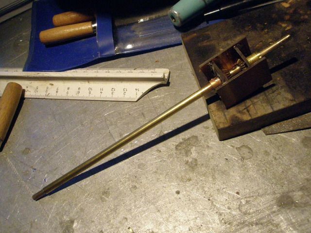
Venom helo , 2 motor counter rotating shaft assembly2.5 inch at the widest point.I can replace the plastic outer shaft with brass tubing and replace the mainshaft with a longer rod, to suit the LOA to the hub carrage bearing at the cone.
While attending Torpedoman A-school I learned that the counter-rotating propellers on the MK-37 family of torpedoes used a motor whose field winding assembly, as well as the armature, was free to rotate within the motor case. The after propeller was coupled to the armature, and the forward propeller was coupled to the field assembly. Not only does this arrangement eliminate the counter-rotation gear-box, but reduces noise, and assures perfect torque balancing so that net torque presented to the vehicle is a big, fat ZERO! Neat.
I'm thinking of taking a motor, put the entire motor case on a bearing so the motor can rotate. Then it's a simple matter to couple the motor to the outer shaft (forward propeller), and drive the after propeller from the normal motor drive shaft. The motor would sit in the wet (good for one season, at least). Slip rings and brushes would get power to the rotating motor assembly.
If I ever work out how to transfer a stock motor armature-commutator assembly onto a hollow shaft, then I would be able to use two motors in tandem -- The forward motor driving the after screw, the after motor driving the forward screw.
OK Manfred, thats impressive. I like the simplicity with the pinion gears of your design. I have been fooling with the motor and mast section of a Venom helo which has counter rotation. Its rarher complex with two motors, but it gave me the idea of a two shaft single motor output, that I already have. only need one gear on each output shaft and a recpricle gear on the inner and outer shaft. Its not that complicated but I like your Idea better. My big question is, what your gear supply source? Also, if water is a problem with the gear tollerance, seal the box and fill with ATF. Small cap, tapped into a fill hole on the top plate. Like a full size transmission, you dont want to overfill. Leave some air space, for relief from expansion of the volume of fluid, due to some small heat that is generated. Viscosity changes but no pressure build up.
I have no plans, no specs, just builded this freehand, used my experience to get this gearbox running, it's a one off, so no documentation either, by the way, i thought you were working on a Bronco Seehund 1:35?
Like you allready know David, i made a "spinning" start.
I'll fill in the story, i was very interested into Gene's magic gearbox, figured out how it worked and made a gearbox of my own, this happened a few days ago, got some very usefull information from David about using it in a wet enviroment.
He explaned about running the gears as sloppy as possible, why?, it's all about fysics, you can't compress water, so a very small tolerance between the gear-teeth will grind you to a halt and mess up your gear.
I decided to use a different approach, and took conical gears, this way you don't need that much parts, there is a catch, when building it up everything has to be in line, if you don't, you're going to loose some teeth.
One of the testruns i made last evening, also did a test flooded with water, no difference, running smooth all the way, it's seems to be sloppy, but that's the intension.
Later on the week i can catch up the enlarged drawings, i ordered two, one to cut in pieces, the other one for measurement and building up the master.


Leave a comment: