Japanese Class A 1/16

Collapse
X
 
  • Time
  • Show
Clear All
new posts

  • He Who Shall Not Be Named
    replied
    Of course, if you are lazy, you can make either of the two propellers free-wheeling and let it pin-wheel in the water.

    M

    Leave a comment:


  • Von Hilde
    replied
    Manfred, I ran them dry first then wet. They were cool wet. I am building another but some internal modifications. No more sloppy gears. I want to try those pinion gears , but use two latteral trunions. Dave talked me into two idlers to bear the torque. I will try that set up in a round container so it will fit aft of where the cone seperates from the hull, With a shorter set of shafts, there wont be as much vibration, and of course a set of semi ballanced props will help. I found some sutable Raboesch 1940 design 4 blade. The nice thing about them, is you can get a large diameter LH for the forward and a smaller diameter RH for the aft. Flat hubs, so you only need to cone the aft with a small model plane spinnerClick image for larger version

Name:	Raboesch type A.jpg
Views:	1
Size:	4.9 KB
ID:	9776820 degree pitch at the hub. Found a nice supply of cone gears, plastic with brass hubs, and in colors. Robotics supplier in England, called Technobots, reasonable as wellClick image for larger version

Name:	cone gear.jpg
Views:	1
Size:	2.6 KB
ID:	97769
    Last edited by Von Hilde; 03-17-2015, 03:27 PM.

    Leave a comment:


  • MFR1964
    replied
    Von,
    Did you run it also underwater?, or did it run hot on dry land?, i've tested mine both ways, no problem at all, you have to keep your gears as sloppy as possible, i run metal gears.


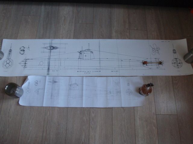
    The second step is made, got me my enlarged drawings, i must say the length is not bad about 137,5 mtr or 4 foot 7", also want to thank both David and Gene to make this possible, next step is making the ribs and getting some RenShape.


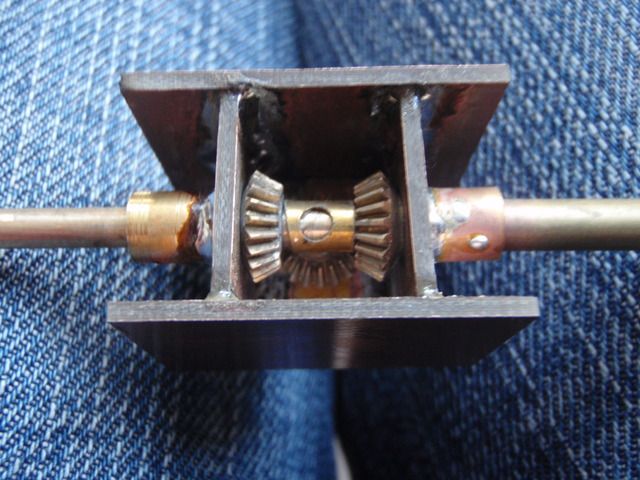
    This one is for you George, as you can see i use three pinion gears, you could go the way like Von, looks to me much easier to make without a lathe, as for the brand of the pinion gears, i suspect they are from Aeronaut, i bought these from the shelf at the local hobbystore, so i really don't now the exact brand.


    Manfred.

    Leave a comment:


  • Von Hilde
    replied
    Originally posted by redboat219
    Any luck so far?

    Was expecting you'll go with building your own contrarotating gearbox.

    BTW, with the tandem motors vs single motor with contrarotating gearbox, which would be more electrical power hungry?
    I think the Doctor M, will be tied up with his and Mike's new toys for a while, but as far as power draw goes, It would depend on the size of the particular motor or motors amperage draw. I would say most models are way overpowered to begin with, so stepping down to two small motors can be better than one big one that has to overcome the friction drag in power, caused by the gear box. The loose tollerance of the gears to allow the compressed water passage is a bigger deal than suspected. My prototype box gets hot after a minuite or so running on the drill power during tests, and thats with the plastic gears. Thats why its a prototype. The next one will have bearings, instead of bushings thruout the drive line. The Idea of two small motors, side by side with the drive line in between might be the most efficent all around.

    Leave a comment:


  • Von Hilde
    replied
    Prototype works fine,just stuck some Revell plastic props to see it work.Click image for larger version

Name:	image.jpg
Views:	1
Size:	61.1 KB
ID:	97734

    Leave a comment:


  • MFR1964
    replied
    Tea and scones guys?

    Leave a comment:


  • He Who Shall Not Be Named
    replied
    Originally posted by Von Hilde
    The Cat fell asleep from boredom, or he would have told me that
    (in the urgent voice of William Shatner) "cat... must.... be.... destroyed!"

    Leave a comment:


  • Von Hilde
    replied
    The Cat fell asleep from boredom, or he would have told me that

    Leave a comment:


  • He Who Shall Not Be Named
    replied
    Originally posted by Von Hilde
    [ATTACH=CONFIG]30431[/ATTACH]After a few hours of consultation, His Royal Higness, Tigger the cat said,"Why stick a square box in a round hull?" Only one trunion, will go on a pin thru the side of the case. Teflon shims will adjust the slop in the play
    ... because you want to ballance the lateral pressure presented by the bevel-gear. Use two, not one.

    M

    Leave a comment:


  • Von Hilde
    replied
    Click image for larger version

Name:	image.jpg
Views:	1
Size:	56.4 KB
ID:	97719After a few hours of consultation, His Royal Higness, Tigger the cat said,"Why stick a square box in a round hull?" Only one trunion, will go on a pin thru the side of the case. Teflon shims will adjust the slop in the playClick image for larger version

Name:	image.jpg
Views:	1
Size:	57.2 KB
ID:	97720Ok, two trunions, and now an end cover to keep the input shaft in line and its on to some propeller issues for a drill motor test, then I can scramble some eggs in a bowl.Click image for larger version

Name:	image.jpg
Views:	1
Size:	47.2 KB
ID:	97721Click image for larger version

Name:	image.jpg
Views:	1
Size:	56.2 KB
ID:	97722Click image for larger version

Name:	image.jpg
Views:	1
Size:	56.6 KB
ID:	97723
    Last edited by Von Hilde; 03-16-2015, 11:37 AM.

    Leave a comment:


  • HardRock
    replied
    Originally posted by He Who Shall Not Be Named
    Good stuff, HardRock. Tell me more about the outrunner. How do you get two counter-rotating outputs from the thing. Most interested in this.

    M
    The central (black) mounting ring has three lugs that carry three spacing rods to mount on the silver bracket at the left of the photograph. Just read this back and even I don't understand it. Here's a photograph.Click image for larger version

Name:	IMG_0807.jpg
Views:	1
Size:	89.9 KB
ID:	97716 or two Click image for larger version

Name:	IMG_0809.jpg
Views:	1
Size:	91.6 KB
ID:	97717 Click image for larger version

Name:	IMG_0812.jpg
Views:	1
Size:	93.2 KB
ID:	97718 The front out runner is directly connected to the large (black) forward spindle and the rear out runner drives the central (silver) spindle. It needs two ESCs to run and provides quite a serious amount of contra-rotating power.

    Leave a comment:


  • HardRock
    replied
    Originally posted by Von Hilde
    There seems to be quite a few solutions to the contra counter egg beater enigma. With this many people workig on a design, it should produce several ideas that work. At this point, it looks lke everyone's rig has to be fine tuned, for various reasons. Sort of like a defense dept contract and all the contractors are scrambling to get a proto up for bidding. One thing I notice, is the metal gears are nice looking, but have such a tighter tollerance, are subject to water compression, and are noisey. The plastic gears, not so much. Price would be another factor. Corrosion, in my case, is a big issue. copper and brass end up looking like the Statue of Liberty in less than a week. That green funk builds up quick. I dont want to have to take the gears out once a week to polish, like I have to do with the cymbals on my drum kit. So I'm taking the day off working on the type IX, and jummping into my old gearbox, and rummage around the junk bin for usable parts.[ATTACH=CONFIG]30427[/ATTACH]Its a start. 4 gears one bicycle spoke, one telescoping portable radio antenna, now a cup of coffee, and find a magic wand.
    I love this McGuiver. A used thum tac, a small bottle of nitro glycerine, a copy of the girl guides field manual, one used condom and a hamster. Yep, we're ready!

    Leave a comment:


  • He Who Shall Not Be Named
    replied
    Originally posted by HardRock
    I also tried this [ATTACH=CONFIG]30426[/ATTACH] as a refinement of the crown and pinion wheels and again, it worked but it was no where near as smooth as the final gearbox that used old nylon servo gears.
    Good stuff, HardRock. Tell me more about the outrunner. How do you get two counter-rotating outputs from the thing. Most interested in this.

    M

    Leave a comment:


  • redboat219
    replied
    Originally posted by He Who Shall Not Be Named
    Good catch, Romel. I'll see if I can punch out a 555's motor-shaft. Film at eleven!

    M
    Any luck so far?

    Was expecting you'll go with building your own contrarotating gearbox.

    BTW, with the tandem motors vs single motor with contrarotating gearbox, which would be more electrical power hungry?

    Leave a comment:


  • Von Hilde
    replied
    There seems to be quite a few solutions to the contra counter egg beater enigma. With this many people workig on a design, it should produce several ideas that work. At this point, it looks lke everyone's rig has to be fine tuned, for various reasons. Sort of like a defense dept contract and all the contractors are scrambling to get a proto up for bidding. One thing I notice, is the metal gears are nice looking, but have such a tighter tollerance, are subject to water compression, and are noisey. The plastic gears, not so much. Price would be another factor. Corrosion, in my case, is a big issue. copper and brass end up looking like the Statue of Liberty in less than a week. That green funk builds up quick. I dont want to have to take the gears out once a week to polish, like I have to do with the cymbals on my drum kit. So I'm taking the day off working on the type IX, and jummping into my old gearbox, and rummage around the junk bin for usable parts.Click image for larger version

Name:	image.jpg
Views:	1
Size:	64.5 KB
ID:	97715Its a start. 4 gears one bicycle spoke, one telescoping portable radio antenna, now a cup of coffee, and find a magic wand.
    Last edited by Von Hilde; 03-16-2015, 06:05 AM.

    Leave a comment:

Working...