CSS Manassas -aka- Steam Atragon

Collapse
X
 
  • Time
  • Show
Clear All
new posts
  • Steampunk
    Lieutenant
    • Feb 2010
    • 62

    #16
    Okay. Things are starting to move right along, now. There's still oodles we'll need to adjust ... but we're getting a 3D shape roughed out. I had begun at the midsection, and moved backwards ... partly because the rear of the craft was probably easier to "see" than that strange bow! I had "saved that for later," on purpose ... figuring that making the stern "look like something" would give me confidence to deal with the bow.

    Sometimes, inertia is your biggest enemy. A good friend of mine has a saying I like, a lot: "Do something, even if it's wrong". I wouldn't advise such a course of action, if dealing with toxic chemicals or lethal voltage levels, etc. ... but when dealing with paper "slices": hey, why not?


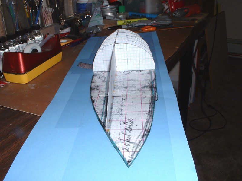
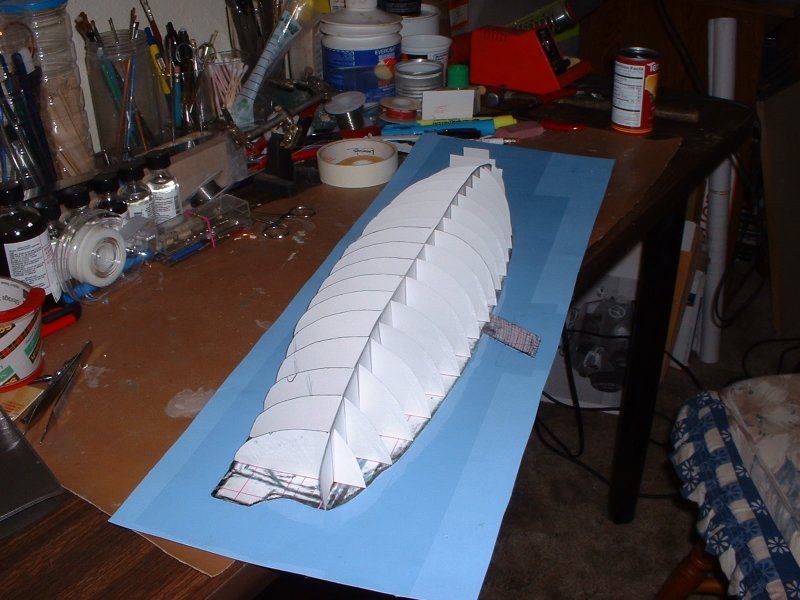
    Most of the info above, as you can easily see, can't possibly be ready for prime time! But it's a starting point. And perhaps more importantly: it's a starting point that's based, not on a "wing it, by eye" sort of "seat of the pants" vague feeling of what the original thing might have been shaped like. It's a good starting point, which sorta-kinda makes sense in some areas of the craft ... that began with a historical "blueprint"!

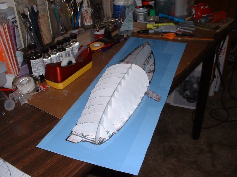
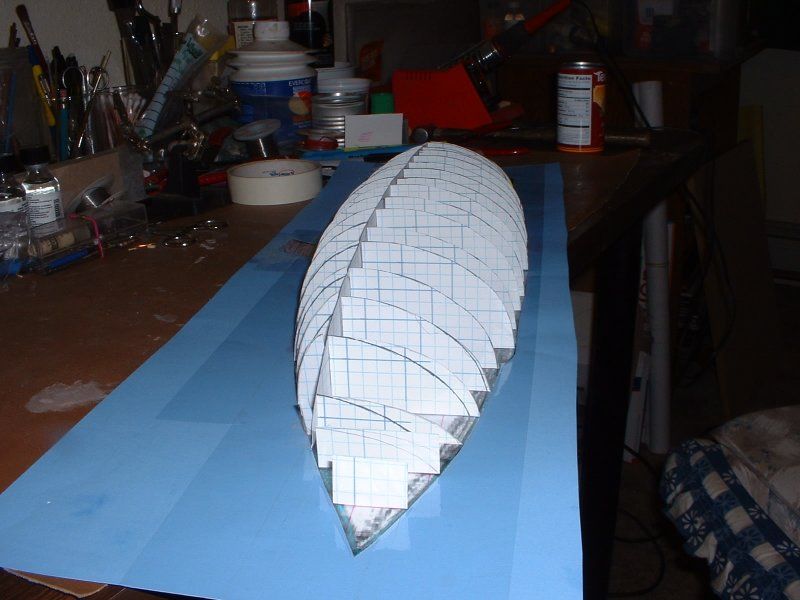
    Had that blueprint included a plan view drawing (top or bottom) ... or even some nice, orthographic "end views" we could avoid a lot of what we're having to deal with, in these steps. But with this methodology, you can still get there. It takes serious thought, and some "bravery" (to not want to look foolish, or crazy; especially in these very early "baby steps" phases of "figuring out the shape") ... but the sytem works well enough to get you to the point where you can, without much fear of loss or embarrassment or whatever, start shaping "solid parts".

    We're clearly not to that point, yet ... but compared to only having a side view drawing, and one cross section, we're light years ahead now!

    Comment

    • Steampunk
      Lieutenant
      • Feb 2010
      • 62

      #17
      What's needed, at a point like this, is some "resting your eyeballs" time.

      Which is exactly what I did, once I had that initial work in a form where I could look at the overall rises and falls and curves, from multiple angles. I literally stuck the whole thing up on a wall, for multiple days ... and just left it there, without making any changes to it.

      Over time, certain areas will "jump out at you". When they did, what I did to deal with it was to simply write myself a Post-It Note, describing that one problem. And not worrying too much, yet, about a solution. That will come later! For now, you just have to let your head wrap itself around the overall proportions, outlines, and contours you have created. Get used to seeing what you've done. Good areas will be there. And some that just flat look wrong. And many that you can't decide if they're right, wrong, or just plain confusing. Just let it all sit, untouched.


      Comment

      • Steampunk
        Lieutenant
        • Feb 2010
        • 62

        #18
        At some point, a little bit down the road, I convinced myself that it didn't make sense to totally ignore one major task that, thus far, I hadn't dealt with. The props! I knew I'd need some sort of a "cut out" for them to be in. Some "negative" area where they could safely spin.

        So, while I still hadn't gone through my stack of Post-It Notes, and treated them like a "punch list" of items that needed fixing, I felt it was best to tackle that one major remaining problem, whilst things were still in the "cheap and easy" paper stages of things. I could do any fixes, elsewhere, later; but it seemed to make sense to deal, at least in an initial way, with that one major area of interest that I hadn't really done anything with, yet. So, the plan was for me to mostly just leave the whole thing on the wall, for a while ... but, I did a bunch of searching around, in various books and on the internet, to study "real boat hulls" from this same time period. When I felt I had enough info, I did this:


        After this, my collection of photos tells me I switched over to some MDF "wood" scraps, to continue the initial "seeing it in 3D" steps ... but I'm sure that if I went through the paperwork that's associated with this project, I'd likely find that I had "documented" each cross section's full shape, first. That is, pulled each section in turn off of the "spine" or side view drawing or whatever you want to call it ... and traced what I'd come up with, so far. Then, for purposes of continued study of the paper model, I re-assembled that "skeleton" and stared at it for a while.

        It'll probably take me a few days, maybe longer, to get my photo collection into some sort of reasonable order ... then, we'll resume this story. I'm anxious to show the steps I took, and the photos which resulted, when I arrived at the bow shape that I ended up with. It's based, more than one might think, on that 1861 dockside, eye-witness drawing by J. A. Chalaron ... but I'll take a break, and then we'll deal with the bow.

        Comment

        • He Who Shall Not Be Named
          Moderator

          • Aug 2008
          • 13393

          #19
          Very good stuff, Ward. You're taking us all back to school.

          M
          Who is John Galt?

          Comment

          • greenman407
            Admiral
            • Feb 2009
            • 7530

            #20
            Great! I certainly would not call that a messy workbench at all. Its , by my standards, quite pristine. Usually dictated by how much room you have and your cumpunction.
            IT TAKES GREAT INTELLIGENCE TO FAKE SUCH STUPIDITY!

            Comment

            • Steampunk
              Lieutenant
              • Feb 2010
              • 62

              #21
              And now for something completely different ...!

              I'm making pretty good, behind-the-scenes progress: regarding going through the "reconstruction" of the info I had once collected on this crazily fascinating, 1860s attempt at stealth technology. One unexpected bonus of going through all of the photos (which were stored, "all over" prior to recently) was remembering that I didn't write one article about the CSS Manassas. I had actually written two! And bits and pieces of the first one, although I had never got overly serious about submitting it for publication, look like they're worth posting here.

              The truth as far as how I could forget I wrote an entire article, once meant for publication ... and then forgot I'd done so ... is probably more along the lines of, "Geez, do I ever have to get organized!" ... but for humor's sake, I'll blame my publishers over at "Sci-Fi & Fantasy Modeller". I'll claim they have writers like me pretty well trained: as far as having a mindset I might describe as, "Submit it; forget it; do another".

              Anyway, what I unearthed was the text for an article I had started, two years or so before the model seen above was actually finished. Some of which isn't actually bad: as I re-read through it now. So, when I run into one of these periods where I can't upload much, here -- (trying to get More Organizee (tm) on figuring out which old-to-me photos to upload, where; and what to say about what's pictured in them) -- what I may do is to take a chunk of the first, never-published article that I wrote back around 2008 / 2009 ... and post bits and pieces of that, here.

              I'll post the first big chunk, after this posting ... but since I don't want to have to re-invent the wheel, later, TOO many times, I may also try to summarize my previous efforts with this project. Partly just so that I won't have to "reconstruct" what I did, when, and why; at some later time!) I may just leave that stuff as "note to self" sorta things, on a hard drive somewhere. We'll see. But the article fragments from the first time I sat down and tried to write something up, about this crazy attempt at 1860s naval combat stealth, should interest some folks here; so, that will be what I'll post, next.

              I probably won't post all of that article, however. Too long! And some bits were made obsolete, as research had continued. In some places, I like the sections I later wrote (from scratch) for my current publishers, from England -- so, later on, as I try to describe the processes I used to best visualize the "real thing," (as best I could given limited research data, etc.) I may re-use some of the published article's text. Which would make this I'net forum posting sort of a "best of" collection, as it were: of research work and analytical work done, over the last half-a-dozen years or so. I'll try to keep things Halfway Organizee (tm), though. Which may not be easy, given how much ground there is to cover!

              The plan at this point is to attempt to group things, organizationally speaking, by what part of the boat I'm trying to discuss or focus on, at any given time in this message thread. The bow's analytical work will be one of the first things I work on, once I have the photos all sifted, etc. and am ready to do another semi-lengthy, "only focused on one area or task" mini-discussion. Reasons why I stuck a turret in back, and how I actually did it, are also planned for mini-discussions, later on. Et Cetera. In other words, I'm planning this write-up in "subassemblies".

              Since I just wrapped up a "subassembly" discussion, on the "Paper Skeletal Half-Model" portions of the analytical work, this seems as good of a time as any, for a bit of a break. I'll show two sort of "introductory" and "get excited about the real thing" sub-sections, from the unpublished article I wrote around 2008 or 2009. (For what it's worth, before I wrote regularly for "Sci-Fi & Fantasy Modeller," my plan for the stuff I'm about to upload and "quote myself on," was intended as the first half of a two-part article I once wanted to see in the SubCommittee Report. For various reasons, that plan had fallen through, at that time ... but it seems like a shame not to publish it here, since space so permits, etc.)

              If nothing else, the following write-ups should show how excited I once was, about the CSS Manassas ... and why I thought it was so cool!!

              Comment

              • Steampunk
                Lieutenant
                • Feb 2010
                • 62

                #22
                Here's the first section of my unpublished (2009-ish) article about the CSS Manassas

                Sometimes, truth is stranger than fiction. The boat I’m about to discuss really existed – in one form or another. However, research into this boat’s abilities is no easy task! There’s so much chaff and so little wheat that separating the two is like trying to confirm or deny grains of truth within ancient myths.

                No photos of the boat are known to exist. Drawings are relatively plentiful … but some folks might say they were akin to research into extraterrestrial life forms: you either believe in that sort of thing, or you don’t. Drawings “prove” very little. (But they can be interesting! I plan to include working drawings of the shape I came up with, in the next installment of this two-part article, so others can build a scale model.)

                Personal beliefs about what was possible and likely, given the time period and circumstances, must weigh heavily in any discussion of this historical boat. As far as any serious attempt at historical analysis goes, I expect that some folks will side with vertical thinking: that is, trying to strictly categorize the boat with what came before it, invention-wise. Such folks may think I went too far – and may point to a lack of others saying what I’ll say, as their proof. Others may side with lateral or “outside the box” thinking. Those folks may believe I didn’t go nearly far enough. The truth, I expect, is some mix of the two thinking styles.

                Ultimately, the only way to prove or disprove the accuracy of anything said about this boat would be for someone to take Clive Cussler's advice, and dig up the real thing. He claims it's under mud, on a US riverbank: he even shows where, on a map. It's an important part of naval history, so I hope the CSS Manassas gets the same professional study and attention as the CSS Hunley.

                http://www.numa.net/expeditions/manassas_louisiana_arkansas.html


                WOODEN SHIPS

                Imagine living in America during the mid-1800s. Wooden sailing vessels have been around for thousands of years. Cannons on ships have been around since the 1350s. Steam power has been around for a hundred years or more – but only in experimental form. It has slowly gone from being dangerous and inefficient, to managing to catch up to what ships and boats powered by nature have done “forever”. It still isn’t practical as a form of long-distance power, so the dominant way to travel across water is by sailing.


                RUDE AWAKENING

                Now try to imagine being stationed on one of those cannon-equipped wooden ships, during the early part of the American Civil War. You're on one of four Federal warships assigned to blockade the Rebels on the Mississippi River.

                For the most part, you and your shipmates find blockade duty to be rather tedious and routine. That's because the North presently has many war ships, with a large capacity for building more; while the South has virtually no warships, and little capacity to build others. The war on land may be another story, but some folks feel that adds up to a very one-sided conflict on water; with the outcome virtually certain.

                It's a particularly dark night. All's quiet. Routine.

                Suddenly, an alarm goes up. A lookout yells that he thinks he’s seen something in the water, thirty or forty feet from the ship. Other crewmembers look for it, and yes, something’s moving in the dark waters. It’s nothing natural, however: whatever’s moving out there is too low, too dark, and wreathed in too much black smoke to be presumed friendly.

                The small machine arrives – with a deafeningly sharp, lingering crashing-booming noise. Something huge has struck the ship, with great wrath: something way out of proportion to what was seen on the surface. As crewmembers struggle to regain their footing, the sound changes: it almost sounds like something’s trying to eat the ship! Horrific squealing, tearing, wet cracking noises disorient and terrorize those on board.

                Enough military discipline remains, however, that the crew sends up signals to warn the rest of the fleet of the attack. And then nothing – that is, no loud noises except small arms fire and shouted commands trying to train ship’s cannons on the attacker … which moved off, and is steaming towards other Federal prey.

                The fleet's crews are demoralized to their core, when they fire at it. Cannon balls, aimed at the presumed deck, simply pass through the smoke that surrounds the craft – hitting nothing. Cannons aimed at the machine’s presumed waterline, simply disappear into the smoke and then loudly, freakishly ricochet off – also doing no damage. The river monster keeps attacking – and there’s nothing anyone can do to stop it!

                The “Infernal Machine” sends up a signal rocket. Other Rebel vessels, including chained-together rafts full of flammable materials, join the fray against the four wooden warships. The Federals feel they have but one choice left. By daybreak, they’re as far away from their nightmare as conditions allow them to run.


                AFTERMATH

                I’m not making that story up, believe it or not. It’s my reconstruction of the naval battle at the Head of the Passes, at the mouth of the Mississippi River on October 12, 1861. The attacker was the CSS Manassas.

                I believe the boat’s designer, one J.J. Peetz, used much lateral thinking – including psychological terror and “this isn’t possible” disorientation – as part of his design’s weaponry. I believe he thought hard and long about how to make his infernal machine just that: a war machine that those being attacked would feel was designed and built by hell itself. But we’ll get to that, when we talk about design features for scale models.

                Things went so badly for the Federal fleet, that night, that Captain Handy of the USS Vincennes ordered his grounded-but-intact warship to be abandoned during the fight. (He later claimed to have misunderstood a signal from the flagship.) Two weeks later he lost his command. He was not alone: Captain Pope, of the flagship USS Richmond – the ship that was rammed, above suffered the same fate.

                Two examples of the deep psychological terror inflicted by the CSS Manassas are just now coming to light, thanks to the Internet publication of a private journal of a US Navy Warrant Officer aboard the USS Vincennes. Nicholas Lynch wrote, in an almost off-hand way, that the crew of the USS Richmond so greatly feared another attack by the Manassas that all it took to put the crew into a panic was seeing the planet Venus rising. (Someone somehow mistook Venus for a signal rocket from the Manassas, and the whole ship went to general quarters.) There’s also talk in Lynch’s journal – and nowhere else in admitted, official history – of the Vincennes’ crew having broken into the Officer’s Mess after the first attack, and having a “glorious blowout” on the forbidden meats, sweets, and whiskey they stole.

                http://www.ijnhonline.org/volume1_number1_Apr02/article_oxley_journal_blockade.doc.htm

                Meanwhile, Southern newspapers laughed for weeks at how badly the Manassas had kicked the Federal’s butts. The machine gave hope to Southerners – what unstoppable machine wouldn’t? – which of course meant that Peetz’s and other’s lateral-thinking efforts would be taken much more seriously by builders. The situation that arose was the South suddenly emboldened to create other wild monstrosities, and the North greatly fearing the loss of their present advantage on water. The North did all they could to pretend the Southern success wasn’t repeatable: just the fault of a few cowardly Captains.


                HISTORY LITE

                You may be wondering why the CSS Manassas isn’t better known? I certainly did. I think the answer is brutally simple: the North eventually won the war, and the North went on to write the history books.

                Northern newspapers like Harper’s Weekly make it clear that the Union pretended that Southerners had not broken military and public morale, or been able to easily toss military discipline into a rubbish heap with a single vessel. Why change that story, after the war had been won? The South knew different, of course, but were not in any position to correct the record: designs for war machines that broke long-established rules of combat were considered to be unchivalrous at best, and hang-able war crimes at worst. Hence the burning of much Southern technical information, by Confederates forces, at the end of the war.

                Southern secrecy and Northern propaganda clouds and distorts most research into “infernal machines”: hence my comments in the introduction about there being very little wheat, and quite a bit of chaff.

                Still, some causes and effects can be reverse-engineered. For instance, it made no sense to me, even as a school child, that the CSS Virginia and the USS Monitor suddenly appeared on the world’s stage at almost exactly the same time; and made centuries of wooden warships obsolete overnight. As a school child, I asked how that could have happened. I was told that it was just time for such thinking to have happened; and that it just happened simultaneously, on both sides of the Civil War. Even as a lad, I found that explanation lacking. (And I don’t blame my teachers: rather, I blame their teacher’s teachers, etc.)

                Now I know more of the truth: there was one “infernal” machine that was fighting before either of those much-better-known ironclad war machines had first gotten wet. The war’s first ironclad proved certain concepts so well that both sides rushed to include them in the next generation of ironclads. Those features being: not much visible above the waterline to shoot at; a rounded or slanting shape, so cannon balls could not penetrate; and a heavy wooden under-structure covered with iron armor.


                PRIMARY SOURCES

                If you want to find out more about the history of the CSS Manassas, here’s a great (but slow!) research site:

                http://www.history.navy.mil/photos/sh-us-cs/csa-sh/csash-mr/manassas.htm

                I found two things there that I really like, and believe are great resources. One is a 1903 New Orleans Picayune newspaper interview of Captain J.J. Peetz. He claims to have designed the Manassas. The other is an 1861 drawing by J.A. Chalaron. The former told me a fair amount about some of the operational features. The latter was a great starting point on figuring out the shape of the boat.

                Other resources included scanned-in back issues of Harper’s Weekly. I often filed their engravings under “interesting but not overly trustworthy” since Northerners tended to see the Manassas only at night, while they were being attacked by it.

                http://www.sonofthesouth.net/

                Newspapers of the time often seem to have habitually played fast and loose with the truth: excitement and entertainment apparently sold more papers. Mark Twain’s short story “Journalism in Tennessee” (1871) is one of my favorite pieces dealing with writing for emotional effect, and its unintended consequences.

                http://www.gutenberg.org/files/3189/3189.txt
                Last edited by Steampunk; 08-02-2014, 04:16 PM.

                Comment

                • Steampunk
                  Lieutenant
                  • Feb 2010
                  • 62

                  #23
                  Here's the second section of my unpublished (2009-ish) article about the CSS Manassas

                  TAKING ON WATER

                  Let’s talk about some features of the historical boat. Earlier, I called this boat a semi-submersible. What I mean is: the historical boat was not a true submarine. This was partially because it operated in shallow inland rivers. Just looking at the shape of the thing, as I’ve developed it so far: all it would take (externally) to make a cool sci-fi’ized version of the thing as an R/C submarine, would be a set of “fins”. (Dive planes.) I plan to make fins optional, on my upcoming scale working drawings.

                  References vary, but all I’ve seen agree that it sat very low in the water – with only two to six feet visible while operational. My feeling is that the real thing very likely had a sub-like ballast system to adjust its freeboard, or height out of the water. Two or three feet were visible for combat or pre-combat “stealth” purposes, with more seen if needed – for instance, to be able to travel over a shallow river’s sandbars.

                  I also imagine that the boat raising up or lowering for an attack run would have had a chilling effect – all the more so after I worked out the 3D shape of the nose, which resembles some prehistoric sea monster.

                  I realize that some readers may feel cheated with a “non-sub” being discussed. (Sorry!) Keep in mind that even as late as World War II, diesel / electric submarines had to be operated on the surface most of the time. Until nuclear power became practical, virtually no submarines operated underwater the majority of the time – so I’m cutting this boat’s designers a certain amount of slack, for being born a century too early.

                  Why do I think the real thing may have had a sub-like ballast system? A combination of several factors. References vary widely for many of the Manassas’ specs – so that discrepancy alone is weak proof. It shouldn’t be discounted, however. One way to explain the disagreement would be to assume they had a way to take on water and to pump it back out, as needed. The principle was well understood at the time.

                  Peetz’s newspaper account may hint at a ballast system. First clue: “We left the city for Fort Jackson and remained there eight days, and then went down the river to within a few miles of the enemy's fleet, then laying in Southwest Pass. Being very low in the water, with a short smokestack, we were hidden from their view by the high marsh grass, but by raising our Jacob's ladder we could plainly observe their movements. We laid there several days, waiting for a dark night so as to take them by surprise.”

                  Second clue: “I was not on the Manassas on her succeeding trips, but would like to say a word as to what became of her. During the Spanish-American war a Northern paper stated that Admiral Dewey, then a Captain, had sunk her during the fight at the forts, but this was an error.” He later says: “Orders were given to abandon and blow up our vessel, the Louisiana, which we did, and along with the officers and crews of the other vessels we started on a long march of eighty-five miles to the city, on the right bank of the river. I met Capt. Warley of the Manassas on the way, and marching together, I asked him what execution he had done during the fight. He replied that he had done nothing, but had the water supply pipe cut and let her sink at her mooring. Thus ingloriously ended the famous ram Manassas.”

                  My conclusion: the ability to hide a relatively large Infernal Machine for days, behind “high marsh grass” hints at a craft that could sit on the bottom of a shallow river, if need be. I have to also seriously question why a “water supply pipe” would have been designed in such a way as to allow the boat to sink, if those pipes were cut? That only made good sense to me, if those pipes fed external water into ballast tanks.

                  But Peetz hints at a ballast system, even more strongly: “…having had experience in seafaring and the construction of vessels in the Crimean war, on board the English line of battleship Orion, of ninety-nine guns, I began the study of a vessel that would be effective and dangerous to an enemy. While stationed on this English battleship, blockading Cronstadt on the Baltic, the small Russian gunboats frequently sallied out, and, having guns of longer range, could lay where our guns could not reach them, and place shots clear through our wooden vessels. I often wondered if this could not be prevented, if something was there to make the balls glance off, or if our vessel set lower in the water with a covered, inclined top, instead of having a high freeboard or height out of the water.”


                  BLOWING SMOKE

                  I won’t totally discount what Harper’s Weekly had to say. I love having access to as many forms of first-hand information as I can get, when I’m doing research. I know that sometimes a minor, off-hand comment may be the last puzzle-piece a lateral thinker may need to complete a picture others can’t assemble well.

                  In the Dec 7, 1861 edition of Harper’s Weekly, an officer from the Richmond was quoted as saying, “At 3:45 on the morning of the 12th the look-out discovered a small, low, dark object stealthily approaching our vessel, emitting a volume of black smoke, totally hiding from our vision her form.” (“The Fight at the Southwest Pass,” page 779.) Several things interest me about that quote. I feel they add up to an 1860’s attempt at stealth technology – and that in combination with the drawing by Chalaron, it tells us a great deal about the smokestacks the Manassas may have used.

                  I realize that most other researchers have envisioned the Manassas with either one smokestack or two; and that their stacks were usually mounted along the upper hull. (One contemporary drawing may show four.) I believe we’re seeing a combination of “before” and “after” in Chalaron’s drawing. I believe one or two stacks was correct – when the boat was a civilian icebreaker or a tug. However, I think after all dry dock work was completed, the revised boat had four low, short stacks; mounted in pairs along the hull’s sides.

                  My theory is that the original smokestack is shown in Chalaron’s drawing, but it was going to be removed. The same profile view shows two semi-rectangular objects, located along the sides of the boat. (Note that the hull’s shape would camouflage them from view, from nearly any but a fatal viewing angle.) The angle of their backwards tilt, if you notice, exactly matches the angle of the tall stack. Further, those semi-rectangular forms are completely the wrong shape to imply openings in the curving sides.

                  And why would there be openings that large, that close to the waterline, on a boat that had no cannons other than “… two sixty-eight pounders, one over the stem and the other over the sternpost”?

                  All in all, I believe Peetz consciously did what the Richmond’s officer claimed: he made it so that the boat would be hard to see – because it sat low in the water, and because it was painted a dark color – but also because the craft shrouded itself in smoke, as an additional form of visual stealth.

                  That’s all we have time for, at present. Next time we’ll finish discussing the known features of the real thing. I plan to show you my finished (probably static) scale model of the Manassas. So far, I’m still working on “half-models” – which I use to refine and test the best 3D interpretation of all available data. If space permits, there may be a few “teaser” pictures of those half-models, with this article. If not: next time!

                  Comment

                  • Steampunk
                    Lieutenant
                    • Feb 2010
                    • 62

                    #24
                    (Interrupting myself, to add some comments -- before I resume uploading old text)

                    I'm looking over that old article of mine, and thinking that maybe I should upload another portion of it ... but, before I do, this seems like a good place for me to point out that some of the stuff I said, above -- (such as the possibility of a water ballast system being used to adjust freeboard or height out of the water) -- now seems to be "proven". What I mean is: on another web site's collection of on-going message threads (over on a set of forums related to discussions of the American Civil War: I'll find that portion, again, later; and post a direct link to it) there's a long quoted section from a seemingly very trustworthy source. When the Enoch Train had been used, before the war, with one particular set of owners, it was used in a very specific way that is described in post-war documents. In discussing how the Enoch Train was used to get mud up off the bottom of certain shallow rivers, just such a ballast system was described. The original boat, in its pre-Manassas form, already had huge water ballast tanks installed. These tanks were there to allow the operators to sort of "sink the back end" as it were; enough to have the propellers, believe it or not, used more or less like the "mole" seen in various episodes of Gerry Anderson's Thunderbirds TV show from the 1960s! Fans of lateral thinking, and of technology from the era of steam, should find that discussion in those post-war documents fascinating!

                    One other note on the stuff I said in part two of that old (to me, anyway), unpublished article I was once thinking of submitting for publication in the printed R/C sub enthusiast's "SubCommittee Report" -- and then, I may post another section of that old article. The note on the stuff said, above, being this: I still am under the impression, from studying J. A. Chalaron's 1861 pencil sketch, that the "real thing" may (key word!) have had FOUR short smokestacks, instead of the two I am showing on my "finished" model. Keep in mind that when I resurrected the then-two-years-old work I had previously done, on that "set aside for a while, as I work on other projects" model I had previously begun, of my interpretation of the CSS Manassas, that it wasn't a model I was going to submit for publication in the SCR, any more. Suddenly, my editor for the scale modelling work I was then doing for SF&FM had told me, in e-mail, that discussions were going on, behind the scenes, between himself and the two co-publishers, at that point. The thrust of those talks being that there was a possibility that they'd do a "Steampunk Modeller" special issue. (Which they did, once they'd seen the positive response from several of their "regular" writers; including myself.) So, I was suddenly faced with a chance to get that "unfinished, and gathering dust" model of the historical version of the CSS Manassas, as a "fictional" model. And to make my "serious" model be a good fit for that upcoming / possible special issue, I had to sort of "slant" things a bit, into the world of science fiction. As I told Andy Pearson, my editor: the real thing is so crazy looking, and has so many wild features, that I really wanted to leave most of it as-is and "serious". So, we agreed that it should be enough for that audience, if I painted some eyes and teeth on the model. (Once it was finished, which it still wasn't, at that time.)

                    Since the model itself had suddenly become a "deadline" model, and it wasn't even fully built, and I had a LOT of scratch-building work to do, to get it in on time -AND- since I had to sort of (gently!) spice things up, a bit, for inclusion in that "Now a GO!!" special issue, the decision was made to only build TWO of the short smokestacks ... instead of the four that I believed, then and now, that J. A. Chalaron's 1861 dry dock drawings might be indicating was the case.

                    The long-term solution, down the road, would be for me to "revamp" my existing model: and to add the two forward smokestacks; to go with the ones in back.

                    (And to get rid of that "eyes and teeth" paint job, up front, while I was at it!)

                    With that all said, I think I'm gonna upload the third portion of that earlier, aborted article's text, in its entirety. Most of it still seems mostly-relevant, so why not upload it? (Even if, throughout the whole of the article, maybe I'd have re-written some conclusions or otherwise made updates to that older article.)

                    The fourth section, I may have to alter a bit, before I post that stuff. Or maybe just delete a few paragraphs, or whatever. That portion, as I re-read it now, looks a lot like it was "forward-looking" stuff. Stuff I was writing about, in rough draft form; but that would probably change, once the model itself was done. It looks like, in re-reading this nearly-forgotten, aborted article, that I was focusing more on the tightening up the bits in "part one" (the stuff I've already uploaded, above) ... figuring that since I had this pictured in my mind as "part one" of a two-parter, that I still had time to finish the model; and do any needed re-writes on "part two" of that article. But, instead, other projects pushed the Manassas off of my bench, in the short-term, back then ... leaving the fourth section pretty "sloppy" and "iffy," in comparison to the tighter, more detailed stuff I'd written above; and to an extent, in the section I'll upload, momentarily.

                    With that said, the next upload will be the as-originally-written first half of the second half of that once-planned article. (If saying it that way makes sense?)

                    Comment

                    • greenman407
                      Admiral
                      • Feb 2009
                      • 7530

                      #25
                      Just thought I would paste this link for others:http://www.history.navy.mil/photos/s...r/manassas.htm
                      IT TAKES GREAT INTELLIGENCE TO FAKE SUCH STUPIDITY!

                      Comment

                      • Steampunk
                        Lieutenant
                        • Feb 2010
                        • 62

                        #26
                        Here's the third section of my unpublished (2009-ish) article about the CSS Manassas

                        ICEBREAKERS

                        The privateer CSS Manassas began its life – depending on which historical accounts you trust the most – as either a civilian tug boat; a towboat; or an icebreaker. I’m open to input, but at this point I believe the icebreaker story makes the most sense. In part, this is because my research into icebreakers led me to the fairly modern, steam-powered icebreaker Stettin:

                        http://www.dampf-eisbrecher-stettin.de/

                        I don’t want to give the impression I had an instant and overwhelming trust in every aspect of Chalaron’s drawing. (Or anyone’s drawings: not excluding my own!) While the drawing looked cool in some ways, my first impression of the hull’s cross section was a “Yeah, right” dismissal.

                        I initially thought it was an odd shape for a vessel that started as a wooden tug or tow boat. I thought the bow area should be more like an axe’s blade. (Because I didn’t then understand how icebreakers actually break ice: they push themselves on top of it, and wait – not smash into it.)

                        Research showed me that hulls on purpose-built icebreakers (from any era) have to be both very strong, and smooth. That’s because ice all around the hull tends to “pinch” the vessel: that is, try to crush the hull, as if it were in a giant vise. The clever solution in use in any purpose-built icebreaker is that the hull shape translates the horizontal force of the surrounding ice, into a vertical motion. That is, as the vessel gets squeezed, it moves upwards instead of being crushed. This upwards motion puts more of the vessel’s mass directly over the ice. So, any ice that tries to hurt the boat, ends up hurting itself. Time and gravity break the surrounding ice, and the vessel moves forward.

                        I also asked myself, “Wouldn’t the boat tend to roll excessively, from side to side, due to its rounded, acorn shape?” The rolling tendency that the hull’s shape might contribute to, could easily be rectified by the addition of some sort of stabilizing outriggers. Peetz’s newspaper interview mentions just that: “On the water line all around she had a solid sponson four feet thick to protect her from being rammed.” (Note, however, that I left that feature off of my working drawings. Research-wise, I had no idea what that sponson’s true shape was; and visually, I felt it would have “spoiled the lines”.)


                        RAMMING SPEED

                        One of the wildest things about the historical CSS Manassas is that while the designers and builders put two cannons on the boat, they weren’t intended as the primary destructive force on this war machine. These days, what we call a torpedo is basically a horizontally-fired missile. (In the 1860s a “torpedo” was the name for what we call a mine.) They couldn’t get their steam-powered boat to submerge, fully; and had no way to shoot missiles out of it, horizontally … so they made the boat itself into a ship-destroying missile.

                        Every text account I’m aware of, agrees there was a ramming device of some kind, added to the bow. Designer Peetz said two things about that feature: “She had a projecting stem below the water line, extending out two feet, for the purpose of ramming.” And: “The boat turned into the ram was reconstructed by putting on an extra bow, made solid and extending out a few feet, with an iron prow for ramming purposes.” Chalaron’s diagram has a notation showing that twenty feet of the bow was made “solid”.

                        I’m interpreting those items to mean that the forward portion of the original boat was made solid (with wood); and that a portion of that new, solid area stuck out, beyond the old boat’s bow area. I’m assuming Peetz meant that the piercing tip of the new wooden addition was a two-foot long, solid iron casting.

                        My interpretation of these historical statements took a while, and went through some changes. The more I studied things, the better I thought I understood what it all meant. Part of that discovery process was to do what I could to “see” Chalaron’s drawing, in three dimensions: so, I built several “study models”.

                        I had an intuitive hunch that one wavy line in particular, near the lower bow, was a careful but abstracted attempt to represent the “top of a hill,” where several complex contours interfaced or met. A way to show the widest points, along the sides of the bow – without showing individual cross section drawings.

                        What I found out is that if I drilled a series of small holes, to mark off that exact wavy bow line, on a solid MDF study model I had built to work out the cross sectional bow shapes, and then “connected the dots” when I shaped the areas above and below that line: several complex areas all made perfect sense.

                        From the bow’s ramming tip, going backwards: Chalaron’s wavy line gently dipped downwards; then gently rose back up; then did an even slower, more gentle, downwards dip. Sort of a shallow “W”. I made my study model’s lower bow convex, below Chalaron’s line. That just seemed sensible; and was a good starting point. The dipping line at the bow implied a concave shape was above that line. The dipping line behind that one was also concave above the line. Between those two, but not visible on the (modern, computerized) copy of Chalaron’s drawing, was another implied raised “interface area” or “top of a hill”.

                        I further presumed that the main hull’s shape was convex. I then had to figure out how to get that aft-most dip or shallow concave area to blend into the main hull, behind it. What resulted, when I came out of “right brain mode” (artistic, shape-oriented) and looked at what I’d done, resembled a sea monster’s skull. The area where the upper part of the ram blended into the main hull, almost looked like an eye socket. The bow looked “nose-like”. The wavy line almost resembled a jaw line, or row of teeth. But this wasn’t what I had in mind, when I was doing the shaping work. I was just trying to follow the “rules” Chalaron had set down on paper; and that’s what resulted.

                        A very complex form! And an interesting one, visually: if only as a bonus. I was mostly concerned that the form matched Chalaron’s sketch well, and looked like something that could be built in the time period. To me, it looks like something smart folks might have come up with then, to expand on what others had done in their past: the ancient Phoenician’s or early Romans, for instance, with their oar-powered warships. (I have the impression that Peetz read up on history, well; and would have been an SCR contributor?!)

                        As with anything in this multi-part article, I’m open to other’s ideas and input … but I think the bow shape I’ve developed ought to be seriously considered by others, as one methodically-deduced possibility.


                        BARBETTES

                        Although some historical accounts claim only one cannon was on board, Peetz’s newspaper interview talked about “... two sixty-eight pounders, one over the stem and the other over the sternpost.” My questions in regard to the guns aren’t how many there were. It’s more along the lines of how they were mounted and used – and there’s really no way to say, for sure, without digging up the real thing.

                        Chalaron’s drawing of the upper stern shows a complex combination of lines that can be interpreted many ways. Above the waterline, the hull’s profile bends in a certain curvature. Then there’s a line parallel to the waterline, which sort of branches off or cuts inward; across the stern. About halfway across that new line, the hull’s outline, changes into an upward-slanting straight line. Above that, the original bend continues.

                        One possible interpretation of those lines is that the stern’s cannon was mounted in an armored enclosure: sort of like the (later) USS Monitor’s rounded turrets, but with slanting instead of vertical walls. (Did the US government study the Manassas, after it was abandoned and sunk? Or were both designs partly based on talk about ironclads in Europe, during or after the Crimean War? Let the conspiracy theories begin!)

                        For now, I interpret the stern of the boat almost like a WWII airplane’s “tail gunner’s” position. I imagine the aft cannon sitting on a section of flooring, which was able to rotate from side to side. (Note the prop shafts nearby – which presumably counter-rotated. Could they have taken floor-turning power from that source? Or used steam pressure? Or hand-turned reduction gearing?) The elevation would be controlled by conventional means. Between the two types of movement, a wide field of fire would be possible.

                        I see that floor being encircled and protected by armored walls: acting as a sort of modified “Barbette”. There’d be an open slot down the wall’s middle, large enough for the gun to elevate in it. This would be an inviting target (as on later ironclads), but with the slanting side walls integrated well into the rounded hull: good luck! It wouldn’t have been the easiest target to hit! And let’s not forget all that smoke, around the low small craft, from the four short stacks. (Or inside the enclosed firing positions! I presume the ceilings would have had many ventilation holes, to clear the smoke out?) I’d have to acquire an accurate scale model of a “sixty-eight pounder” to better refine my current turret ideas, in three dimensions.

                        One thing I noticed, when playing with study models and drawing things up, is that if I use the presumed waterline, as shown, then the bottom end of that aft turret would be sitting just inches above the waterline. However, that’s largely true for other, later ironclads – and they worked out okay. This would seem to interfere with my earlier idea of ballast tanks – unless the new, solid bow was so heavy that the stern sat higher than Chalaron’s sketchy (“before”?) waterline.

                        A wilder idea: perhaps that turret was an area that was treated like WWII’s deck guns: allowed to get wet at times, but with the main inner “pressure hull” sealed up with hatches? In this case, presumably located near the open rear of the turret’s rotating protective walls. A system like that would allow the boat to “sink” at will, nearly to the top of the (possibly expandable?) smokestacks. Even as shown, and with a safety margin of only one foot, the craft could sink down to where only three feet was visible above the waterline.

                        Some folks may think I’m going too far; and that’s fine … but it bugs me when I see researchers who look back in history, and automatically assume people from the past were “stupid”. I’m of the opinion such things were not only possible, without stretching the technology of the time too badly – but perhaps even likely, given Peetz’s years of studying “... a vessel that would be effective and dangerous to an enemy”? (And in the case of an R/C sub that just borrows this shape, because it’s cool: of course it’s authentic!)

                        Comment

                        • greenman407
                          Admiral
                          • Feb 2009
                          • 7530

                          #27
                          Thanks Ward for bringing this to our attention. I never heard of this before.
                          IT TAKES GREAT INTELLIGENCE TO FAKE SUCH STUPIDITY!

                          Comment

                          • Steampunk
                            Lieutenant
                            • Feb 2010
                            • 62

                            #28
                            Here's the (slightly edited) fourth section of my unpublished (2009-ish) article

                            OTHER FEATURES

                            As to the forward end of the boat: I see what looks like a “capitol I” shape … which, if only one more line were there, would go far to make it arguable there was also a rotating armored barbette, up front … but I do see a few additional problems up front, that aren’t the case, in back. The smallness of that area of the hull, for one. And while the aft hull’s shape bends inward, like there was a notch cut out of it, the forward profile looks like an unbroken line. Even if I weren’t studying a second- or third-generation copy of a really old pencil sketch, instead of the original sketch itself: who knows what was really going on in that area?

                            Another “hmmm” deal: a close, literal reading of Peetz’s explanation of the boat’s first combat situation seems to imply there might have been three forward positions; each with limited visibility. (A cannon in the middle; and two viewing stations, somewhere on either side of it.) Peetz sounds like he was steering “blind”: by other’s verbal commands, And it seems like the commander couldn’t see what was going on, on the side of the boat where Peetz was: that Peetz had to verbally give him that info. A gun in the center, with two or more small vision slits along both sides, makes a certain sense … but, confusingly, that’s not what I’m seeing in Chalaron’s drawing. So, again: who knows?

                            Tony Gibbons’ book, Warships and Naval Battles of the Civil War, claims that “Steam hoses were to be used to repel boarders”. Which sounds interesting. (I’ve also seen that misquoted as “steam holes”: which is also intriguing.) Unfortunately, Gibbons’ single page of text contradicts itself in a few places, and orthographically speaking, the three illustrated views don’t match up. That, to me, has to lower the book’s credibility, in regards to the Manassas. The larger issue, for fellow researchers, is that Gibbons gives only his conclusions: he doesn’t “show his work” or cite his references. (In fairness, the book’s many pictures were intriguing enough to make it well worth the price, to me. Nothing’s perfect!) On a model, as the sort of thing a mad scientist might put on a boat – well, there’s an unusual challenge for SCR readers!


                            PROPELLERS

                            Peetz and other sources agree the Manassas had two propellers, so that’s what I’ve included in my drawings. Did it have two, before conversion? I don’t know. Note how closely the centered prop cut-out resembles what’s seen in photos of the single-prop steam icebreaker Stettin. Then again, the boat’s so skinny from side to side, that two props of that diameter (6.5 feet) would almost need the same cut-out. If they got much closer to one another, they’d have to be synchronized to avoid hitting one another!

                            Looking at the lower stern in Chalaron’s profile-view drawing: I felt there was an implied concave shape there. Two reasons: the prop’s shaft wouldn’t be visible outside, otherwise; and I felt an “S-curve” drawn there may have been an abstracted attempt to show the “bottom of the valley” in that area. Similar to what was drawn at the bow, but in reverse. It’s much easier to interpret a sharp, positive (sticking out) shape than to analyze what Chalaron might have been implying about a large, smooth negative or concave area. Since it’s almost impossible to do more than carefully guess about the hull’s contours in that area, I made several “2.5D” skeletal paper models: trying first to work out the likely maximum width at every cross section. I then “chipped away” at the stern, a little at a time – taking days off, in between sessions. I later switched to a 3D solid “half-of-a-model” using MDF, to refine things aft, as best I could. I wanted insure the shaft would exit the hull near where shown; and that a prop of the diameter shown would clear everything.

                            One of the remaining concerns I have, on that area of the boat, is that I’m not a “plank on frame” guy. I did the best I could to make those aft curves “fair” enough, and so forth. I also tried to match things up, in terms of general shape, with various models seen in the book Planking Techniques for Model Ship Builders … but I’m not an expert at that kind of work, so others would have to point out my errors. Until someone more knowledgeable intervenes, I plan to experiment with some cherry wood veneer that a local marquetry artist buddy of mine gave me, to use as planking material. (Thanks, Bill Rupert!)


                            KEEL AREA

                            The keel gave me problems, too. The sketch had enough “searching lines” to choose from, that the lower hull’s line was a minor mystery unto itself. Was Chalaron trying to say there were two parallel lines there? Implying a hull’s bottom; and something additional, hanging below that hull? Or was it an attempt to “find the line,” by drawing it several times: until some imaginary “composite” line looked correct? In either case, a viewer has to do some choosing, as to where they think the boat’s true bottom was. I did so, during the switch-over from my first 2.5D skeletal paper model, to a more refined second attempt. It just looked to me, after some work struggling to visualize it well in three dimensions, that a certain imaginary line was the best. Not unlike the way racecar drivers try to visualize an ideal line, through a high-speed turn.

                            For the most part, I made a conservative choice. Two ideas occur to me, to go farther than I plan to. One is a keel weight, attached to the bottom. The CSS Pioneer and CSS Hunley had such a feature: and likely other boats of the era. The other idea’s more appropriate to the Steam Atragon boat, than the Manassas. On page 93 of my 2002 copy of Mark Ragan’s excellent book, Submarine Warfare in the Civil War, there’s a photo of a ten-inch bronze model that apparently originated in the Confederate Patent Office. Someone once planned a really wild submarine design, with what looks like a giant cutting blade, underneath!?


                            ( Edit: On the model shown at the head of this Builder's Thread on the SubDriver forums, I basically just ignored whatever was going on, in Chalaron's 1861 drawing; in the area of the keel. It felt like something I could add later ... if and when additional research light was shown on what was really going on, down there in "searching lines" mode. It feels like Chalaron was describing SOMETHING down there. I just wasn't at all convinced I knew what that was ... so, to play things safe, I had opted to just find what I felt was the hull's lower "line" and model that ... but yeah, it feels like something's missing, down there. Chalaron was too good of an artist / blueprint maker, for that lower keel area to be as "vague" as it is, in the 1861 drawing. The real thing must have been sitting on something, to hold it up, in dry dock -- but other than that, I can't imagine why someone as Chalaron seemed to be, in so many other areas of that drawing, "couldn't" define that "line" with precision. )


                            IRON CLADDING

                            Last but not least: something I think of as the “texturing” stage of building a scale model. (My five-part hierarchy of model building steps being: proportions, outlines, contours, texture, and paint.)

                            Earlier, I mentioned that my Manassas model isn’t finished. The main hold-up – besides other models, Real Life, and the Usual Excuses – is that I hit a research wall in regards to the boat’s unusual form of iron cladding. I’m learning that one has to be pretty careful, when visualizing the ironwork on subs and boats from this era. What’s true for one early- or late-war vessel may not be true for some other. Technology changes quickly, in any arms race – which is how some historians look at the American Civil War. And we’re also dealing with many vessels that were privately funded and built – using available materials.

                            Peetz had this to say, about how the Manassas was constructed: “A shield, or roof, was put over the deck in the shape of a whale back. The frames were eight inches thick, moulding way – that is, solid against each other crossways from forward to aft, and the planking on top of this was four inches thick. Outside of this she was covered with a single layer of flat street car iron, such as was used at that time to run the street cars on – not rails such as are used now.” (The word “whale” changed to “turtle,” in a reprint of the story.)

                            This means I have two research problems to solve, before work resumes on my model. What does “flat street car iron” look like? To better visualize that, I’ll be digging through many old 1800s railroad and street car photos …

                            (snip)

                            … Once that’s done, I’ll still have to figure out what would have been iron clad, and what would be exposed wood!

                            (snip)

                            I plan to send in some “beauty shots” of my model, when it’s finished. Meanwhile, I hope several of you take the shape I’ve drawn up, and run with it in whatever direction you feel is appropriate. Even though I’m (semi-uncharacteristically) being a historical hair-splitter on my model, there’s no reason you have to be. Slap some huge iron plates on the thing, if you so desire. Do it up like the Pioneer. Or Disney’s Nautilus. Or keep most of the surface wooden. Or even give it big scales, as if it were some prehistoric sea monster. Just be sure to send pics in to SCR ...

                            ( Edit: "... or start a Builder's Thread over on the SubDriver web site's forums!!!" ... )

                            ...
                            to inspire other folks to come up with something just as cool!


                            ( And that's the end of Ward Shrake's previously-unpublished 2009 article about the CSS Manassas )

                            Comment

                            • Steampunk
                              Lieutenant
                              • Feb 2010
                              • 62

                              #29
                              Originally posted by greenman407
                              Thanks Ward for bringing this to our attention. I never heard of this before.
                              You're mighty welcome!!

                              Thanks right back at'cha, for sharing my interest in the "real thing"!

                              And thanks for posting that direct link to that collected historical CSS Manassas info, so others can jump directly to it. I'm sure it'll help "spread the word"!

                              Comment

                              • Steampunk
                                Lieutenant
                                • Feb 2010
                                • 62

                                #30
                                Here are some more links to other sources of info about this crazy vessel

                                Here's some more links, for anyone who wants to see recent conversations about the "real" Manassas.

                                Everybody knows about the famous Confederate ironclad Virginia, even if they insist on calling the vessel by its previous name, Merrimack. But there was an earlier Confederate ironclad, that went i…


                                I ran across the web site, linked to above, sometime in the last week or so ... after ages of not having done anything at all, to follow up on the model I had built; or the published SF&FM article about that subject.

                                In short order, I was directed by the folks over there, to check out this other conversation, as well:

                                http://www.civilwartalk.com/threads/...anassas.81908/

                                As you'll see if you go there: that one, at present, has run to about seven full web forum "pages" worth of talk, back and forth, amongst students of the American Civil War, and/or fans of the CSS Manassas.

                                If any of the stuff that's in this thread interests you, those other two threads are also well worth reading. Amongst other things, they have a long quoted text, talking about the water ballast system on the boat that the Manassas was made out of. And the first photos I've ever seen, of the type of metal bars that were apparently used, on the real thing, as the exterior coat of iron armor.

                                While I realize this real-life machine / boat / vessel / whatever "gets little press" (considering how long it has been since it was first created, and did what it did) it does occasionally get some write-ups -- a few by hobbyists such as myself, here or there; and the occasional mention or write-up by historians, too.

                                There is one article in a semi-recent magazine, which talks about the first time the real life boat was in combat. See the March 2001 issue of "America's Civil War" magazine, for that. If you're looking for a copy of that issue, on some place like eBay (which is where I sourced my copy, some few years back) know it has "Custer at Waynesboro: Last Rebel Stand in the Shenandoah" as the cover's main article. There are three other articles mentioned on the cover; with the last one being, "Union Naval Blunder at Head of the Passes". The article starts on page 46, and runs through page 51 -- for a total of six pages. Not bad at all, I thought. Lots of interesting quotes from the people involved, back then -- and well worth the few bucks you'd likely give up to get a copy: assuming this subject matter fascinates you enough to read more about it ... and it sounds like (from this thread, and the ones mentioned above) that it just might.

                                There's at least one article written by a hobbyist, which I have a copy on order; but don't yet have in my hands. The seven-page message thread, linked to above, had a passing mention of an article in a model ship builder's magazine, back in 1985. If quick eBay searches pan out, I'll soon have that issue in hand, so I can see if there's anything in there that I hadn't already seen, elsewhere.

                                And, just to be fair, I really should give Gibbon's book a better review than the one I gave it, years ago. I don't remember what I paid for that book, but whatever it was, probably wasn't much ... and the book's best feature (from a scale modeler's point of view) is probably that it's got a lot of colorful illustrations in it. (And I do mean, a LOT!) Even if I question some of the research data in that book (and heck, even in my own writings about the CSS Manassas!), the pictures are worth seeing. And having around as "get into the shop, and go build something" motivation. Lots of crazy technology being tried out, in that arms race back then! And the pictures do "sell" the idea of how wildly off-the-wall many naval machines likely looked back then. Worth the price of admission, even if all you're gonna do is look at the pictures, once in awhile.

                                Also: there's a fan-published PDF "book" out there, by Steven Lund and William Hathaway. "Modeling Civil War Ironclad Ships" is the title. Link below, to that free download. Another very inspiring read, for those of us who like static models of naval vessels; and/or want to see them moving and animated and floating!


                                There's probably many more books and magazine articles out there, by fans. Chime in if you know of any!

                                Comment

                                Working...