CSS Manassas -aka- Steam Atragon

Collapse
X
 
  • Time
  • Show
Clear All
new posts
  • Steampunk
    Lieutenant
    • Feb 2010
    • 62

    #31
    More links and stuff, to outside sources of info

    Here's some more links, for anyone who wants to see recent conversations about the "real" Manassas.

    Everybody knows about the famous Confederate ironclad Virginia, even if they insist on calling the vessel by its previous name, Merrimack. But there was an earlier Confederate ironclad, that went i…


    I ran across the web site, linked to above, sometime in the last week or so ... after ages of not having done anything at all, to follow up on the model I had built; or the published SF&FM article about that subject.

    In short order, I was directed by the folks over there, to check out this other conversation, as well:

    http://www.civilwartalk.com/threads/...anassas.81908/

    As you'll see if you go there: that one, at present, has run to about seven full web forum "pages" worth of talk, back and forth, amongst students of the American Civil War, and/or fans of the CSS Manassas.

    If any of the stuff that's in this thread interests you, those other two threads are also well worth reading. Amongst other things, they have a long quoted text, talking about the water ballast system on the boat that the Manassas was made out of. And the first photos I've ever seen, of the type of metal bars that were apparently used, on the real thing, as the exterior coat of iron armor.

    While I realize this real-life machine / boat / vessel / whatever "gets little press" (considering how long it has been since it was first created, and did what it did) it does occasionally get some write-ups -- a few by hobbyists such as myself, here or there; and the occasional mention or write-up by historians, too.

    There is one article in a semi-recent magazine, which talks about the first time the real life boat was in combat. See the March 2001 issue of "America's Civil War" magazine, for that. If you're looking for a copy of that issue, on some place like eBay (which is where I sourced my copy, some few years back) know it has "Custer at Waynesboro: Last Rebel Stand in the Shenandoah" as the cover's main article. There are three other articles mentioned on the cover; with the last one being, "Union Naval Blunder at Head of the Passes". The article starts on page 46, and runs through page 51 -- for a total of six pages. Not bad at all, I thought. Lots of interesting quotes from the people involved, back then -- and well worth the few bucks you'd likely give up to get a copy: assuming this subject matter fascinates you enough to read more about it ... and it sounds like (from this thread, and the ones mentioned above) that it just might.

    There's at least one article written by a hobbyist, which I have a copy on order; but don't yet have in my hands. The seven-page message thread, linked to above, had a passing mention of an article in a model ship builder's magazine, back in 1985. If quick eBay searches pan out, I'll soon have that issue in hand, so I can see if there's anything in there that I hadn't already seen, elsewhere.

    And, just to be fair, I really should give Gibbon's book a better review than the one I gave it, years ago. I don't remember what I paid for that book, but whatever it was, probably wasn't much ... and the book's best feature (from a scale modeler's point of view) is probably that it's got a lot of colorful illustrations in it. (And I do mean, a LOT!) Even if I question some of the research data in that book (and heck, even in my own writings about the CSS Manassas!), the pictures are worth seeing. And having around as "get into the shop, and go build something" motivation. Lots of crazy technology being tried out, in that arms race back then! And the pictures do "sell" the idea of how wildly off-the-wall many naval machines likely looked back then. Worth the price of admission, even if all you're gonna do is look at the pictures, once in awhile.

    Also: there's a fan-published PDF "book" out there, by Steven Lund and William Hathaway. "Modeling Civil War Ironclad Ships" is the title. Link below, to that free download. Another very inspiring read, for those of us who like static models of naval vessels; and/or want to see them moving and animated and floating!


    There's probably many more books and magazine articles out there, by fans. Chime in if you know of any!

    Comment

    • Steampunk
      Lieutenant
      • Feb 2010
      • 62

      #32
      Switching back to pictures, again.


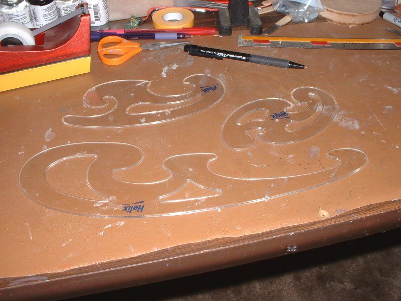
      I had taken that photo of some of the French Curve devices I had used, during the "paper half-model" stages of things. Figured I'd upload it.

      Yesterday, I tried to send in a post about other web resources, about the operational history of the CSS Manassas, etc. -- but I must have been over-doing things, yesterday, in terms of volume? That or the system didn't like the links for some reason? Dunno. Anyway, the system said that one last post from yesterday would have to wait until a moderator looked it over, and approved it. No big deal. I saved what I'd said, out of paranoia -- so, I could always reword things or make some other changes, and try again later, on sharing those web links and such.

      Meanwhile, though, I have enough of the pictures of the work on "figuring out the shape" of that very unusual bow ready to upload, so ...


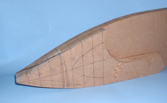
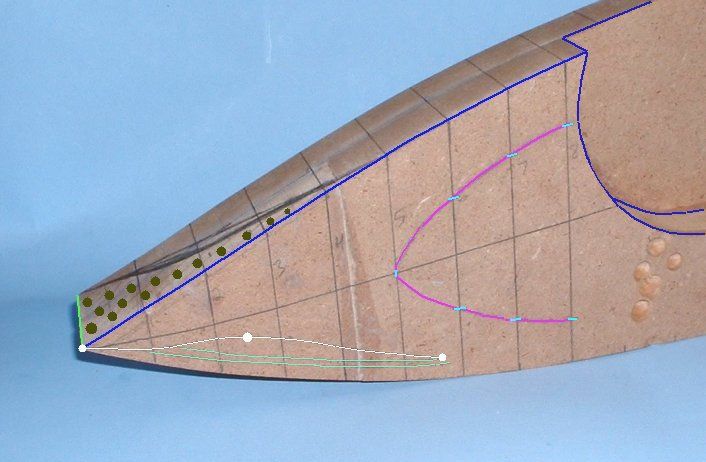
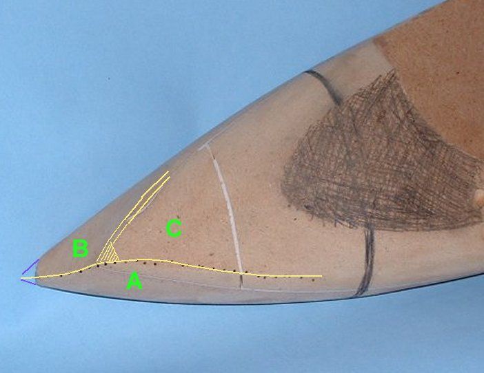
      The two pics above may not make a whole lot of sense to viewers, right away ... so, I've marked them up a bit using my old but trusty "Paint Shop Pro 5" program, on my computer. I'll upload the visually annotated versions, in a bit. And add enough words to explain what's going on.

      Comment

      • Steampunk
        Lieutenant
        • Feb 2010
        • 62

        #33
        Before I upload the annotated versions of the "bow analysis" pics, I may as well upload the few explanatory sentences I had included in the (published) "Steampunk Modeller" article. That and the comments I had uploaded, yesterday, (as part of the earlier, aborted or unpublished article's text) will explain at least part of what I was trying to do; and how I was going about that attempt. I'll fill in other details, later on. I'm more in the mood to upload pictures, right now; so I'll mostly stick with that, for this keyboard session. (It's easier on my wrists, that way!)

        (quotes on)

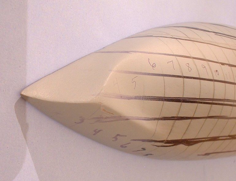
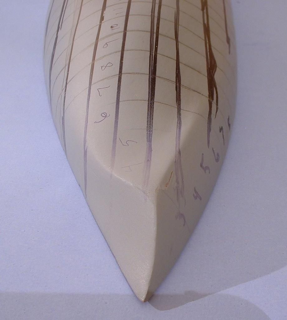
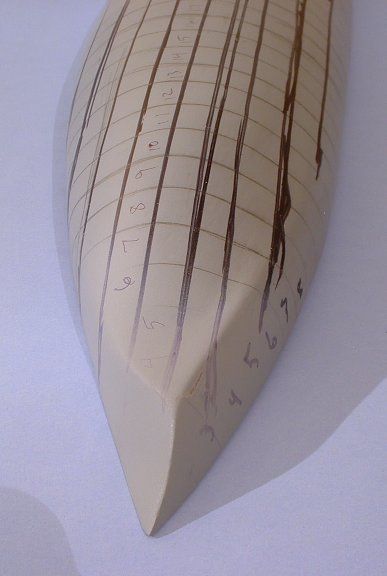
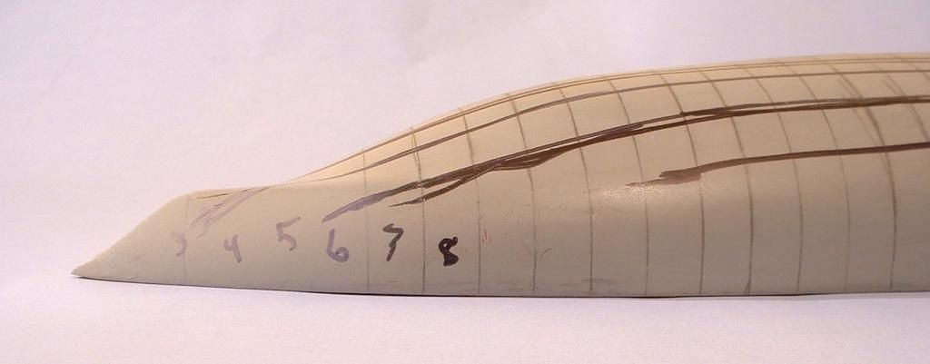
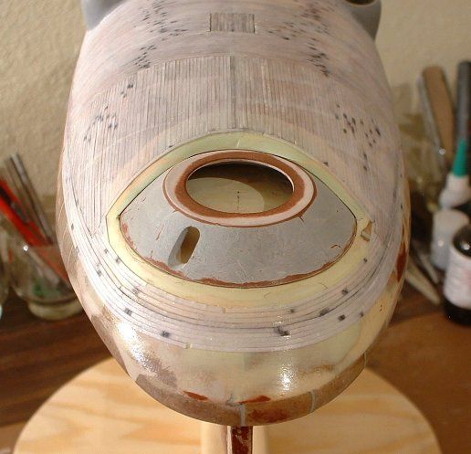
        Early drafts of this article taught me that it would take one or more full articles just to discuss the bow in the sort of detail that a nerd like me would find interesting. Suffice it to say that I used observation, analysis, and that 1861 pencil sketch to come up with the bow’s shape, as shown here. I tried, as much as possible, to have no preconceived notions. Long story short: my “Rosetta Stone” was one wavy line, drawn near the bottom of the bow. As a person with some formal artistic training, I saw certain lines on the original drawing as being, perhaps, examples of a searching line drawing technique: but one precise, double-dipping, wavy line kept bugging me. I finally had to scratch an itch and test a theory. An afternoon sanding some MDF scraps told me a lot. What had been drawn near the bottom of the bow, in that initially crude-looking drawing, was an abstracted “artist’s code” way to imply high points along important bow contours.

        (quotes off)


        Comment

        • Steampunk
          Lieutenant
          • Feb 2010
          • 62

          #34
          Largely for the sake of convenience (on both my part and reader's), I'll repeat a portion of the "Ramming Speed" sections, taken from that third part of that unpublished article I had uploaded yesterday. Just seems like it's more handy and less "jumping around," to place that explanation here, as well: where it's "right next to" the relevant images. That should serve, I hope, as a good enough explanation for the time being. I can then upload the rest of the bow-related pictures, momentarily ... without having to kill the carpal tunnel in my wrists too much, today.

          (quotes on)

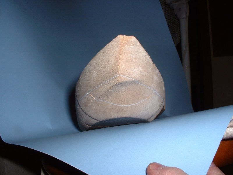
          My interpretation of these historical statements took a while, and went through some changes. The more I studied things, the better I thought I understood what it all meant. Part of that discovery process was to do what I could to “see” Chalaron’s drawing, in three dimensions: so, I built several “study models”.

          I had an intuitive hunch that one wavy line in particular, near the lower bow, was a careful but abstracted attempt to represent the “top of a hill,” where several complex contours interfaced or met. A way to show the widest points, along the sides of the bow – without showing individual cross section drawings.

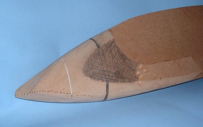
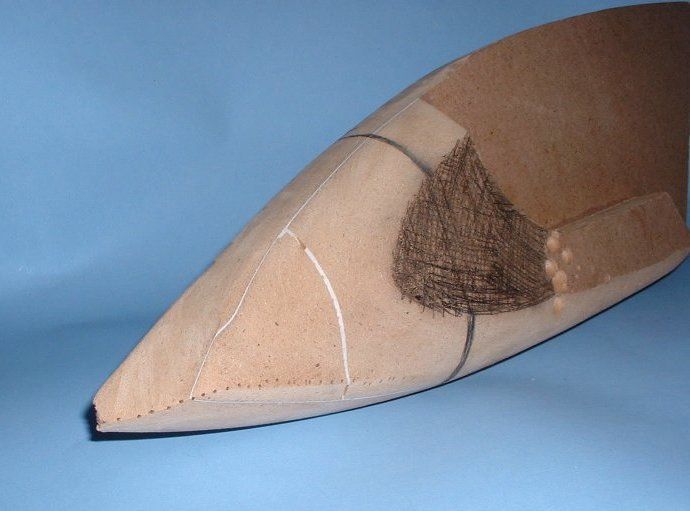
          What I found out is that if I drilled a series of small holes, to mark off that exact wavy bow line, on a solid MDF study model I had built to work out the cross sectional bow shapes, and then “connected the dots” when I shaped the areas above and below that line: several complex areas all made perfect sense.

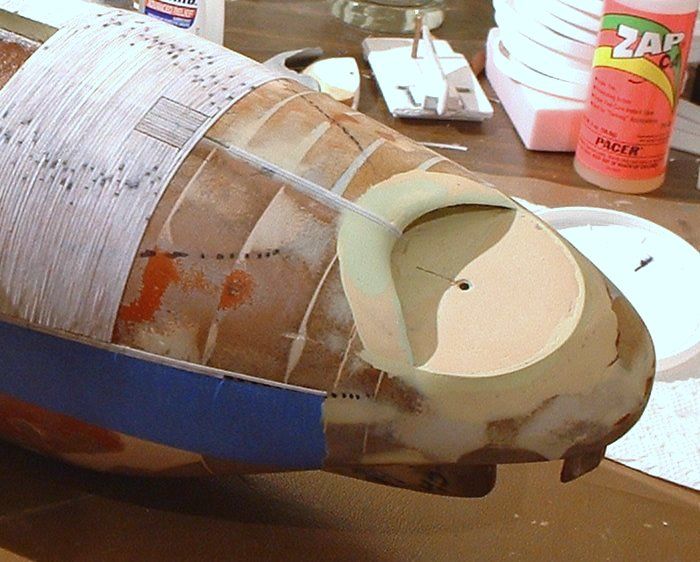
          From the bow’s ramming tip, going backwards: Chalaron’s wavy line gently dipped downwards; then gently rose back up; then did an even slower, more gentle, downwards dip. Sort of a shallow “W”. I made my study model’s lower bow convex, below Chalaron’s line. That just seemed sensible; and was a good starting point. The dipping line at the bow implied a concave shape was above that line. The dipping line behind that one was also concave above the line. Between those two, but not visible on the (modern, computerized) copy of Chalaron’s drawing, was another implied raised “interface area” or “top of a hill”.

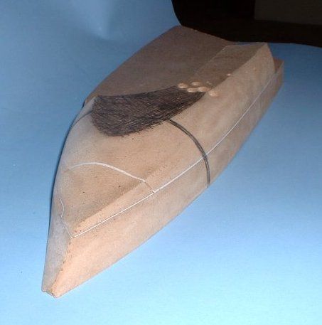
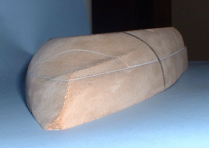
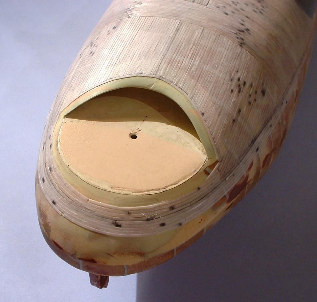
          I further presumed that the main hull’s shape was convex. I then had to figure out how to get that aft-most dip or shallow concave area to blend into the main hull, behind it. What resulted, when I came out of “right brain mode” (artistic, shape-oriented) and looked at what I’d done, resembled a sea monster’s skull. The area where the upper part of the ram blended into the main hull, almost looked like an eye socket. The bow looked “nose-like”. The wavy line almost resembled a jaw line, or row of teeth. But this wasn’t what I had in mind, when I was doing the shaping work. I was just trying to follow the “rules” Chalaron had set down on paper; and that’s what resulted.

          A very complex form! And an interesting one, visually: if only as a bonus. I was mostly concerned that the form matched Chalaron’s sketch well, and looked like something that could be built in the time period. To me, it looks like something smart folks might have come up with then, to expand on what others had done in their past: the ancient Phoenician’s or early Romans, for instance, with their oar-powered warships.

          (quotes off)

          Comment

          • Steampunk
            Lieutenant
            • Feb 2010
            • 62

            #35
            Just to explain: Part of the reason I didn't take a lot more step-by-step photos, of the process above, was that I hadn't expected it to work out as well as it did!

            I was only using random scraps of MDF; not "clean" and nice, fresh, untouched pieces of MDF or Medium Density Fiberboard. My paper half-model only got me so far, in being able to visualize the shape of the bow, where the hull sort of ended, and the "ram" took over. I had expected my first stab at interpreting that 2D drawing, into 3D form, would be a disaster ... so, I didn't waste "good" materials on it; and I made no effort to take my camera rig out into the (very dusty!) garage, to take pics as I worked on that first solid analytical model or tool.

            I had figured I would screw that one up, a lot; and would have to start over, again, a second time, before I was starting to get the hang of whatever was implied in Chalaron's drawing. If, indeed, anything at all was implied there; as I had guessed it might be. I figured that after two screwed-up MDF test models of that bow, maybe I'd "be onto something" well enough to drag the camera out, for a third test with MDF wood. (Etc., etc.) But my initial, pre-testing-theories-using-MDF-scraps guesses must not have been too far off of the mark ... because I had something I liked, the first time instead of the third. Leaving me with a situation where I had to write some notes down, quickly, before I had forgotten what I had done!

            In a sense, I guess that solid block of MDF scraps was supposed to be a "go or no go" test, of sorts.

            It was supposed to tell me that one of two things was true: either I was ONTO something, with my guesswork that Chalaron's original drawing (not the tracing) was implying high points along a specific set of features, where the mostly-solid, mostly-wooden ram and the forward section of the hull met or interfaced ... or, I was "ON" something.

            Because I didn't expect it to work out that well, on the first "get all dusty, sanding the heck out of this solid block of MDF" attempt, I had been too lazy to even centerpunch that row of drilled holes. The thin diameter drill bit wandered all over the place, as a result ... but, I figured I'd be able to "find the line" anyway, when I was sanding ... and had no guarantee my theory wasn't full of it, anyway ... so, I just pressed on.

            Anyway, here's more pics.

            These next ones will show some of the stages of work which happened, after that "Are you ONTO something, or ON something?" test; or they serve as alternate camera angles, to show the true shape I'd come up with, during that initial stab at shaping things as Chalaron had implied.


            Comment

            • Steampunk
              Lieutenant
              • Feb 2010
              • 62

              #36
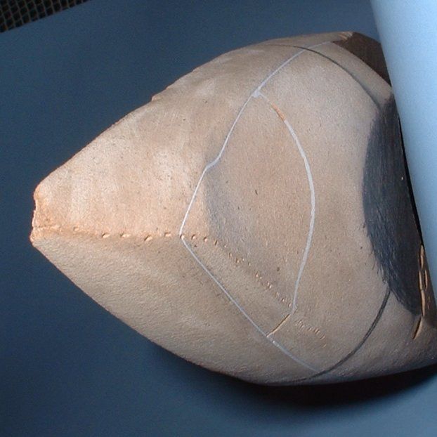
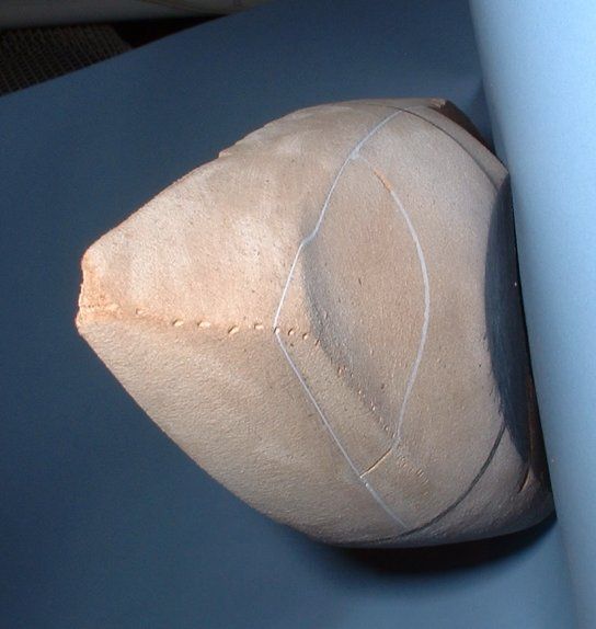
              I was getting some photos I liked -- (as seen immediately above) -- but the photos weren't showing the "drama" of that ramming device, well enough to show what I was seeing when I had the thing in my hands, and could turn it around in natural light or whatever, and study it that way. So, I played around with some ways to attempt to show the thing, more or less like someone underwater might have viewed that bow.


              Taking that shot, and some other ones like it, and rotating and cropping it, gave me images like these:


              Short story was: it was shots like those which later inspired me to think I could spice this thing up, enough, for publication in a sci-fi bookazine, just by sticking some eyes and teeth on it. Even so, I had kept that "face" fairly cartoon-like. Painting it up like a sea monster's skull would have been even cooler, and would have taken advantage of the skull-like shape this arguably turned out to be ... but, hey, what can I say. Maybe later. But with deadlines looming, I stuck with what was quick (and that I wouldn't likely screw up!) on the "final" paint job.

              Comment

              • Steampunk
                Lieutenant
                • Feb 2010
                • 62

                #37
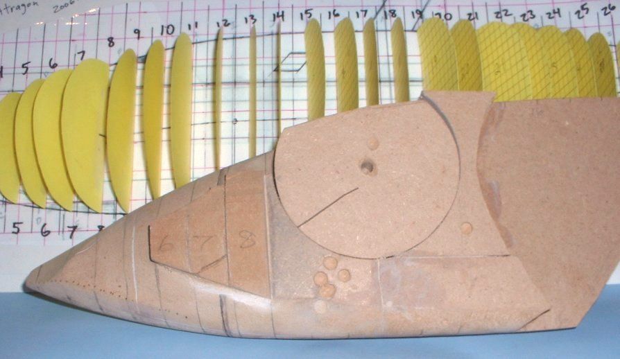
                I'll throw in one shot which shows the second phase of the "paper half-model" stages of things; and some of the early work, using MDF.


                What that shot, immediately above, told me was that, yes, I did do a second round of the "paper model" work. I had stopped where readers saw it last, with that particular paper model; and, using the improved data I'd gained from doing that work, had generated what amounts to a tracing of that work (a new side view drawing, I mean) ... and had "tape armored" that drawing, etc. ... and had generated new cross section drawings, using yellow-colored card stock or whatever. That work being intended to let me get a bit closer, without having to do much "new" work. What I mean is: I could see lots of little things I'd want to correct, all over the place, on that first paper half-model. It was easier to just trace the "old" paper cross sections onto new paper; and then do the corrections, by eye, by drawing them onto or over those "version two" tracings or whatever you want to call them ... and then, cut out the new cross sections. Tape them onto the new side-view tracing. Study them by staring at the new "half solid" model, from various angles and so on ... and then, start cutting some solid MDF sections out.

                Doing stuff this way works out well ... but you have to be able to control your desire to be overly-anal, at every step ... or you'll take forever to get anywhere! It's sort of like, at some stages, you're banging your head against a wall ... but in others, you're all "Use the force, Luke!" I don't mean that in an overly flippant way. It's just a humorous way to say that as I'm doing this, I'm consciously "flipping sides of my brain".

                The analytical left side is a very necessary component to figuring stuff out.

                But so is the right side. The artistic side. The side of your brain which was purpose-built for analyzing shapes, and what not.

                If you try to do work like this with only one side of your brain, exclusively, my feeling is that you won't get far.

                Sometimes, using the right side DOES feel a lot like "magic," or "Use the force, Luke!" ... but when your left-brain runs out of ideas on what to do, it's time to "let go of your conscious self; and act on instinct". (To steal or paraphrase an Obi-Wan'ism, from "Star Wars: A New Hope".)

                Comment

                • Steampunk
                  Lieutenant
                  • Feb 2010
                  • 62

                  #38
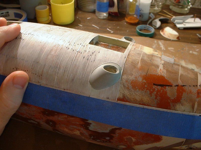
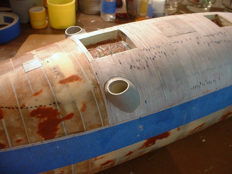
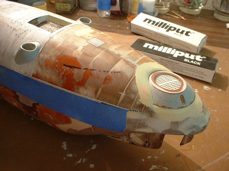
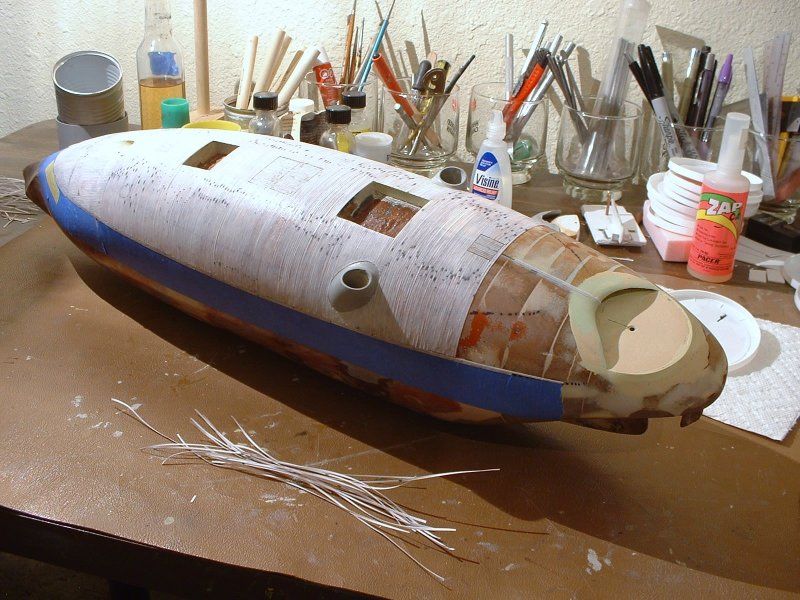
                  Four shots of the model, in primer, when it was a bit farther along ... and then, I'm gonna take a break for a while to get "real life" dealt with.


                  That last shot is probably the one that tells me I "got it right," more than the other shots. It looks like something Ancient Romans would have tried, if they had steam power instead of having to deal with oars and/or sails. And more importantly, it looks a lot like something that could have been built out of a bunch of wooden beams, stuck together in some way, and facing forward. Something do-able, within the means of a bunch of people under both time and budget pressure.

                  But the one thing that makes me think I'm not too horribly off the mark, as far as interpreting the meaning of Chalaron's 1861 pencil "blueprint," and translating what I thought I was seeing, from a 2D form into a 3D form, was this: the whole "Bowie knife" bow shape strikes me as being over-engineered, in a sense.

                  Yes, it would be remarkably strong. As designed.

                  Yes, it would have kicked major bootie, against "hollow hulled" wooden ships. No question there, either.

                  But if you try to see the bow of this thing striking, say, the USS Richmond ... I can see why, if the crew of the Manassas didn't manage to come directly in, at essentially right angles to what they were trying to punch a hole in ... yeah, I can see that bow's shape sliding sideways, and scraping anything on the exterior, completely off of the ship it was ramming!

                  And doing a lot more damage than the US Navy wanted to admit ever happened!

                  Notice that although they claim virtually no damage was done by the Manassas, during that initial attack, that the Richmond itself was pretty much all but mothballed, after that attack. Kept around, for the sake of appearance, it seemed ... but other than that, it was largely useless in combat, as far as I can tell. I'd have to find the exact quotes, again -- (maybe lurking in the ORN, or Official Records of the Navy) -- but as I recall it now, there were letters saying that the Richmond didn't steer worth a darn, after this encounter ... and was just generally a mess!

                  Despite the US Navy claiming, "That didn't hurt!" in regards to the attack by the Manassas, the reality seemed to be considerably otherwise.

                  From my reading of that recently discovered journal, kept by a US sailer on board one of the attacked ships ... the psychological damage alone was considerable. Something that heavy, moving at even a slow speed, would have transferred a LOT of energy during any collision.

                  But at the same time, the Confederates found out, to their apparent disappointment, that only a head-on collision was likely to accomplish the end goal they had initally desired. And since the Federal forces seemed to have learned that, very early on ... it wasn't likely they'd get such a chance, a second time. That said, the Manassas and the other vessels they'd rounded up, for that initial attack, DID manage to "scare off" the Federal warships for a considerable length of time. And apparently stopped them from building a battery on land; which they had desired to do.

                  Anyway ... more pics and such, later ... but for now, "Real Life" calls!

                  Comment

                  • Steampunk
                    Lieutenant
                    • Feb 2010
                    • 62

                    #39
                    Found time to upload one more picture.


                    This one, if I had been "organizee" enough, before this, probably would have counted as a Beauty Shot ... but, hey -- better late than never!

                    Comment

                    • Steampunk
                      Lieutenant
                      • Feb 2010
                      • 62

                      #40
                      I'll give it one more attempt to post an off-site link, to where you folks can see an on-going conversation regarding this boat's history:

                      http://www.civilwartalk.com/threads/...anassas.81908/

                      Hopefully, that link will cooperate? (I've tried to post it, here, before -- but the system, for some reason, didn't want it to be posted.) Being a relative newbie to both this forum, and that one, it's possible I'm just doing something wrong ... but other links "worked" over here, so ...??

                      Anyway, assuming this gets posted ... I feel that (historical research type of) conversation is well worth reading; for anyone here who is beginning to be interested in digging up more info about the Real Life, actually-existed craft.

                      I feel they've got a lot of good, solid, relevant info over there. And they keep looking for more. The idea of on-going research excites me, when it's centered on finding out more and more of the truth about bits and peices of technological history. Some of the stuff they're coming up with, over there, makes prior mentions or write-ups in historical records, obsolete in some ways.

                      For instance: virtually every after-the-war bit of visual information I've seen to date, which tries to show how the real CSS Manassas was armored, states or implies that large iron plates were used. And that's just not true! And it's been, arguably, well known that that wasn't true, for over 100 years -- but only a relative handful of the people who have studying the real thing, have taken enough time to gather up extant bits and pieces of info; and to try to use it to sort of make a "composite sketch," as it were, of how the real thing was constructed. Despite newspaper articles from the early 1900s, which made it clear that the real thing's armor wasn't large iron plates; and it wasn't the type of iron rails used today in railroad transportation, the bulk of the drawings and such that were created, to show what this thing likely looked like, show huge iron plates in use.

                      Besides the accounts in newspapers, roughly 50 years after the American Civil War, further proof making large iron plates unlikely has long existed --but was largely ignored. What I'm referring to is this: the metallurgy of the time simply wouldn't have allowed that to be the case. What was commonly done at the time this thing was first created was for much smaller-in-size metal plates to be manufactured. The larger "sheets" were considerably harder to manufacture, even in "just bent or rolled in one direction" form. The idea that armor plating which consisted of compound curves on large, armor-thickness plating, on the Manassas -- which was built in a relative hurry; and was funded via private not government sources -- all along, that should have been mostly obvious as a really "pushing it" idea. But that's what the visual record has often shown. Those who have been doing their best to sift and sort through the historical record have learned to look past that misinformation ... but there isn't any huge amount of a "push," that I'm aware of, to sort of "proofread history". What little there is, seems to be little tiny pockets, here or there; of people who are fascinated with the real-life vessel; and want to know more about it -- but want proof, before they'll believe unlikely stories.

                      Anyway, for those who have an interest in finding out more about the lateral thinking going on, 150 years ago: that other site is deserving of some of your time. Those who are extra-deep into this stuff -- (that is, want to do some actual research and thinking, themselves) -- will be fascinated by the tantalizing tidbits that are being dug up. Just as one tiny example: the folks over at that other site took photos of the type of early, relatively-primitive railroad technology that it appears was used on the real life Manassas. I'd never seen such real-world examples of what I had presumed, from those newspaper accounts, had likely been "recycled" for use as armor, when the real Manassas was constructed.
                      Ten years or so ago, as many of you readers here already know, there was a resurgence of interest in the USS Alligator. Which ended up being the subject of a DVD that's still available. (Discovery Channel, if I remember correctly, did that one. Number four in their military series, I think it was. I'd have to get my copy out and double-check that; but off-hand, that sounds about right.) My point is: people once had certain ways of thinking about certain things, which turned out to be either totally untrue, or largely untrue. And once modern people started really taking advantage of the idea that information is much easier to share, than it was 100 or more years ago: huge amounts of data suddenly came into the awareness of the people who were looking for it. And once the study started, again -- well, as they say: truth is stranger than fiction!

                      As it turns out in that case, although the USS Alligator was a little-noted historical footnote, here in the US; over in France, they still had full blueprints for that technological wonder, tucked away in their vaults, as it were. Enough info that David Merriman was commissioned to build an R/C submarine of the USS Alligator; which was then tested, in real life, in a super secretive modern facility the US Navy maintains. So, on the one hand, history in the US largely pretended the Alligator never existed ... but the truth was out there; and good research by long-time fans of old inventions dug it back up. That resulted in not only a modern DVD on the subject; but also resulted in some very impressive test results, at that US Navy facility. (But look for that DVD, to find out more about the Alligator, the easy way!) It's probably apparent, but the reason I'm talking about the Alligator, here, is that I believe the same kind of resurrection of more historical truths, based on solid science, could easily be applied to the CSS Manassas. After all, it's last known resting place has been recorded in history -- and it's not some vague notion of hundreds of square miles of ultra-deep water, or whatever. Its operational life ended in an inland river; within a certain pretty specific distance of known landmarks. Making the Manassas, arguably, a hundred or more times easier to locate. Hence my trying to get people to be more interested in the real Manassas -- since, comparatively speaking, it would be"easy pickings" to locate the real thing, and study it.
                      Last edited by Steampunk; 08-04-2014, 12:33 PM. Reason: minor typo

                      Comment

                      • greenman407
                        Admiral
                        • Feb 2009
                        • 7530

                        #41
                        Good link, lots of good stuff there.
                        IT TAKES GREAT INTELLIGENCE TO FAKE SUCH STUPIDITY!

                        Comment

                        • Steampunk
                          Lieutenant
                          • Feb 2010
                          • 62

                          #42
                          Okay. Finally! I'm ready for another update. Over the last several days, I've been going through many old photos, and getting things "organizee". That took forever, and it isn't even completely done yet ... but, I have almost two dozen new pics ready to upload and explain.

                          You'll notice, as you look through these pics, that I'm "jumping forward" quite a bit. I'll come back, sometime later, to do things like show how (and sometimes why) I did what I did, to create the main hull shapes and so forth. But before I figure out which of the hull-creation photos are necessary to explain things, adequately enough: here's something some folks -- (such as the guys over on the "Aye Candy: CSS Manassas" thread, over on the Civil War Talk web forums) -- are likely to be far more interested in.

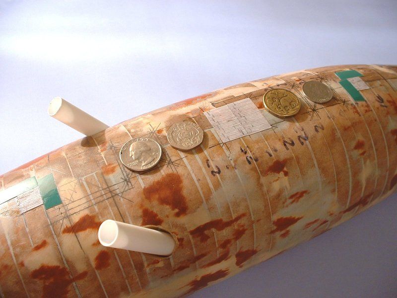
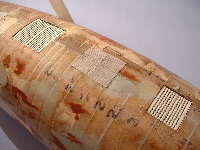
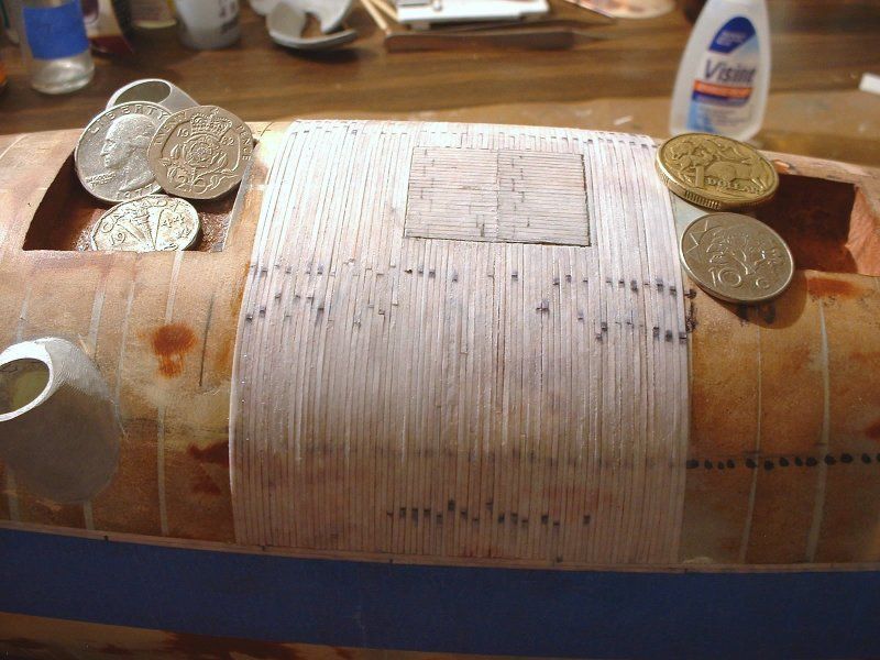
                          Specifically, how I managed to simulate "flat street car iron" being bent over and around this compound, wooden shape: to be used as armor!

                          First step: Try some ideas out, to see if they're going to work at all. Partly to get a good idea of how it would all look, when I'm done.

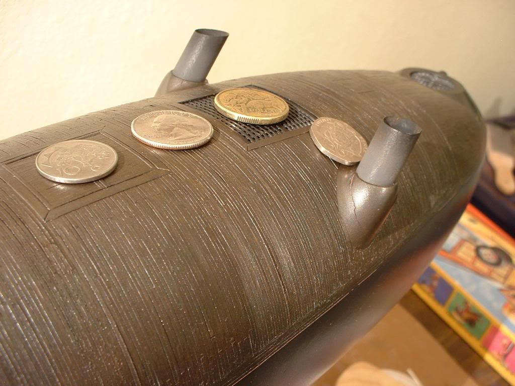
                          There would be no sense in doing things in the labor-intensive way I had planned to, if, when the final paint was applied, you couldn't really see any difference in the "texture" of the areas I was going to paper-clad. But as you can see: even with flat black paint applied, the iron bands or stripes can be seen for what they are. The spaces between each peice of paper didn't "go away" during the glueing process ... etc., etc. ... and all it looked like it would take to bring out some of the feeling of these bands being "metal" was going to be rubbing some graphite over the flat black paint. (Thereby giving it a subtle but evident sheen: just enough to emphasize highlights, if the available lighting hit it just right.) In the end, I did more than that: using metallic paints, with no attempt at making the upper armor look like part of the "black devil" that some historical documents colourfully called the real-life CSS Manassas.


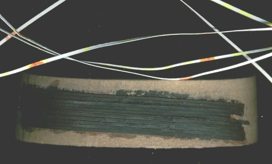
                          You'll see better images, as we progress along ... but what that picture shows is ordinary card stock type of paper, which had been cut into very thin-width strips, after they had been glued down (with the very thin-viscosity "Pink-label" Zap CA glue) onto a leftover "slice" of MDF (or Medium Density Fiberboard). That MDF "slice" or section having been cut and angled and shaped, just as if it were a legit (instead of spare or leftover) cross section of the hull.

                          I should probably mention that this work was all done, several months before the actual need for this work -- partly in hopes that I'd come up with some less-labor-intensive way of doing things, when I DID get to that point. But as it turns out: no such idea was forthcoming, so, in the end, what it took was biting the bullet, and using up a week of "vacation time" (for lack of a better way to describe it) doing very tedious WORK! As with a lot of things in this hobby, though: if you want the end result to look really unusual / interesting, sometimes the only thing to do is just get it done, however you need to. Even when it's incredibly tedious, at the time you're sitting there and doing it, sometimes, there's no easier way or more exciting way. So, you do what'cha gotta do!

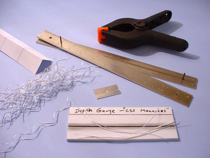
                          Here's a visual idea of how each of the paper strips were cut:


                          I'll cheat a bit, and explain what's going on, via some quotes from that published article ... showing first the "why," and then the "how".

                          (Quotes ON)

                          THE TURTLE’S SHELL

                          “A shield, or roof, was put over the deck in the shape of a whale back.” (A later reprint from the New York Times used the term turtle back – or so one copy makes it appear.) “The frames were eight inches thick, moulding way – that is, solid against each other crossways from forward to aft, and the planking on top of this was four inches thick. Outside of this she was covered with a single layer of flat street car iron, such as was used at that time to run the street cars on - not rails such as are used now.”

                          This unusual iron-cladding or armoring process interested me quite a bit. I had previously researched another ACW “infernal machine,” and had run across the idea that the metallurgy of the early 1800s wasn’t good enough to produce large iron plates. Peetz makes it clear the Manassas was largely made of wood, structurally-speaking. It was then covered with what might be thought of as an outer layer of iron “planks”. Quite a clever idea. It would have been a great intermediate step from all-wooden ship building, towards all-iron ship building. Technical people with lots of training wouldn’t feel lost, or like they had to start over. It would all be do-able, “today,” without delay. And if it worked, other Southerners could also quickly do the same thing: quickly creating an ultra-modern navy. (And in the process, arguably forcing the US to build the Monitor, to be able to counter-act Southern boats like this one.)

                          I tried to get a solid idea of exactly how wide, long, and thick each of Peetz’s iron “planks” would have been. No one really knew with the type of precision we scale modellers hope for. Daniel Pete of the Southern Museum of Civil War and Locomotive History and I had traded several e-mails. He passed on my “flat street car iron” questions. Museum Curator Michael Bearrow’s reply was that, "Iron and rail were often locally produced and/or imported very much adhoc." Which broke my temporary paralysis. That being the case, I felt I couldn’t go too far wrong just by going out and getting width measurements from things like mine car tracks – assuming that would be about as close to early 1800s street car wheel widths as I was likely to find.


                          CLADDING WITH PAPER PLANKS

                          I set up a homemade strip-cutting system that would allow me to create many same-size “iron planks”. My model is built in 1:48 scale, and I was aiming at planks two scale inches wide by eight scale feet long. The latter was easy: a 4” x 6” index card measured three planks long. Cutting the strips to two scale inches was another matter. (There was no way on earth I was going to try to scribe all those lines onto the final model! Pick your battles, says I! And for the same reason, I totally ignored making rivets.)

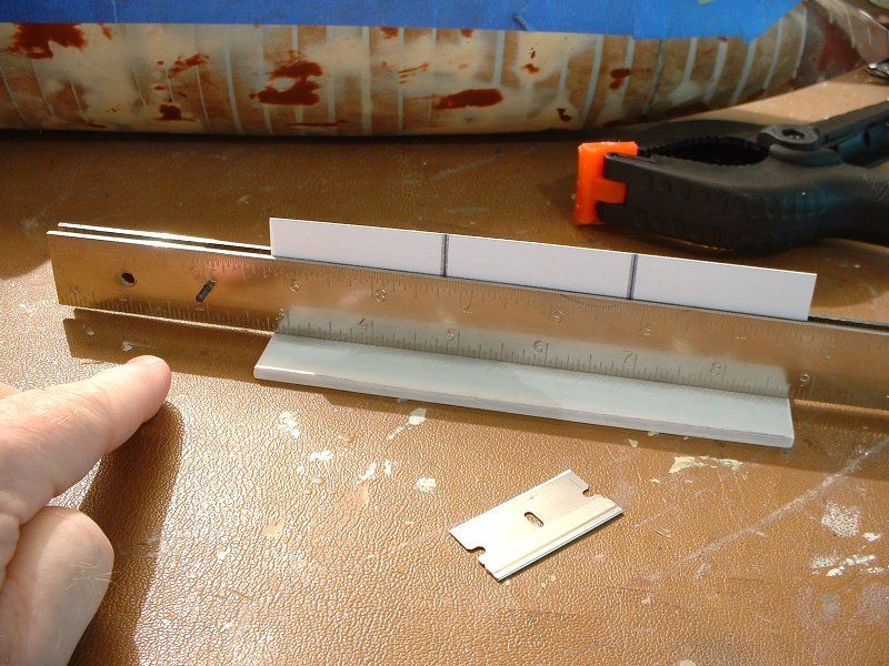
                          To cut the very thin strips, I had to make two tools. One was a pair of metal rulers, which I had modified so they could be held together tightly and in proper alignment, with minimal hassle. Clamping them into a vise and drilling two holes (one in each end) and then putting a cut-off piece of that drill bit in each hole, sufficed nicely to make that tool. The second tool was a depth gauge of sorts. One flat piece of sheet plastic (as a valley floor) had two other pieces of sheet plastic glued to it; with a trench running between them. The thickness of the two upper sheets set the proper depth. The paper was allowed to drop between the two rulers, and to rest on the floor; while the ruler’s edges were held up by the two plastic sheets. I could use a clamp to hold one end of the two rulers together; and my hand to clamp the other end. I ran a razor blade along the two metal rulers ... and if I held everything steady, I got a very thin, nicely parallel paper strip for my troubles. As a time-saver, I had scored the index card into thirds: thereby making three connected planks, from every strip.

                          The application of the many simulated iron planks took me a solid week. What I did was to use a rounded (#10, general purpose) X-acto blade to pick up small drops of Zap CA super glue. (The water thin type; not the gel type). I positioned each new strip; held it down with one hand; applied a drop of glue on top of each strip with the other hand; it soaked through the paper and stuck the paper down; and hardened the paper, when it set. I then repeated that, an awful lot of times! (And no, I’m not trying to belittle or demean the metal-working skills of anyone who worked to reconstruct the real thing. Assume any errors in planking were caused or amplified by the carpal tunnel in my aging wrists; my aging eyes; not to mention fingers that felt like they had glass gloves on, after a while, from all of the dried super glue on my fingers!)

                          Although it was tedious work, I felt it was well worth it. I had wanted to know what the real Manassas most likely looked like – and now I have a much better image. And a new respect for people whose hobby involves precisely cutting wood, to plank large ship models. As a bonus, I understand why residents of New Orleans, who had apparently seen the real thing being reconstructed in dry dock, had called it the turtle. Assuming it was only armored along the surfaces that would stick up out of the water; and if it had a compound curvature to that upper hull, then the armor plating on top would indeed resemble a turtle’s shell.


                          (Quotes OFF)


                          I'll just quickly mention, in passing, that that's the final-final version of that published article's text: as I had submitted it. Andy Pearson, the editor for the various special issues published by "Sci-Fi & Fantasy Modeller," does a fine job of surgically removing off-topic tangents and the like, when I submit article copy which is really pushing things, in terms of overall length. (Which is arguably almost always!?) But, give or take a few words: that's "as published".
                          Last edited by Steampunk; 08-09-2014, 02:50 AM. Reason: minor additions and alterations, here and there

                          Comment

                          • Steampunk
                            Lieutenant
                            • Feb 2010
                            • 62

                            #43
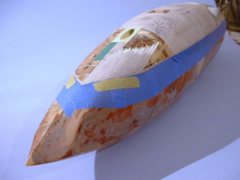
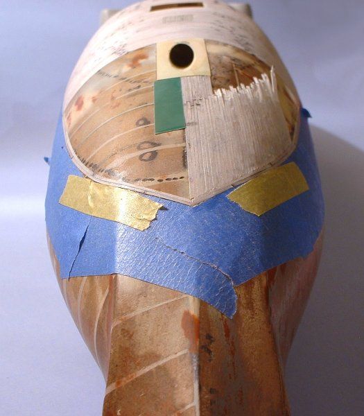
                            I'll try to "write short" for a change ... and mostly just post pictures, for now ... but I'll explain some high points of the how-to, later on, if it feels like it's necessary.

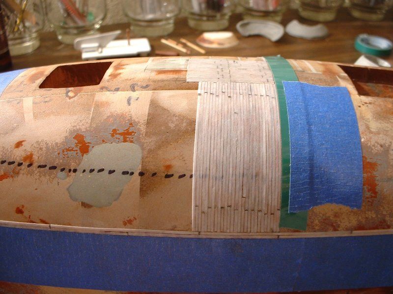
                            For now, one of the main things I'll point out is that, to get started in some area or other, I often used "Dymo Label Tape" as a hard, "tall," self-adhesive straight edge. (Sometimes reinforced with masking tape, in large areas; or areas with a highly curving surfaces under them. Better paranoid than sorry, I always say! And I definitely did not want my straight edges or guides popping up and off, in the middle of this work. And it felt like they just might, so ...)

                            And yes, every single "iron plank" had to be cut to length, one by one: to fit into the specific area it was being glued onto.

                            To cheat things, a bit, you'll note where some "fake" panel lines were scored into the sheets, prior to cutting planks out ... but it's still very tedious work! The kind of work where your fellow scale modellers might award you some serious Martyr Points (tm) once they know what you did ... but, hey, I really wanted to be able to see, right in front of me, the sense of what an all-wooden vessel of this shape would have looked like, with very unusual, early-war armor on it.

                            The finger, seen in the shot immediately below, is pointing to the cut-off drill bits I used in the two drilled holes I had mentioned (in the quotes, above). The drill bits were used to keep the two rulers properly aligned with one another: but at the same time, I could easily spread the rules apart, or tightly clamp them together: smoothly and without much hassle. Which was very much necessary, for my sanity if nothing else: since I had to just keep on doing and doing it.


                            (Photo below.) Not wanting to have to figure out where hatches and the like should go, way too late into the overall process, I started the overall process by adding those features; and adding things like the "circle" at the lower edge of the turtle's iron armor. That greatly cut the mental part of the workload, way down: by giving me definite starting and stopping points. Which made cutting "planks" to length, easier and less prone to mis-measurements and general stupidity on my part. You'll see what I mean, as I post the rest of the in-progess pictures.


                            (And believe it or not, what you just saw, above, took up an entire day's work! Things move vveeerrrrryyy slowly, with strips this skinny! Especially when you are doing some critical "layout" work, that will determine how easy later work can be done. Figuring out how best to do those two horizontal strips, all around the circumference or whatever, took some heavy figuring and playing around with paper strips -- basically dry fitting and testing positions, and so forth.)
                            Last edited by Steampunk; 08-09-2014, 03:18 AM. Reason: mostly just minor re-wording and such

                            Comment

                            • Steampunk
                              Lieutenant
                              • Feb 2010
                              • 62

                              #44
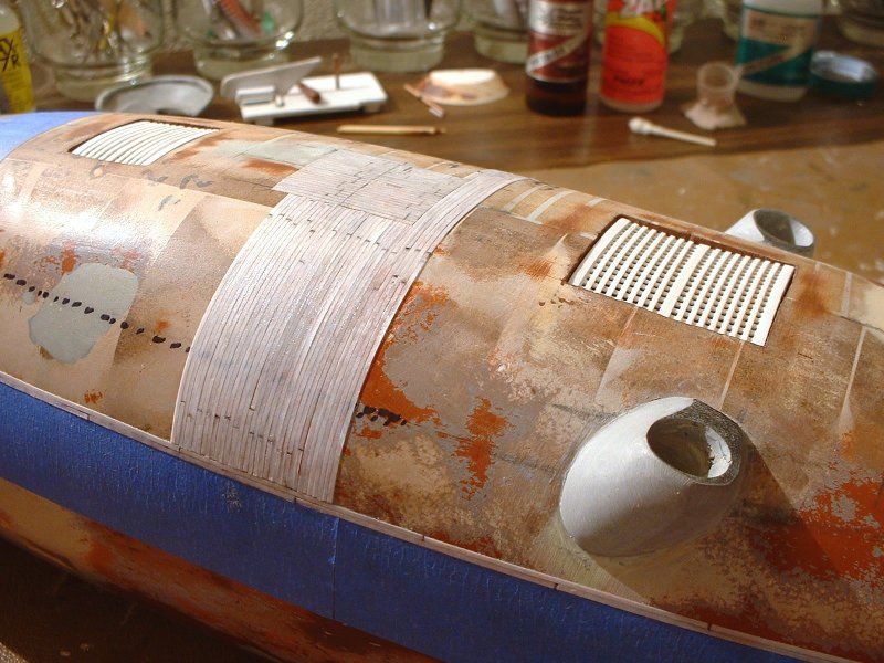
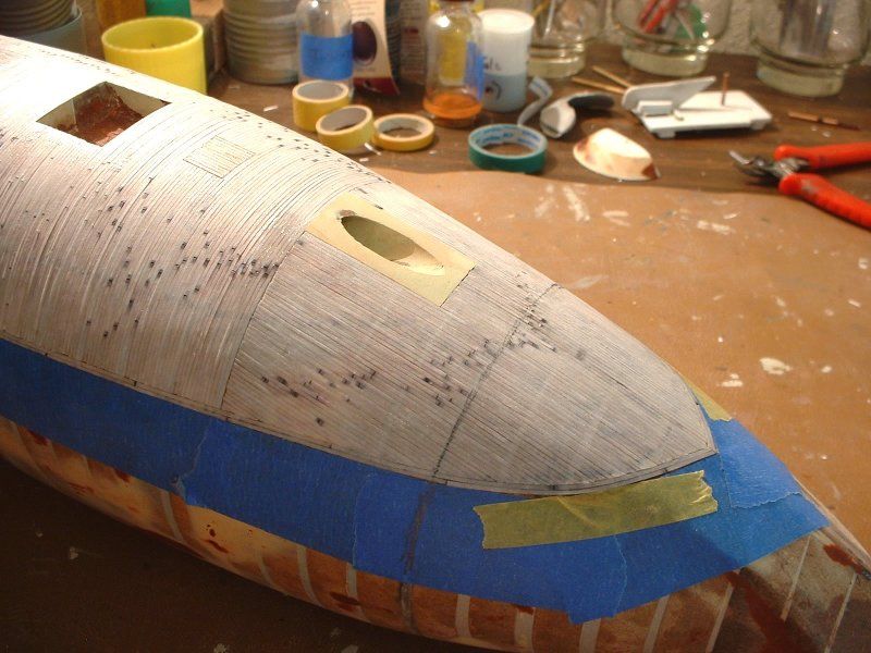
                              Moving into other areas of the hull; but using the same repetitive technique, over and over and ...


                              Note the use of Dymo Label Tape, in the shots above. (The green rectangles.) I used it to make that armored tube for the cannon, as well. That and a fat drill bit, turned shank-end-in. Rubbed some of the great "Butcher's Bowling Alley Wax" on the drill bit, and applied auto body "icing" around all that. (Which work I'll show, later on, when I get back to a semi-linear "start at the beginning of the hull's creation" stuff.)

                              Dymo is great for setting a hard, straight edge on a specific spot on the hull. Once you have, say, four or five "iron planks" glued side-by-side, you could probably safely remove the tape guides. I left it on there, specifically for the photos: so my "cheating" methods would be evident.


                              (About the time I was to this point, I had begun to start thinking of this thing as the "CSS Wickerclad" ... which shows my mind was mush!?)

                              Comment

                              • Steampunk
                                Lieutenant
                                • Feb 2010
                                • 62

                                #45
                                Something I should point out, which is not a "how to" sort of thing, but that may interest fans of the real-life Manassas: as I had worked on the hull itself, I was able to transfer some of the "datum lines" or what not, from the 2D drawings I had come up with; onto the model's 3D form.

                                As I began to work on the armoring process, I wanted to get an idea of what would be positioned where, in terms of visibility during combat, etc.

                                Hopefully, I haven't stayed up past my bedtime too much; and am not making a total mess of this explanation ... but here goes, anyway.

                                I mention those lines or rings drawn onto the upper hull areas, to explain that I guessed there would be two seperate "water lines". I felt the drawing by J.A. Chalaron had indicated a six-foot tall freeboard was the "maximum height visible, out of the water" sort of situation.

                                I had assumed the armor would be a bit lower than the water's surface: but probably not TOO much lower. I guessed at, say, a scale foot of "extra" armor depth, below that "six foot of freeboard" point ... and that's more or less where I had located the lower edge of the iron planks.

                                When I first built this thing, I didn't have one hundred percent proof that the real Manassas ever had a functioning water ballast system: to adjust the vessel's freeboard, or height out of the water. I felt it likely had one; but didn't expect to find proof. Very recently, however, thanks to the excellent research being done by the people who have been hitting the books, and digging up old records, and also comparing notes, for several years now (that I know of; and possibly longer) -- see the discussions over on the Civil War Talk forums -- the presence of such a water ballast system has now been absolutely proven. Turns out that it had one, even before the war!
                                Having suspected, from close readings of the various texts on the subject of the Real Thing, that the historical CSS Manassas could likely adjust its height out of the water, and having noted that some accounts said that only something ridiculously small, like two and a half feet, was all that was visible (during combat situations) ... I fudged that number, a bit; called it three foot; and marked a second "waterline" at that height, from the top of the vessel. The fat, dark, dotted lines you see about halfway up, from the armor's lower edge: that's the line I mean.


                                The reason I'm going to such lengths to explain THAT situation, instead of just shutting up and letting the pics explain things, is that I had used that "two different freeboard heights" idea, when I had positioned the smokestacks along the sides; the turret in back, and so forth.

                                Which means that, if this model was a true representation of the real thing, and this thing was sitting in a quiet, friendly port, than it would be possible to see that turret, in back. Which might be just enough of a deterent, or so I had pictured things, to keep boarders away and so on -- should someone want to sneak up on this thing, from what (during combat situations) might seem to be the very vulnerable, unprotected aft end. However, during combat, if the river conditions (depth) allowed it, only three foot or so would be above water ... making it seem that no protection of any kind was planned or built, in the aft end of this thing. Which might (key word!) explain why there were so many radical differences in various texts: as to whether the real CSS Manassas ever had a second gun, mounted somehow in the aft end of this thing.


                                While I realize that a rotating turret is on the extreme side of historical interpretation, the idea of the shape (upper outline) of the aft end (as defined well in J.A. Chalaron's dockside drawing from 1861; and copied as literally as possible, on my model), when combined with the idea of a variable freeboard, would mean that even an "aiming straight back" cannon, in some sort of minimal cupola or whatever, would be possible, in terms of interpreting that primary source document ... while also potentially going a long way towards explaining conflicts in text records, etc.

                                I'll include one image of the aft end, for now -- (and more, probably, way later on) --with the model's turret removed. You can likely "see" how the side-view or "profile" drawing's curving lines in that area could allow for something to be facing backwards, if they had wanted to do that. Or, if you were inclined to believe that the aft end was essentially smooth and featureless ... you can visually just "fill in that hole" to see it.


                                If I had built this model as a strict attempt at a "historical" model, I probably would have left the turret off.

                                As a sci-fi and fantasy modeller, it felt like it very much belonged!

                                Not because I wanted it to be there, and was "forcing" it to be there, by "drawing outside the lines," with my model ... but because I wanted to build what I felt was the extreme end of a strict interpretation of Chalaron's 1861 drawing. And Chalaron didn't seem to be drawing a single, continuous line, back there.

                                Right from the start, I felt that something was being indicated, that was outside the norm, in that area of the drawing ... and it looked potentially a bit like, maybe, they were planning on some sort of a pivoting or rotating, protected gun, back there ... and what my intent was, right from the start, was to build that part of the model in such a way that if you overlaid the fan-made blueprints I had drawn up (and built my model from) over Chalaron's drawing, most of the historical drawing would line up, exactly as-was. There was something unusual back there ... and I had to scratch the itch of seeing it if was a turret!

                                As I will attempt to show, at a later time: even having built what Chalaron drew, back there, didn't limit the idea of a turret being "orthographically possible". In fact, once I had it built and installed, it not only was a close match for what I saw in Chalaron's side view drawing; but it could rotate a full 180 degrees!

                                The danger of trying to interpret something that was as radical as the Manassas was, for its time, with absolutely minimal primary source material, is that you're always running the risk that some part of your audience may think you're "on something". However, a different audience might think you're "onto something". There's a fine line between those two extremes! But in terms of interpreting the orthographic profile-view drawing Chalaron did in 1861: it's possible. My interpretation, in 3D, didn't radically alter the 2D source document.

                                Is it likely there was a turret (or gun) back there? Who knows!?! The argument, I suppose, is that the model builder is "onto something" ... but the real-life vessel's designers were "on something"! (Or, to put it more respectfully: had done what people like Peetz had said they had done: put much thought into it!)
                                Last edited by Steampunk; 08-09-2014, 04:52 AM. Reason: typos, etc.

                                Comment

                                Working...