CSS Manassas -aka- Steam Atragon

Collapse
X
 
  • Time
  • Show
Clear All
new posts
  • Steampunk
    Lieutenant
    • Feb 2010
    • 62

    CSS Manassas -aka- Steam Atragon

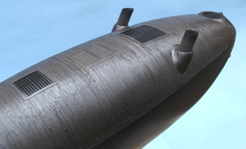
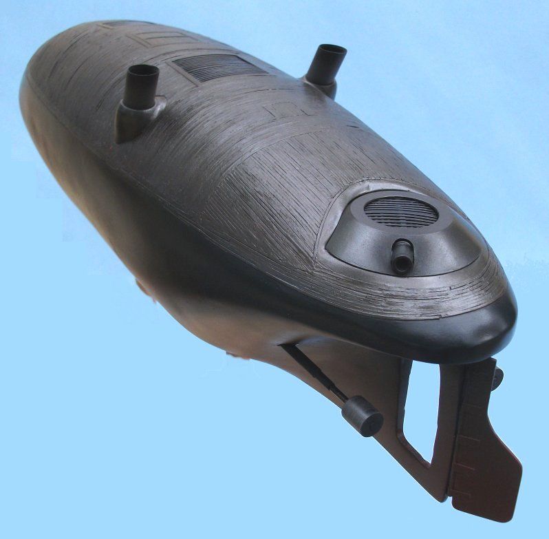
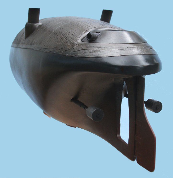
    I usually over-do the word count on most of my posts, so I'll reverse that trend here ... and will just let eight pics speak for themselves:


    The good news is ... if you want to build one of these river monsters for yourself, I've also uploaded the full set of working drawings to these forums. (Which I can do, since I'm the one who drew them up in the first place.) You can grab all of that info at the link below:

    http://forum.sub-driver.com/showthre...by-Ward-Shrake)
  • greenman407
    Admiral
    • Feb 2009
    • 7530

    #2
    You caught my attention Ward. Really nice, a modern Monitor. Looks like dual smoke stacks. That probably means dual steam engines. May I ask , If you plan on making the "more fun kind"? One engine for each shaft. If not , do you have plans to offer hulls for sale? Just asking.
    IT TAKES GREAT INTELLIGENCE TO FAKE SUCH STUPIDITY!

    Comment

    • greenman407
      Admiral
      • Feb 2009
      • 7530

      #3
      So the slot forward above the waterline, pointing forward is some kinda gun, I assume? 18" Naval artillery no doubt. Armour piercing and General purpose. Or Japanese Long Lance torpedo tube.
      IT TAKES GREAT INTELLIGENCE TO FAKE SUCH STUPIDITY!

      Comment

      • Steampunk
        Lieutenant
        • Feb 2010
        • 62

        #4
        Thanks much for the compliments! Appreciated!

        I'll add more details as to what's supposed to be what, as far as things like that "cannon in an armored tube" sorta thing, a bit later ... but for now, know that this isn't totally fictional. I took a dockside drawing from 1861, a few years back, and did my best to interpret it in an orthographically valid way ... and came up with what you see, above. I may have mis-guessed in a huge variety of ways (given how little info I had to work with, etc.!) if one compares the model I made, to the original boat ... but since no one has yet seen anything but vague sketches and drawings of the "real thing," I'd say that just looking at what I'd started with, vs. the model seen above: I feel the model is one orthographically valid interpretation of J.A. Chalaron's original "blueprint" of the CSS Manassas.

        (But the short answer to your specific question is: yeah, that's supposed to be a forward-facing-only cannon's armored living quarters. A normal-sized cannon wasn't very likely, in that turret in back ... but if you had a carronade in there, and treated it kind of like a "one shot wonder," and didn't try to stay inside the turret itself, when firing that weapon ... technically, I think the technology of the time would have allowed 180-degree rotation; and a limited firing capability.)

        Getting to the big question:

        I personally have no intention of creating a hull kit, for sale to others ... BUT that doesn't mean others won't give it a shot, at some point down the road. Just depends on how cool other people think the design is; and how badly other people want to have something like this, patrolling their local pools and ponds.

        By putting a full "blueprint" set of drawings up, in another thread -- (see link above, right below the pictures; or the one a bit below this paragraph) -- my intent was to go out of my way to make it easy for other folks to duplicate this model (or build something like it), in any scale they wish. And if someone does that, and then sells copies of the parts they created themselves, to other fans of R/C models, I'm not gonna whine about it. I posted the drawings, HOPING they'd get used by some folks around here! (Either as a one-off, or possibly as some sort of a kit effort.) It would be cool if others credited whatever work they feel I've done, if they make a kit closely based on this thing ... but, ultimately, whenever you upload something like a full drawing set to a public forum, some might use it with no thought of crediting prior work. It didn't feel like that much of a risk, to me, either way. The drawings are just sitting on my hard drive, anyway ... so, why not share them a bit? Especially since build threads have some chance of resulting, down the road! I think it'd be kinda cool, seeing others building stuff from drawings I created.

        Take a good look at the supplied drawing set, folks, before any of you assume it'd be too much work to duplicate what I've done, in the pics above.

        http://forum.sub-driver.com/showthre...by-Ward-Shrake)

        Even if a person hasn't really built much of anything from blueprints, before, I'd argue that with this set of drawings that I recently uploaded, it's quite a bit easier to build something from this drawing set, than is usually the case. The reason for that being: in my experience, Merriman's a very motivating mentor. And not likely to put up with slackers, if he thinks they can be coaxed into doing more than they think they can. So, a few years back, in some Top Secret training sessions he was kind enough to engage in, his answers and pushes really sold me on the utility of having as many carefully-defined cross sections as can be squeezed into any given drawing set. Having been well and properly convinced of just how much head-scratching and needless work such a drawing set can save a builder, I've been going ballistic in defining many more cross sections than is the norm, with every set of working drawings I've generated since then!

        Taking it a step farther: careful study will show I space each sectional drawing out, at exactly even intervals -- so, once you cut out a bunch of sections, you can treat them almost like "slices of bread". Just cut each "slice" out, using sheets of something that is as thick as the drawing's spacing. Line those "slices of bread" up, back to back to back, until they make a full "loaf of bread" ... and you'll find 90% of the shaping work is done for you, in those few easy steps. From there, it's just a bit of eyeballing and some carefully planned sanding (to eliminate the "stair steps" along each slice's "crust" area) and then some fiberglass layered over top of all that ... and you would have some useful hull halves to play with, and R/C to your heart's content.

        Keep in mind, too, that while this crazy thing just begs to be a full submersible, that the original CSS Manassas wasn't. There's considerable evidence in the historical records of the day that say it could change it's freeboard at will, via water ballast and such ... but if a person was trying to cut complication way, way down, they could build their model as a surface skimmer instead of a submarine. Leaving just that armored portion, visible up there in the sunshine.

        Having been a student of Merriman's for some years now, and studying his Cabal Reports in detail for a long time, and reading threads here, etc., I'd say that many of you could build a copy of this thing, with considerably less "blueprint" information ... and seeing how helpful I've tried to make the full drawing set, some of you might consider something like this to be a light-duty, fun, no-big-headaches, "in-between serious projects" sort of build. Heck, if folks here were interested enough in it, I'd bet someone out there could crank something like this hull's shape out before the summer's over, and the cold weather begins to set in?!? Anyone out there up for the challenge of seeing if you can crank one of these out, before the annual end-of-summer get-togethers take place?!?
        Last edited by Steampunk; 07-31-2014, 02:44 AM. Reason: typos and such

        Comment

        • Steampunk
          Lieutenant
          • Feb 2010
          • 62

          #5
          Okay, here goes with this becoming an actual Build Thread ... in a more usual, "start at the beginning" sort of way.

          Here's the historical drawing I had started with, to draw up my own blueprints ... and testing some theories as I went, using a "half model" ... eventually ending up with the static model seen above.


          ... and here is a tracing that someone made, of that official drawing. For several reasons I'll explain later, in some detail (in both words and via pictures), I felt the "several decades after the fact" tracing below was considerably less reliable than the original drawing, above.

          Basically, I noted that this drawing below existed, and I did study it (along with anything else I found) ... but when it came time to get serious about figuring out the proportions, outlines, and contours of the "real thing" I immediately went back to the image, above.


          These two drawings, plus some very interesting text accounts, I had sourced from an official U.S. Navy historical web site ... so they're as "official" a pair of drawings as anyone is likely to run across. And given that the first one was drawn by an eyewitness, who saw the real thing OUT of the water, while it was being reconstructed in dry dock ... well, to me, considering how "iffy" most of the other, later artist's takes on this thing generally seemed to be ... well, while I eagerly studied any contemporary (or later) drawings I could find, I kept coming back to that first drawing; over and over and over. When the initial "study all the images you can find" period ended, I used that drawing almost exclusively; as I felt virtually everything else was just too prone to guesswork and "making things up". Anyway ... more on the analysis phase, in just a bit!

          Comment

          • Steampunk
            Lieutenant
            • Feb 2010
            • 62

            #6
            For what it's worth: for me, this was a multi-year project. In looking at file-creation dates on photos and drawings and what not, related to the first stuff I had begun to collect, it looks like I was getting very interested in this project, by sometime in 2008 ... or possibly a bit before that. I got pretty serious about figuring out what others knew, and what I could figure out, based on that info ... but Real Life and other stuff got in the way, before too long; and I didn't build a complete model of this subject until considerably later. By 2010 or thereabouts I felt I had enough info -- (both downloaded, or bought, or created through analytical work I had done) -- to create a model of this thing.

            Part of my motivation to get serious about building that "complete" (rather than partial, for analytical purposes only) model was that the publishers I write for, out of England, were wanting to try a "Steampunk Modeller" special issue at that time. They had asked me, and their other writers, if we had any interest in that sort of thing; and if we might want to contribute something to an introductory volume with that title. I was all stoked about it, and dusted off my prior research data, analytical work, and test peices. I kind of wondered at that point, if I'd just end up building a second model of this subject, way down the road -- (if other info later appeared) -- but decided I'd be so excited, if such info did later appear, that making a second model of this subject wouldn't be anything traumatic. Work, yes ... but probably fun work.

            In some brief "figuring out what we're gonna do" discussions with Andy Pearson, the editor for that publisher's Special Issues, he took my word for it that the shape of what I felt the real thing looked like, as described in that original drawing above, was crazy enough that most people were going to think I'd just made it up, out of thin air ... and I offered, just in case a "serious" model of the "real thing" wasn't a perfect fit for that issue, to spice things up just a bit: mostly by painting some totally-fictional eyes and teeth on the final model. Which Andy approved. So, I had my motivation to complete a model of this thing ... and had managed to

            The balancing act went something like this: it appeared that I needed to sort of "science fiction" this model up a bit -- but just a bit! -- for publication in that special issue of "Sci-Fi & Fantasy Modeller". However, 95% of my interest in making a model of this subject was wanting to see a representation of "the real thing" ... as intellectually honest and as carefully "scientific" as I could make it.

            To prove that I wasn't just making this whole design up, from whole cloth, I'll show some of the analytical work I did, prior to model-building.


            (That's one drawing set, above. That's another, immediately below. Didn't want to make it seem like that's all "on one page".)


            As many folks here probably already figured out, from the two modified versions of that historical drawing, above: the first major thing I wanted to do was to see how self-consistent that drawing was; and thus, how much I could trust it as a "blueprint" rather than a sketch.

            Short story on that work is that I was deeply impressed! And very excited!

            After a bunch of careful measurements and cross-checking various parts of that drawing against the other parts, I was convinced that the original artist clearly understood the principles of orthographic drawing; and had a very careful eye and hand. I've seen modern, published blueprints or working drawings that had far more "head scratching" (or object throwing) moments, than anything I found in Chalaron's work.

            Moving on ...

            Once I had (very carefully, and without altering the "aspect ratios" of anything) enlarged that single almost-acorn-shaped cross section drawing, using a 2D paint program and a personal computer, that sectional example matched the size of the "profile view" ... (and I'll make it more clear why that was a hugely important thing, in future posts here) ... more analytical work ensued ... as shown or implied, below.


            More later!
            Last edited by Steampunk; 08-01-2014, 03:05 AM.

            Comment

            • greenman407
              Admiral
              • Feb 2009
              • 7530

              #7
              Watching with great interest Ward.
              IT TAKES GREAT INTELLIGENCE TO FAKE SUCH STUPIDITY!

              Comment

              • Steampunk
                Lieutenant
                • Feb 2010
                • 62

                #8
                Originally posted by greenman407
                Watching with great interest Ward.
                Thanks much! If you like the stuff seen here, be sure to also check out this off-site conversation:


                I only became aware of what's going on over there, in the last handful of days ... but I'm already in "visually over-stimulated mode" due to what they're showing off, over there; and the deepness of the research findings they've come up with. Don't miss reading up on that historical stuff, would be my advice!

                Meanwhile ... I'm finally putting my hands on more and more of the original photos I had submitted to the first volume of "Steampunk Modeller," in late 2010. It will take me a bit of time to get it "all organizee," and post some more photos and words about that build-up ... which, hopefully, you'll also enjoy seeing.

                Comment

                • Steampunk
                  Lieutenant
                  • Feb 2010
                  • 62

                  #9
                  Thanks!

                  Here's the beginnings of how I used the historical drawing, above, as the start of "figuring out the shape" ...


                  Comment

                  • Steampunk
                    Lieutenant
                    • Feb 2010
                    • 62

                    #10
                    (Photo below.) After enlarging the historical drawing's one "sample" cross section -- ( so that it was exactly the same height as the midsection portion of the hull -- as shown in the also-enlarged, taped-together-from-three-inkjet-printouts, side view drawing seen above ) -- I cut that one "master" cross section out; and gave it a crisp fold down the vertical centerline. (As an alignment aide, to use in a moment.)


                    (Photo below.) One of the many things that impressed me with that historical drawing was the very-nearly-perfect symmetry. I laid that big cross section drawing down onto some graph paper, exactly on a drawn-in-pen centerline, and then carefully traced the port side's image. I then flipped the drawing over, so that the starboard side was right where the port side just was, a moment ago ... and traced that, too.

                    And darn if I didn't end up with those two different sides of Chalaron's drawing, lining up way, way more closely than I'm used to seeing in even a lot of modern-made drawing sets! It impressed me! And convinced me, more than ever before, that these were "blueprint quality" images: or at least, a very strong start on making my own set of blueprint-like drawings. (Once I had a far more refined idea of additional sections, etc.)


                    (Photos below.) I wanted to use drawing with fewer smudges and stuff on them, however; so I began to make a bunch of copies of that one "master" cross section drawing. I sorta made a "cleaned-up master" from the composite / "both sides drawn onto one image" drawing; if that makes sense. In other words, you're seeing the as-was / original image; then the hand-drawn composite image; then the final "new master".

                    That "new master" image was scanned into my computer, at a pretty good resolution (150 dpi, I think?) and saved permanently, so I could later print additional copies out, as often as I felt I needed any new ones. The point here being that I'd start with that new master, at many different points along the gridded-off, enlarged, three-parts-taped-together, "master" side-view drawing. Having the "maximum outside diameter," as it were, pre-marked off on all of my printed-out slices or sections, would tell me that at no point could any portion stick out, up or down or "out," any farther than those pre-defined marks. In other words, I already knew I'd have to cut off at least that much, on every slice ... but, as you'll see in future steps, as the sections got closer to the bow or stern, they'd have to have more and more "cut off".

                    The hidden or probably-not-immediately-obvious advantage, even on slices that would need most of that "information" cut off, was that the pre-defined "no larger than this" markings on each printed-out slice, gave me a starting point for using dividers to mark a "smaller diameter circle". (To use loose language, that is. You likely get the idea of what I mean? If not, it'll become more clear as you see additional photos.)


                    Comment

                    • Steampunk
                      Lieutenant
                      • Feb 2010
                      • 62

                      #11
                      (Photos below.) Next, I wanted the side view or "profile" drawing to have edges as crisp and non-confusing as possible; so, I used a pair of scissors to sort of "find the correct line" around that whole "taped together, from the back side" formerly-three-printout profile view drawing.

                      And although it's not really shown, per se, I likely used a pencil and a "french curve" device, before cutting anything out: to keep my cut lines as "fair" and as "logical" as possible; since the original lines were both slightly non-specific due to enlargement, and the artist's "searching lines" drawing technique. As with the sectional drawings, a bit of guesstimation had to come into play, especially near the keel ... but as one finds when you sit down to actually do this sort of thing, it's usually not as crippling of a problem as you might think it would be, to "find that line".

                      And since I thought I might get confused over which grid line was which, later on, I had used a red pen and/or a yellow high lighter to mark off the correct "sections attach here" lines, on that drawing. Which was necessary, since I'd soon "armor" the entire sheet using packaging tape. Once the "armor" was on, over the drawing's surface, it's a lot harder to draw things like grid lines onto that surface ... hence doing that now.

                      The little dots are actually marking off two things, at once. They're marking a horizontal line, along where the artist's original sketch seems to indicate the waterline would be, once the craft was afloat. Also, they're marking off where the correct vertical "sections" should be taped on, at a later stage of things. Right now, it looks like it's not necessary to indicate the vertical lines, especially. It seems fairly obvious, now. But before too long, we'll have all sorts of vertically-taped-on sheets of paper sticking up, all along this side view drawing ... hence the paranoia that, later on, I might want to be able to see at a glance that I'm not taping my "test me; refine me via cutting; and replace me" sections in the wrong place ... which could lead to compound errors, later. (Hey, I stay up way too late when I'm working on this stuff! Obsession gets stuff done, but it also puts me past my bedtime ... hence the added caution!)


                      (Photo below.) Having marked "fair" lines, and cut the profile view drawing out, I wanted to tape it down onto a non-distracting background. It is almost impossible to tell, from this photo, but if you really look hard you might be able to see that I have "armored" the entire side view via the clear packaging tape. The reason for that step is that we're using an inkjet printout. Any water that accidentally gets onto the printout is going to smear the ink, rather badly -- so, for that reason, some protection is a wise step.

                      But, perhaps more to the point: in the next steps, we'll be using regular clear "magic" tape to temporarily attach each sectional drawing we will be making. As I see that some specific section's outlines are just radically off, and need to be adjusted in some way, I'll need to pull that section up and off ... which would normally guarantee that the inkjet printouts I'm using as my "master drawing" for the side view, would be toast in short order. They'd get destroyed, long before I would want that to happen. So, for longevity's sake, and convenience's sake, "tape armoring" drawings like this just makes sense.


                      Last edited by Steampunk; 08-01-2014, 01:13 AM. Reason: Finishing a sentence I didn't properly finish, before.

                      Comment

                      • Steampunk
                        Lieutenant
                        • Feb 2010
                        • 62

                        #12
                        Now the fun can truly begin!


                        (Photo above.) Hey, everything's gotta start somewhere! And this is where I began, as far as figuring out my best-possible-guess, as to what the model's cross sections would logically NOT be ... and thus, with any luck, what they're more likely to be, at each vertical grid line.

                        You'll note that I "split" that sectional drawing, along the imaginary waterline. That's so I can do something like I'm showing, below:


                        (And yes, my workbench is often that messy. Not always ... but if I didn't have to take photos so often, who knows how bad it would get!?)

                        On a more serious note: ignore the lines printed out onto the "horizontal waterline marker" pieces of card stock. (Thicker than normal paper; but still thin enough to feed easily through my ageing inkjet printed.) The lines are there simply because I'm cheap. I had a bunch of sections all printed out, but not yet cut out ... so, I just cut them along the "maximum width lines" with an X-acto knife and a ruler ... and used 'em.

                        Comment

                        • Steampunk
                          Lieutenant
                          • Feb 2010
                          • 62

                          #13
                          It's a shame that schools don't (as far as I know, anyway) do things like make it a habit to teach blueprint reading and/or drawing skills. Heck, I'm not super-old (yet), but I still remember places and/or organizations like the Boy Scouts teaching the sort of thinking going on, below!


                          You'll note from the image above that I'm "cheating" by bending some of the "sticking up" peices of card stock, out of my way, as I work. It's a lot easier, with minimal sections sticking up in your way ... so, I took advantage of that "nothing much in my way, yet" mode; and took a wild stab at what I thought the "plan view, top or bottom" may have looked like. This would later inform my choices, as to sectional "width" at each grid line. That would, in turn, inform my best guesses as to what the "connecting shapes" or lines would probably be (or likely couldn't be?!) ... but I'd be checking each assumption or best guess, many times ... hence using a ream of Wal-mart's inkjet-ready card stock; and household tape, during this stage of the game. I will feel a lot more like chucking any proven-bad-over-time ideas, if they're just paper "slices"! But if I was using pattern maker's material, at this stage, to try to make solid blocks ... yikes! I'd be far less willing to chuck my "scrap," that way!

                          So, using cheap-as-heck materials, early on, pretty much insures you won't say "good enough" and quit early, solely on account of cost!

                          In a sense, what I'm doing overall is this: I've consciously thought about the old saying which goes, "Good. Fast. Cheap. Pick any two." It makes no sense to me, to be trying to rush things, at this stage. And "good" will be defined less by each individual step's accomplishments; and more by the accumulation of data gained, over time -- by trying something, using very inexpensive materials ... and then, trying something else, when the earlier "get into the ballpark" attempts inevitably fail to get you where you want to be. Paper slices can be traced onto new "blanks" ... allowing for a nearly completely loss-less way to move forward, and more forward, and more forward ... one increment at a time.

                          But to get to specifics, as to what you're seeing here:

                          As you saw in recent images, I already had a pair of pre-defined stopping points, as it were, at the bow and at the stern; along that waterline indication I'm working on refining. If the paper cut-outs go past the edges of the side view printout, fore or aft, they're clearly wrong. So, at the edge of the transition points, where the side view drawing "quits" and the background paper under it begins, that's an important location.

                          Similarly, we have an imaginary stopping point that is pre-defined, when starting at the side view drawing's central (to the overall model) "put tape on me" surface. Can't go any deeper, past that centerline, than the table's surface!

                          So, we have three sides of a box, already defined and set in stone. We just need the fourth side of that box, to know where to start "whittling down what's left. And thanks to the cross section drawing passing it's self-consistency tests, several steps ago, we have a well-defined line or edge of "side of a box". So what I was primarily doing, in this photo above, was sort of making a "fair curve" (which might change, later: but you have to start somewhere!) best-guess-so-far sorta situation, where the front part of the Manassas visibly stuck up, out of the water. As has been noted before, in other threads: what's under the waterline isn't nearly as well defined as what's above that plane ... so, that makes that plane a very good place to start trying to add to our mental picture of what this thing's true shape might be.

                          In case I screw things up, horribly, later on, I can "make a backup" of that first stab at what the shape looks like, at the horizontal waterline, by simply folding the paper down, flat; drawing a line onto that unprotected peice of card stock, with a pencil or whatever ... and cut it out.

                          You can then trace the cut-out shape onto something like an index card; stick a date and time or a version number or something on that extra drawing; and put the "backup" away, somewhere ... and if, at a later point, you decide you were more correct, before: you've lost nothing.

                          The system looks stupid as heck ... but, having used it on a bunch of "figuring out the shape" tasks, on a bunch of models: it works GREAT!!

                          Comment

                          • Steampunk
                            Lieutenant
                            • Feb 2010
                            • 62

                            #14
                            (I'm glad I'm not being charged by the word, for all this text I'm posting! Yikes!)

                            But, having already explained what's going on in the last picture, I can just say, now, that this picture shows that same thing being done to the stern.


                            (Photo below.) And here's a shot showing the initial "gotta start somewhere" stab at what both the bow and stern may look like, along that waterline plane.


                            Again, the idea here is to use patience; and multiple iterations through a relatively painless process, to get us where we want to go ... via "baby steps".

                            Comment

                            • Steampunk
                              Lieutenant
                              • Feb 2010
                              • 62

                              #15
                              Now that I've explained what I'm attempting to do, in the prior steps, you'll likely get the idea of what I'm doing, in the next ones, so here goes another bunch of photos; without many more words getting in the way.


                              Basically, you just need to get some kind of (simulated 3D) "volume" going, that you can stare at, from different angles ... to see what makes sense and what doesn't. And more to the point: where! If you see some specific paper section or "slice" that's just way off; it's easily fixed.

                              To cheat, and move things past the initial inertia, what I did when the bow or stern "got smaller" was to flip each new, unattached "slice" around until it was upside down, etc. Then, put a line showing where that slice, so far, "goes past the line". This both on the vertical and horizontal planes; as it were. Then, having figured out how much of an "L" shape to cut off ... I cut that off. Then, positioned that slice or section, where it was supposed to go; and taped it down.

                              Thus retaining as much of the curvature as I could, from the "master" section's known-good (at the midsection of the vessel, anyway) line or curve or whatever you want to call the specific outline. It will need major adjustments, later on ... but anything's a starting point, for now.

                              The "tape armor" that was applied to the side-view printout, before we got all ballistic taping down a zillion cross sections, protects our sort of "visual foundation" from any undue harm. None of the sections cost us a zillion dollars to make. (Or a zillion hours, for that matter!) So, while the whole thing probably looks 99 percent ridiculous in these "figuring out what we can, using paper" stages ... hey, it gets us past a LOT of the early hassles and expense and confusion that plagues many a "build it out of expensive materials, right from the beginnings" attempts. Far too many of those end, long before the necessary work of truly "figuring out the shape" has been accomplished. This system encourages the user to stick with the early stages, as long as it takes ... and then, when you've run out of information you can figure out from such "tools" ... fine, at that point, switch over to "solid food" instead of "baby food". But I've found you can learn a ridiculous amount with "paper skeletons!"

                              Comment

                              Working...