-
Here are some glimpses of the radar mast. You have to look close to see it.Leave a comment:
-
Scott T, Thanks for the suggestions as they sound like they would work well. However, this periscope is so small I have to wear magnifiers to work on it(our secret). If I have trouble with machining its face, Ill try glueing on a piece of plastic to represent the lens shape but dispence with the idea of making it look clear.Leave a comment:
-
Here is an idea for making the lense on the shaft you already have without having to
machine in the lense area. Take some clear plastic; like the kind things you buy at the
store are packaged in; and cut two rectangle shapes of the size of lense bezel. Take the
first rectangle and paint one side of the lense surface a color to represent the lense glass.
Glue the painted side down on the scope shaft. Take the second rectangle and punch a hole
through it the shape of the lense opening. Paint the punched piece the gray color of the scope.
Glue it over the clear lense piece making the lense bezel.
The color on the first rectangle should appear throught the clear plastic and look like glass. The
second rectangle should form the recess look of the lense bezel.
For the small antenna try gluing on a piece of insulated cooper wire (phone wire) as it is bendable
and won't break but is stiff enough to hold its shape.
Scott T
edit add pictures to show layering of pieces to represent scope lense
Pictures from http://www.nautilussubmarine.com/for...e39ae03116330e
 Last edited by Scott T; 03-16-2012, 10:42 AM.
Leave a comment:
-
All American radar antennas look pretty much the same starting with the THRESHER class -- when they dropped the parabolic reflector SJ type and went with the bar-looking antenna. Im pretty sure ALBACORE had the later type, Mark.
And good engineering on that type-18 scope head. Not bad work for a white boy.
DavidLeave a comment:
-
Here I am using 1/8" Brass tube and 3/32" brass solid round. I am also going to make a radar mast. Do you have anything on that Dave???Leave a comment:
-
Dave, Thanks for those beautiful drawings. They showed me that the little stub antenna on top was actually part of the periscope and that I should try to put it on. I notched the back at the top to recieve it. Itll be fragile but im going to do it. Heres a update picture. Since the tube tapers Im going to acomplish that with filler and the ring will also be blended in with filler. Im going to purchase some small drill bits to try to drill the face of the scope to represent the lenses. After drilling Ill use the smallest bit that I have for the Dremel to elongate the holes.
Leave a comment:
-
Thanks Dave, thats beautiful. Subculture, yes you are right. I didnt put enough thought into it ahead of time. But, Ill get past it, the lack of thought , that is.Leave a comment:
-
Regarding filler, if you want a part that has superior strength, e.g. something that has to be drilled etc. then I really recommend using epoxy filler as it's a MUCH stronger.Leave a comment:
-
This might help you, Mark. All your good work printing shots of the attack and search periscopes has bore fruit. I prepared these plans of the #1 and #2 scopes used on cold-war ear American submarines. Most of them being of the type-2 and type-18 varienty. Clearly that's a type-18 you show atop the ALBACORE's sail. Weither that was origional equipment or a retrofit, I don't know -- being a non-combatant, I don't think they ever bothered with a type-2 attack type scope. What say you, Mark?
I've shown some shop-shots showing the old way of drafting. You know .... with pencil, straight-edge, pens, french-curves and a bit of math. The circular items illustrated are typical arrangements for boats employing the S5W steam plant (note the use of screening material as an inking stencil). All this work for Moebius -- tightening up the detailing for the upcoming release of their 1/72 SKIPJACK. This work based on shortcoming revealed in the first test-shot -- the drawings and narrative sent to the manufacturer to guide them as to what corrections, additions and deletions have to be made. A second test-shot -- which should be in hand in a few weeks -- will confirm that the changes have occured, generating the go-ahead for kit production. The kits should be out by the middle of the year!
David
Attached FilesLeave a comment:
-
-
I was drilling the hole in the top of the rudder for mounting purposes and disaster struck. The carefully built up area of filler broke lose and my rudder split partially.Give him a soapbox! As I am starring at it in disbelief. it suddenly occurs to me that its easily fixed, just a little delay. Therefore I uttered no BAD WORDS. Believe it or not, its coming along. I applied filler to the holes in the other side of the hull as was already mentioned and I started work on the Periscope.Leave a comment:
-
Couldn't you use the old mask and high build primer trick to get that plate outline?Leave a comment:
-
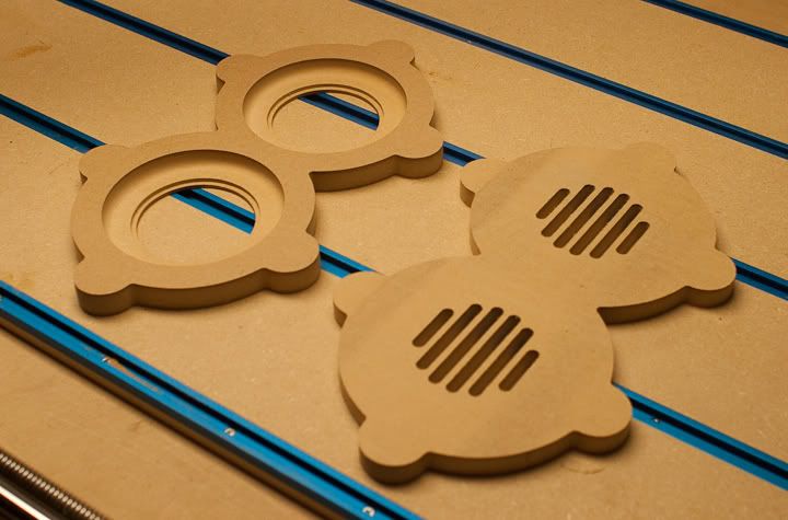
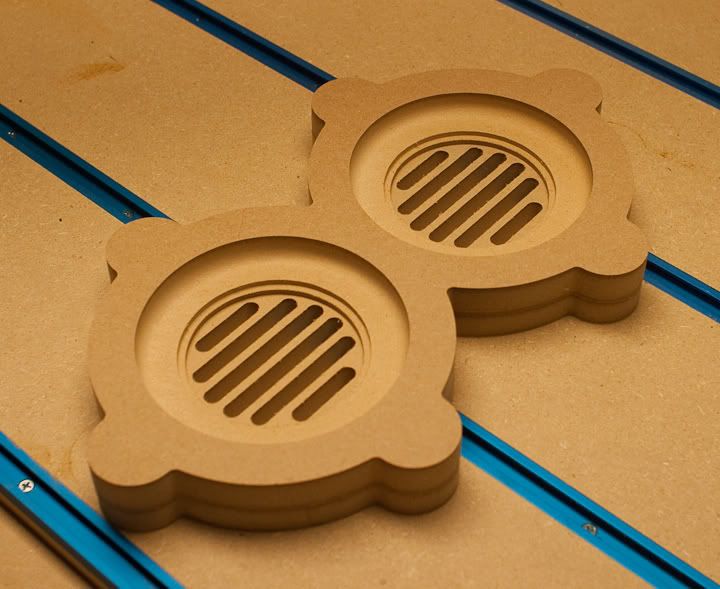
I cut out these two vent frames out of paper thin sheet plastic. After they were cut out and placed into position, they seem like they are still too thick. I wonder If I should just scribe them in instead.Leave a comment:

Leave a comment: