
Right around page 25. THRESHER went down with them installed. Not saying the Permits had them. I believe they were quickly replaced by better technology. There is also some scuttle butt about whether it went down with a 5-blade Skipjack prop or quieter 7-blade prop. I tried to model mine as she might have looked at the time of her loss. I went with the 7-blade prop for several reasons. Document refers to them as 'puffs'. 0859672.pdf
-
Last edited by SubDude; 08-06-2022, 12:35 PM. -
Yeah, I see with PUFFS hydrophones. I am somewhat familiar with PUFFS, but the ones that look like large sharks tooth topside. Good findLast edited by SubICman; 08-06-2022, 12:49 PM.Comment
-
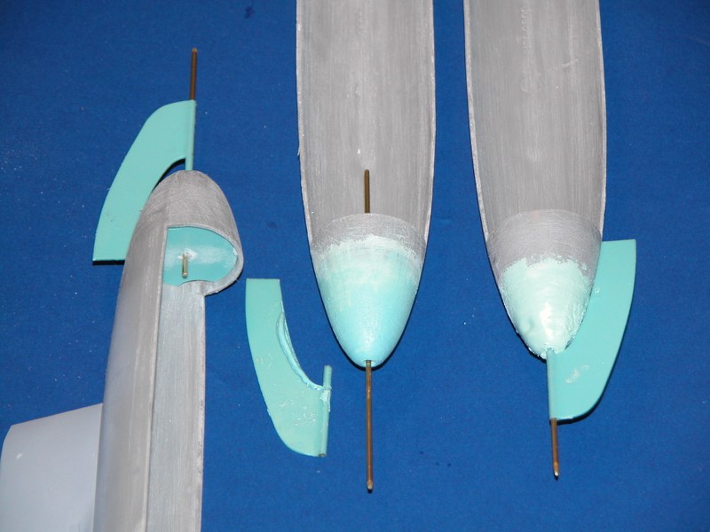
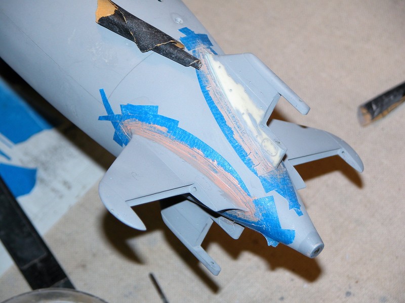
I got the tube (sleeve) today and got it in place. Everything works smoothly as it should. Gudgeons are secured with screws and sanded to shape. Next up will be to secure the tip planes.
Comment
-
Port side is done.
Comment
-
Ok. Tail feathers are done. I now have separate outer tip planes, gudgeons and pintles and inner planes. Next I will work on the control linkages.
Comment
-
You are a frig'n Machine!Who is John Galt?Comment
-
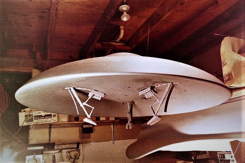
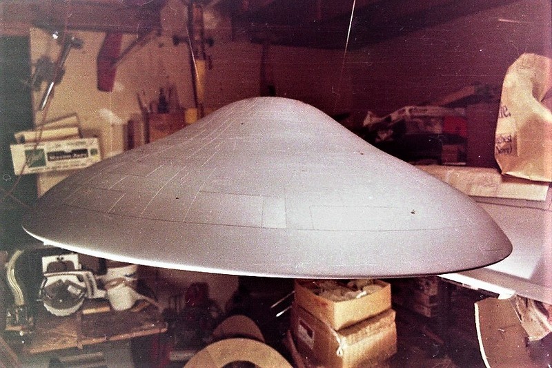
One more top section came off the printer. Just three more to go and the hull parts will be done. Lots of sanding, fitting, filling and sanding to do.
What are the raised areas on the lower hull? As modeled they have very rounded corners. What images I can find they appear to be less rounded.Comment
-
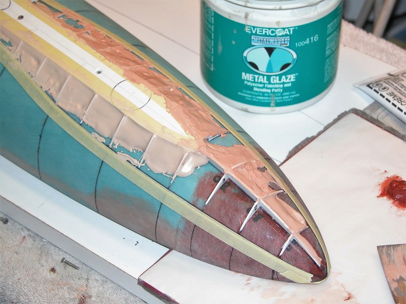
Those six (three on each side) stand-off structures contain arrays of hydrophones that are electronically scanned. They are Wide Aperture Arrays (WAA). Passive sonar that, because of the geometry of their positions on the hull, can derive useful bearing AND range of local noise sources; lets you work up a useful solution without pinging yourself. This is the current offspring of the old PUFFS. Pretty slick. As the exterior structure of all modern American submarines are about 70% pressure hull you can't inlay the WAA hydrophones, that's why the arrays stand proud of the hull. Ugly, but serviceable.
Break out the Bondo and soften the edges between WAA structure and hull. A convex, not concave transition.
David
Task MasterWho is John Galt?Comment
-
David, Steve,
For reference attached are plan and side view projections of the Thresher PUFF's array with dimensions from the Thresher CAD model I made a while back. These were based on photo interpretation / measurement from the Thresher wreck photo's so there is some uncertainty in the actual dimensions, so don't take the 1/4" resolution on the measurements as an indication of accuracy... I need to check my notes again to see if I made some better refinement of the measurements - also I made a post on the forum a few months back with some more details and assessment, I just need to find it again for cross reference (Steve, if I recall correctly this is what you used as reference for your model?).
The Thresher wreck photo's show that the PUFF's arrays were installed on Thresher at the time of her loss. Also there is a drydock photo of USS Barb showing the PUFF's installed, but no other photographic evidence they were installed on other boats of the class.
Comment
-
Here is the link to the thread on the Thresher PUFFS arrays for reference
Comment
-
Yes. Thank you again for the information on the Thresher PUFFS. I could not rember where your thread was but my rendition is based entirely on your find and documentation. I wish there was similar photo evidence for the prop but I know the Navy's stance on that. My gut feel is that it had the 7-blade but I have not been able to determine that for sure.Comment
-
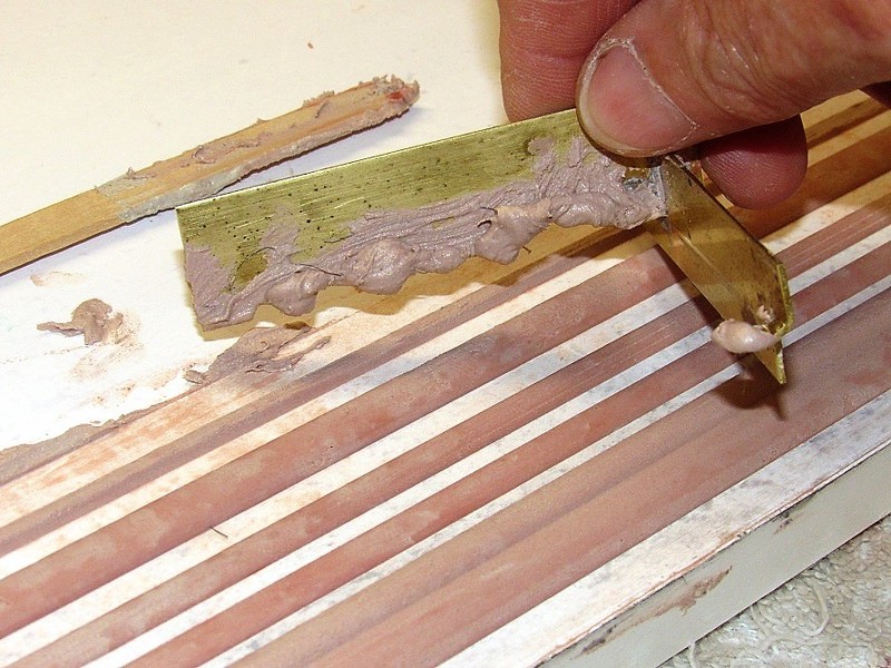
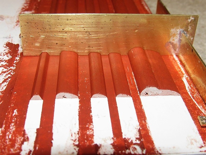
To ensure uniform fillet shape around the perimeter of the WAA 'blisters' make and employ a screeding-blade which you'll use to give form to the still wet Bondo. Makes the filleting go much quicker and with better uniformity than if you winged it with spatula and fingers.
Who is John Galt?Comment


Comment