Okay, i didnt see a picture in your post Steve.
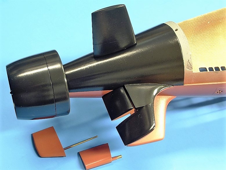
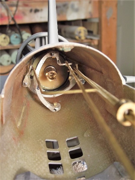
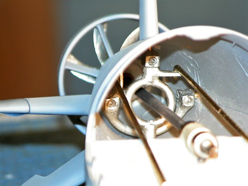
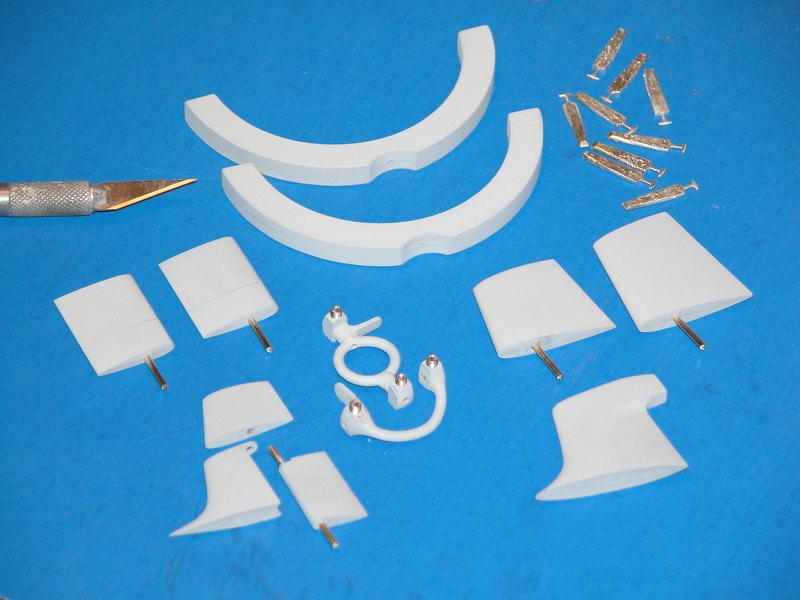
In answer to the previous question of a "tooth". A little further research shows that there is a pintle "tooth" bearing at the end of the stabilizer. I can upload a sketch later.
-
-
-
Steve, whatever you do will be fine. The hull is big enough that it shouldn't be too much of a problem, but if you decide to stay with what you have, it will still work.Leave a comment:
-
-
Well let's see my references. MY EYEBALLS, I saw Seawolf and JC in drydocks while they were still in Groton. Yes that is a Viginia stern and no it isn't the same as a Seawolf. And to cover the other bases, previously qualified COW/DOOW on 88's and previously qualified pilot/copilot on VAs.Leave a comment:
-
-
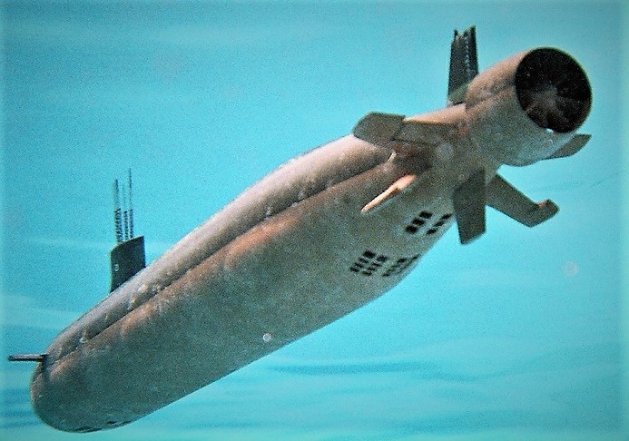
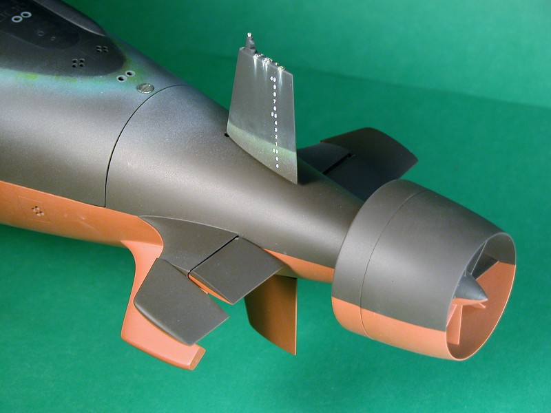
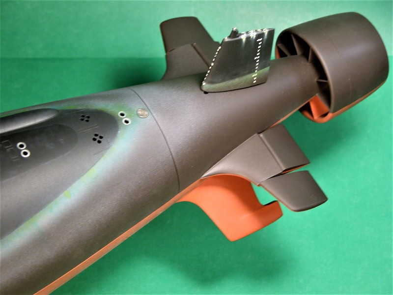
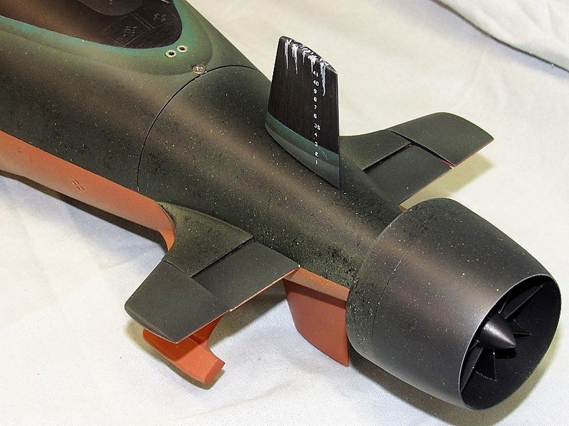
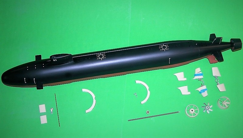
Not sure where people are getting stern shots of the SSN-21 class from, (let's see the reference) but this is the stern of a VA class with a split stern plane config and it looks completely different from what's being discussed. Here's a VA stern shot:
CC
Last edited by CC Clarke; 08-03-2022, 08:12 PM.Leave a comment:
-
-
-
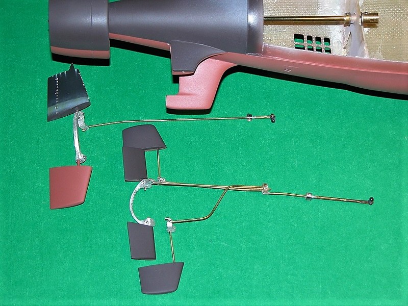
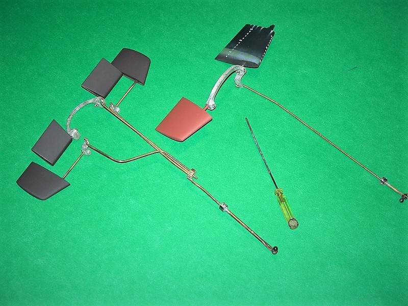
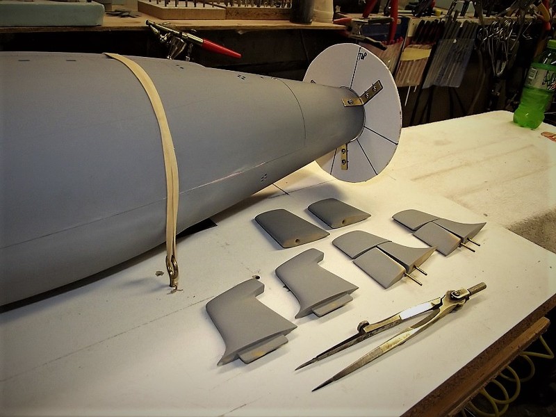
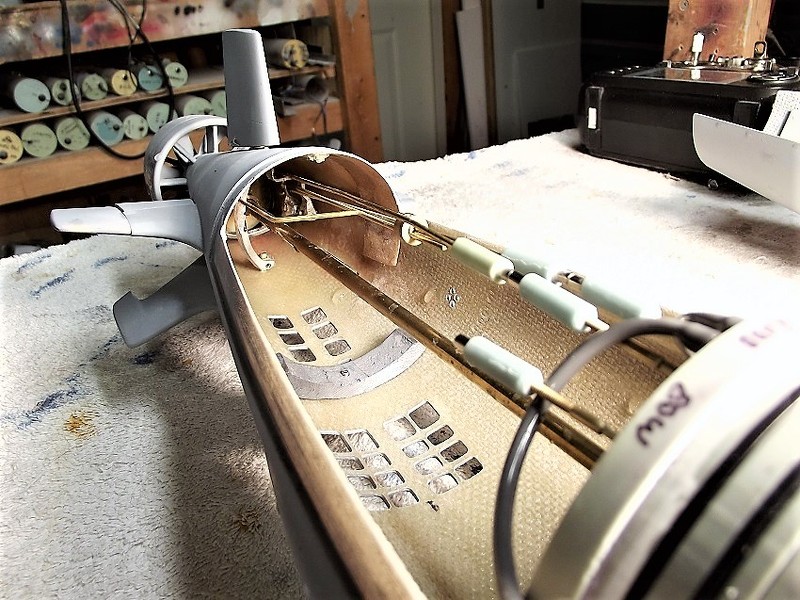
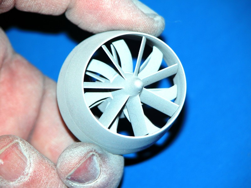
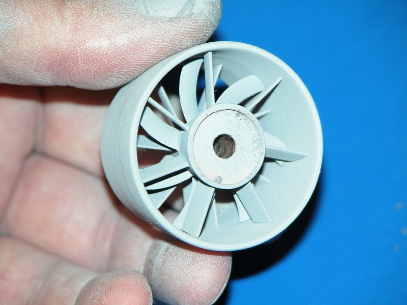
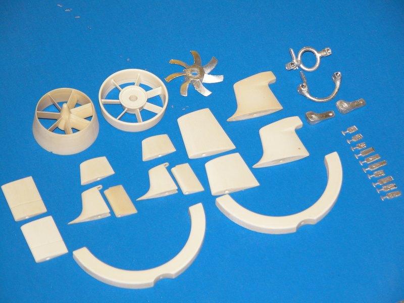
You're spot on, sir. The larger 1/96 model had the room for independently operated stern planes -- one set inboard, the other set the full-flying outboards, each set with their own operating shafts. The smaller 1/144 model only had room for a simplified arrangement which ganged the inboard and outboard control surfaces on a single operating shaft -- a cheat.
DavidLeave a comment:
-
David, did you use a single pivot rod for the surfaces or two? I see what looks like both ways in your pics. The finished model has two but one pic of the raw parts appears to show just one and a support 'tooth' or whatever it's called extending from the fixed horizontal plane?Leave a comment:
Leave a comment: