Thank for the explanation David! I see how it would certainly transfer the heat more evenly to both parts to be joined, especially with smaller slightly beveled tips! Ounce again your craftmanship has come to the forefront!
Rob
"Firemen can stand the heat"
-
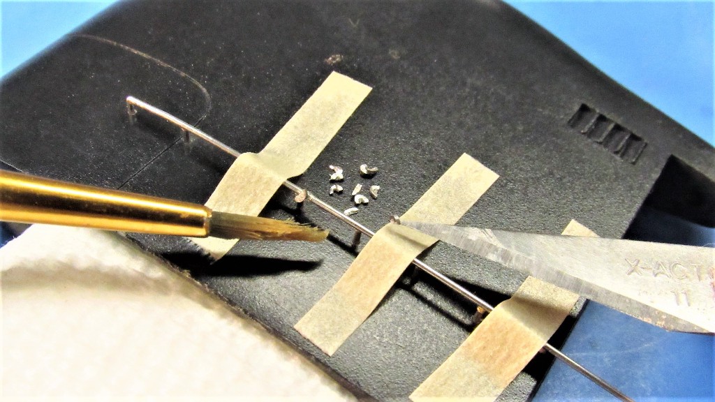
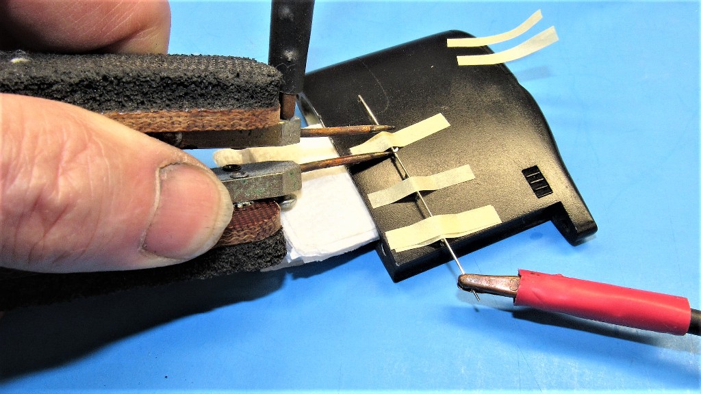
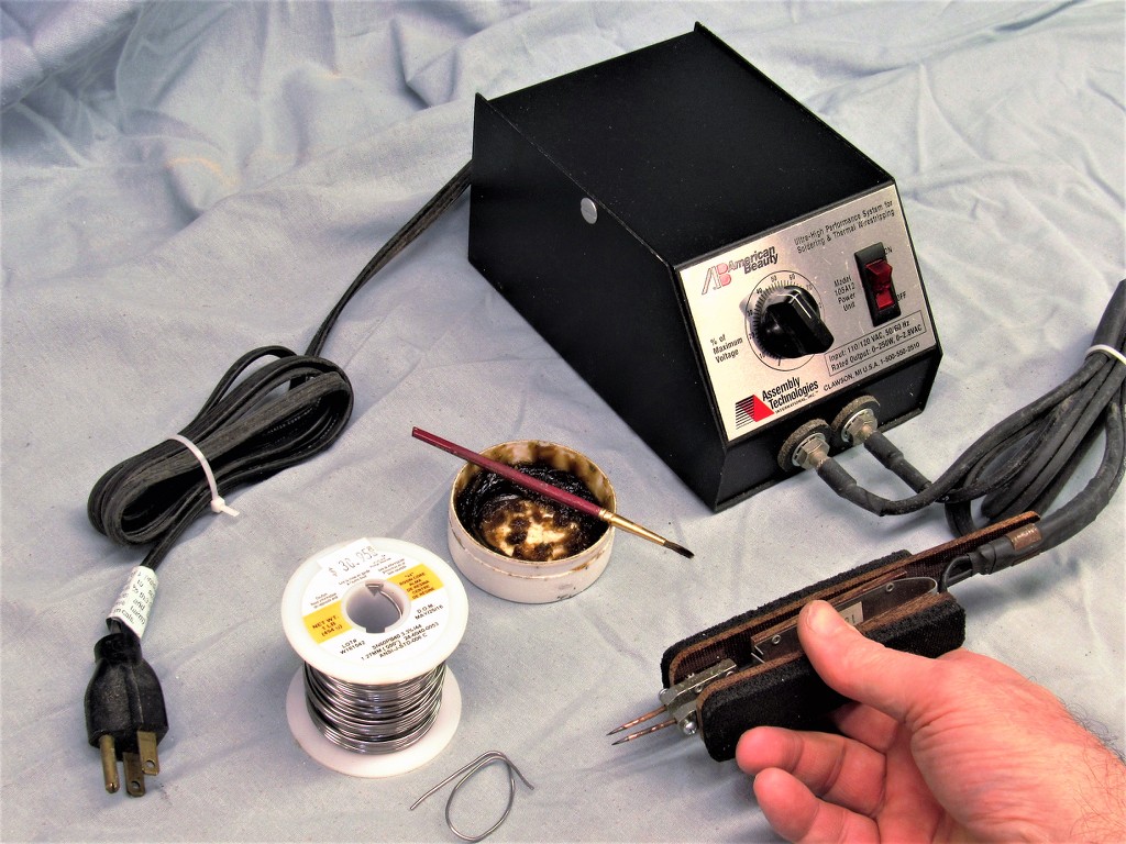
It's just another method of getting the heat to the point of union. Its virtue is that the heat is localized to only the area of slight gap between the two (or more) parts being joined. The mechanism is simple: electrical current bridging a loose connection will encounter resistance, and this results in heat at that union. If the union had been prepared with a coating of flux and a small amount of hard solder that heat will melt the solder and it will instantly bridge the gap between the parts. At the same time the current flow at the union encounters much less resistance and the heat dissipates.
You don't see this machine used much in electronics because the induced current can easily clobber electronic components -- it's devastating to semi-conductors. Dip and iron soldering remain the preferred method when soldering electronic devices.
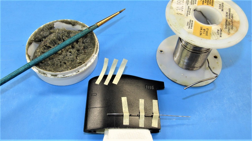
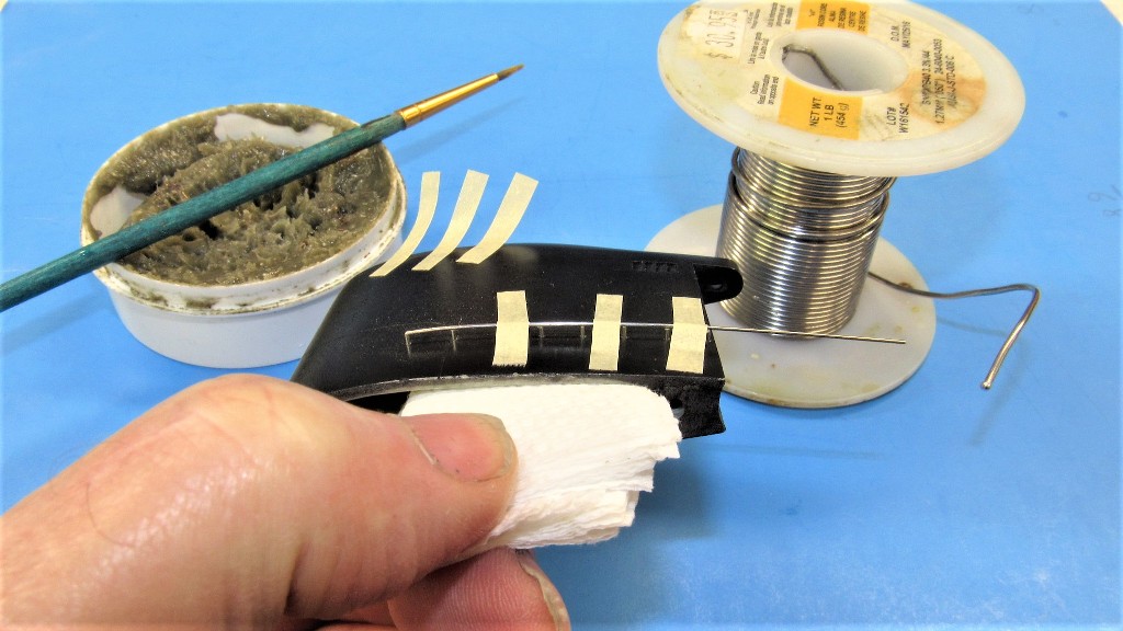
I used the technique on this model as the easily melted resin of the sail was used as the jig that positioned the rail and rail studs as the parts were soldered. An electrode on a stud and an electrode on the rail completed the circuit. A foot kill-switch assured quick and assured control of current.
Other applications of resistive soldering:
:
DavidLast edited by He Who Shall Not Be Named; 01-06-2021, 07:32 AM.Leave a comment:
-
David,
I have done tons of soldering when I was building shortwave radios! I have never heard of Resistive Soldering or that such a machine even existed! This is old tech knowledge i am assuming!? Is it specific to certain metals?
Nice work on that railing.
Rob
"Firemen can stand the heat"Leave a comment:
-
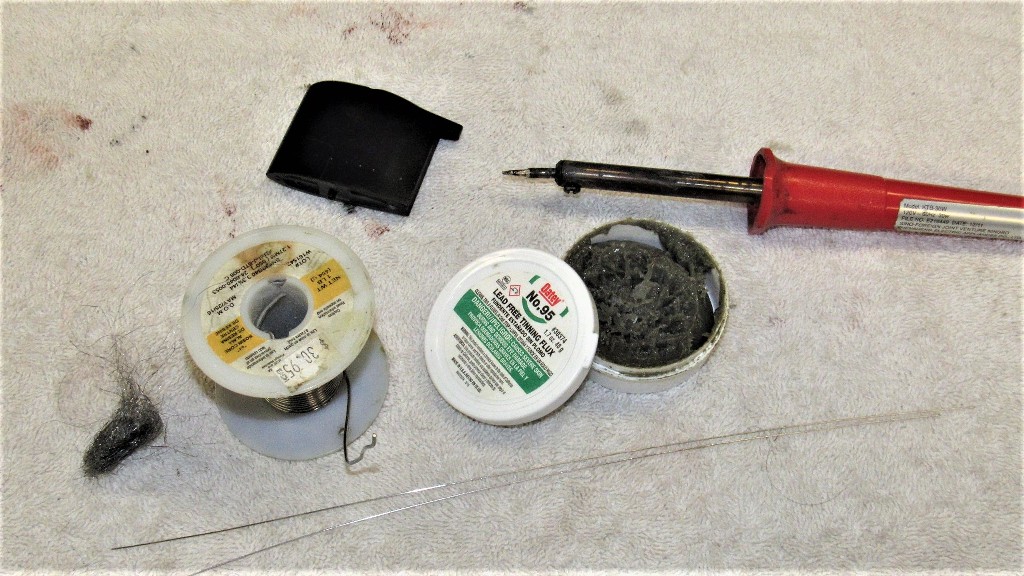
I used the resistive soldering machine to adhere the sail railing parts together.

Leave a comment:
-
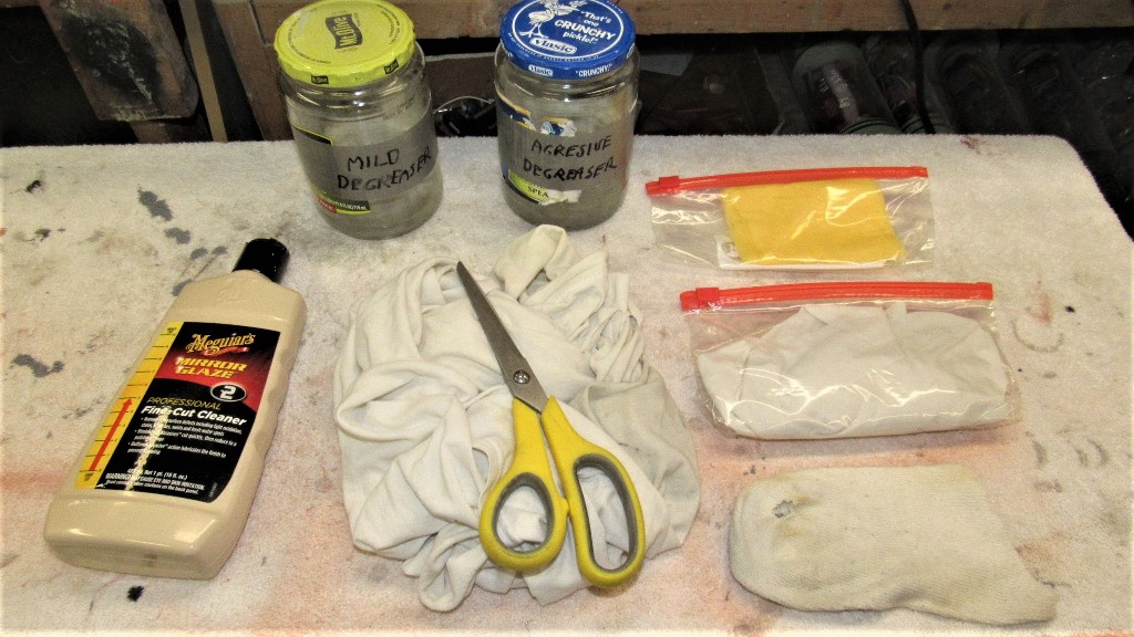
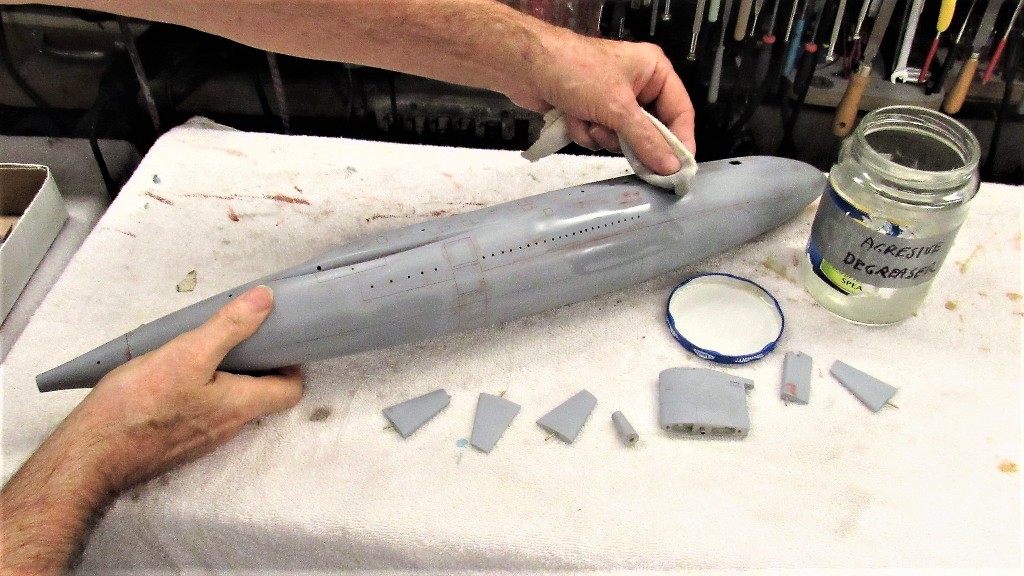
I prepare a models surface for painting by a careful wet-sanding with #600 grit sandpaper. After drying the model parts, all surfaces are wiped with a tack-rag to remove any dust. And, finally, a de-greaser is wiped over the parts and they are left to dry. Only then does the first coat of paint go down.
(Hope Ellie does not read this post, as it would solve the, 'where do your T-shirts go?' mystery)
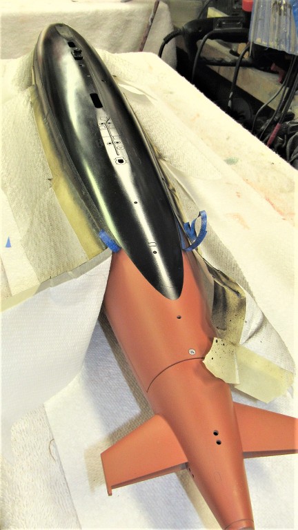
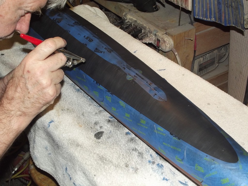
Time had come to paint the 1/96 ALBACORE black.

The preferred paint chemistry for my r/c submarine models is the two-part, polyurethane ChromaColor brand produced by DuPont -- no longer available... thank you, California!!! This is a great coating system: tough, UV tolerant, dries quickly, and the pigments are extremely opaque. I love the stuff!
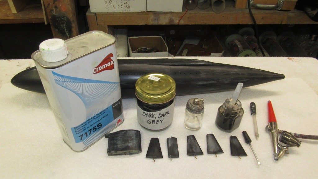
But this stuff will tear up your lungs if a charcoal or forced air mask is not used. A word to the wise.
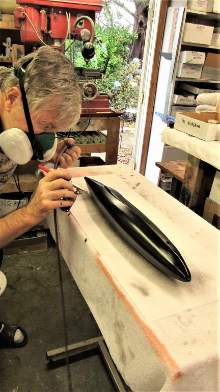
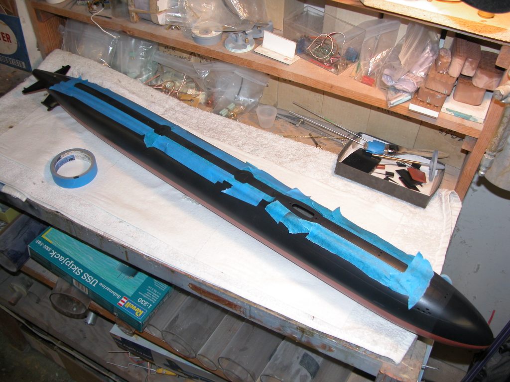
Once you mix the paint with its catalyst you have to use it within a days time or the paint will cure in the bottle. So, for economies sake (I can no longer buy this stuff... than you California!!!!) I plan my work so that more than one model will receive the color mixed. Such is the case here: I also laid down the black on a 1/96 SKIPJACK model I'm getting ready for the 2021 model boating season.
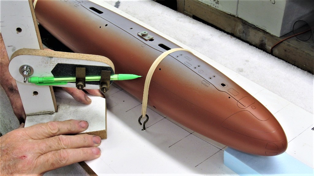
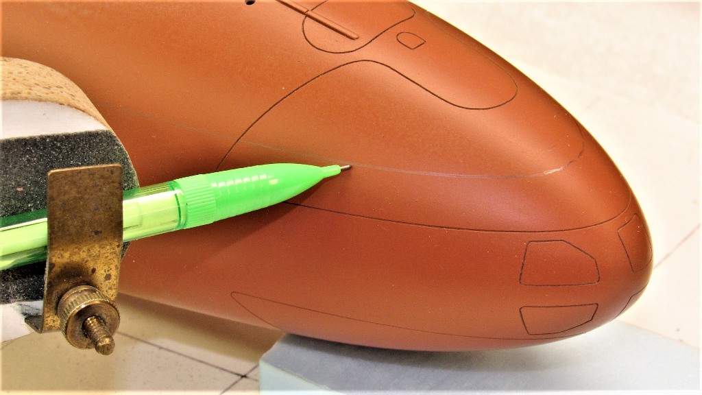
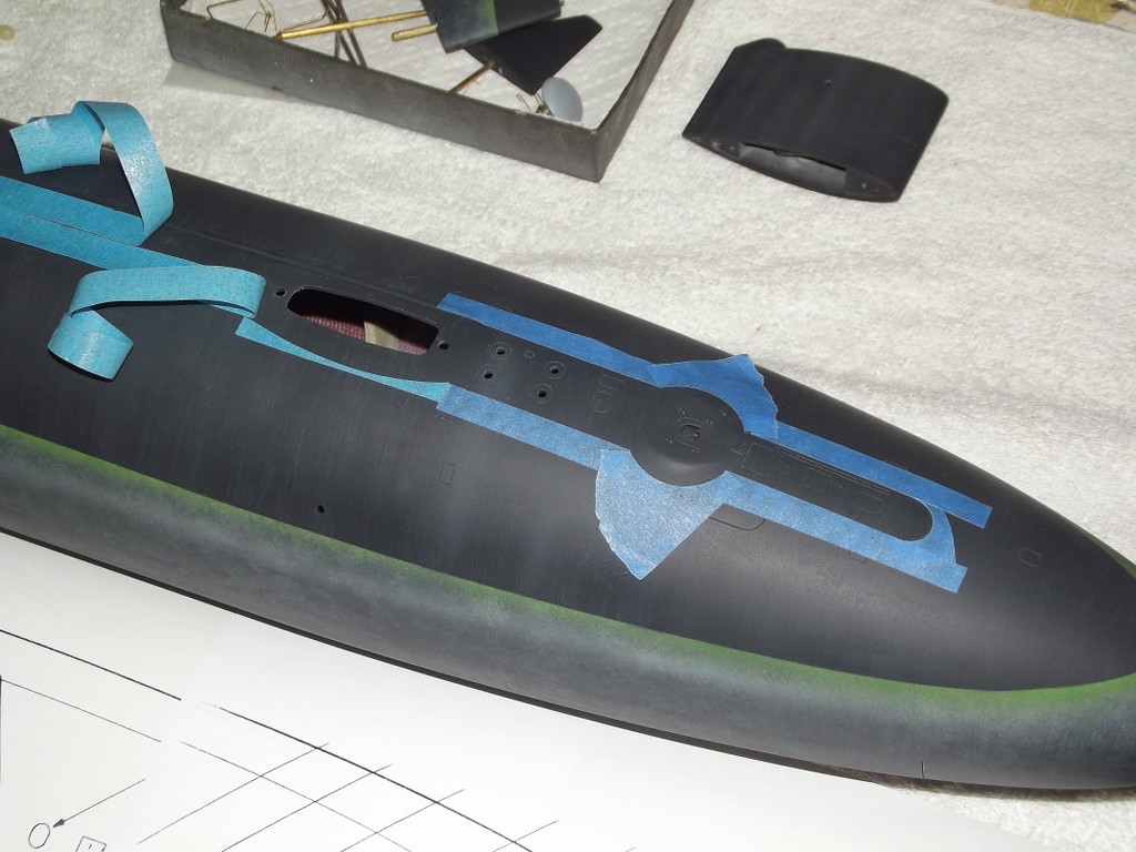
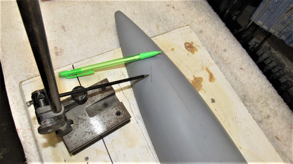
As this model had the red-black demarcation line at the boats designed waterline in surface trim, I had to first mount the model on a flat board, pitched up so that the waterline could be marked off with pencil with the aid of a 'waterline marking tool' (a pencil loaded Machinist's surface gauge, if you will).

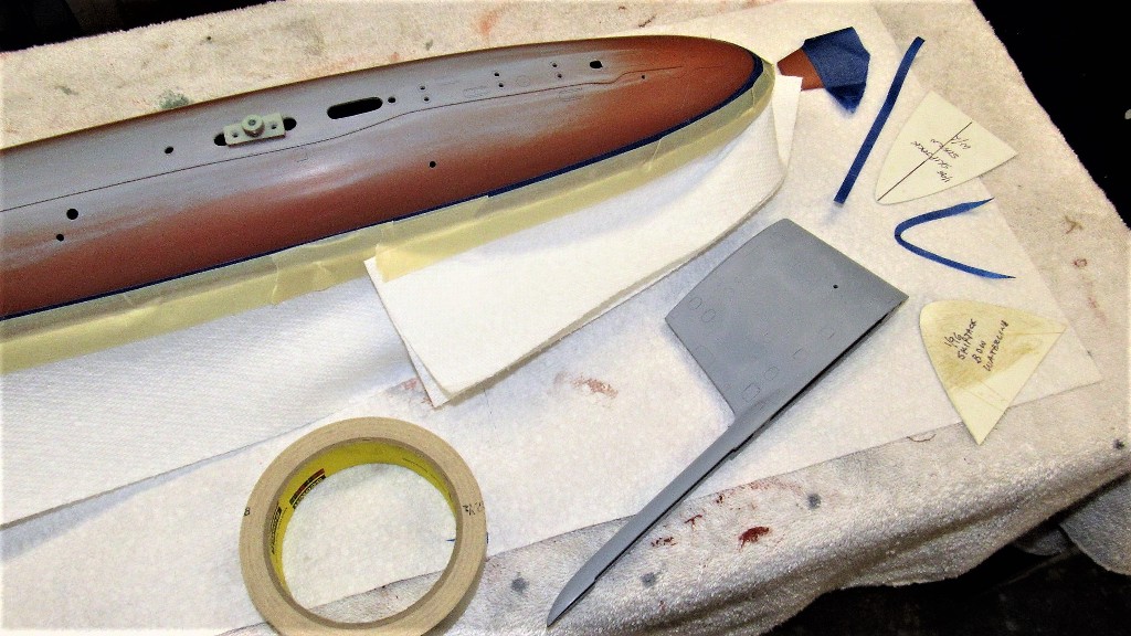
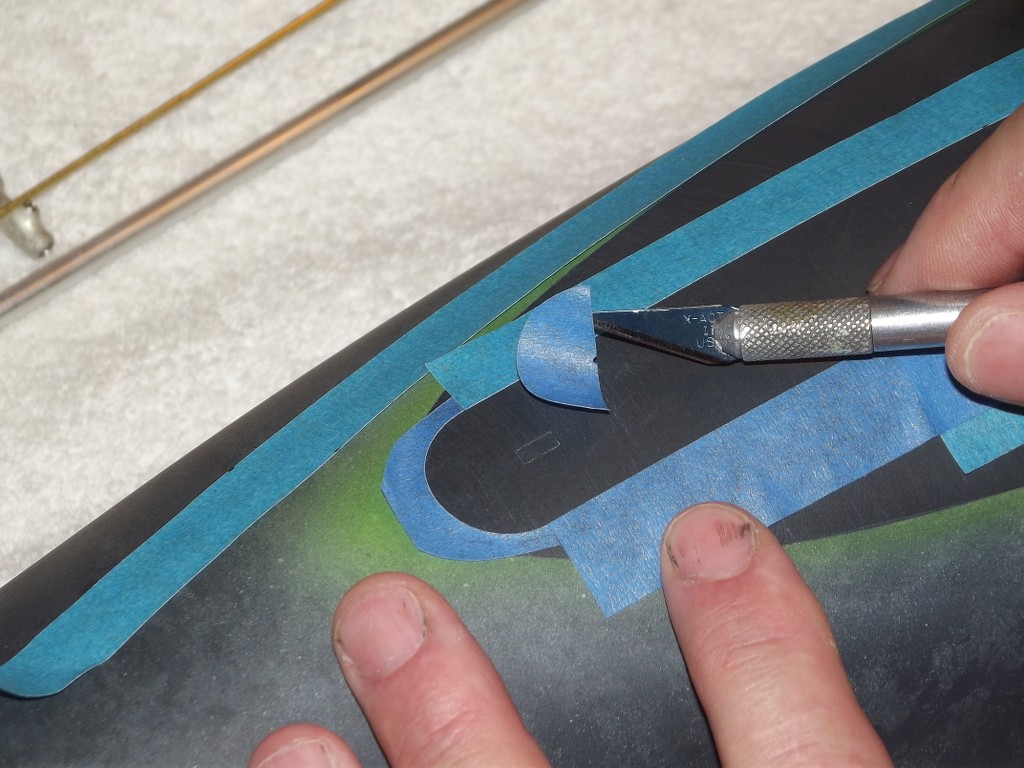
As this 1/96 SKIPJACK was far from my first, I broke out the old masking templates and used them to cut out masks for the pronounced curves at the bow and near the stern. These masks, and long straight strips were laid down on the model using the penciled cheat-lines as a guide. Paper towels were added to keep paint overspray from getting on the anti-foul red portions of the model.


Leave a comment:
-
Must remember how you dealt with those "hard-to-get-at area"....learned something new again.
Great work David.
Grtz,
Bart
Leave a comment:
-
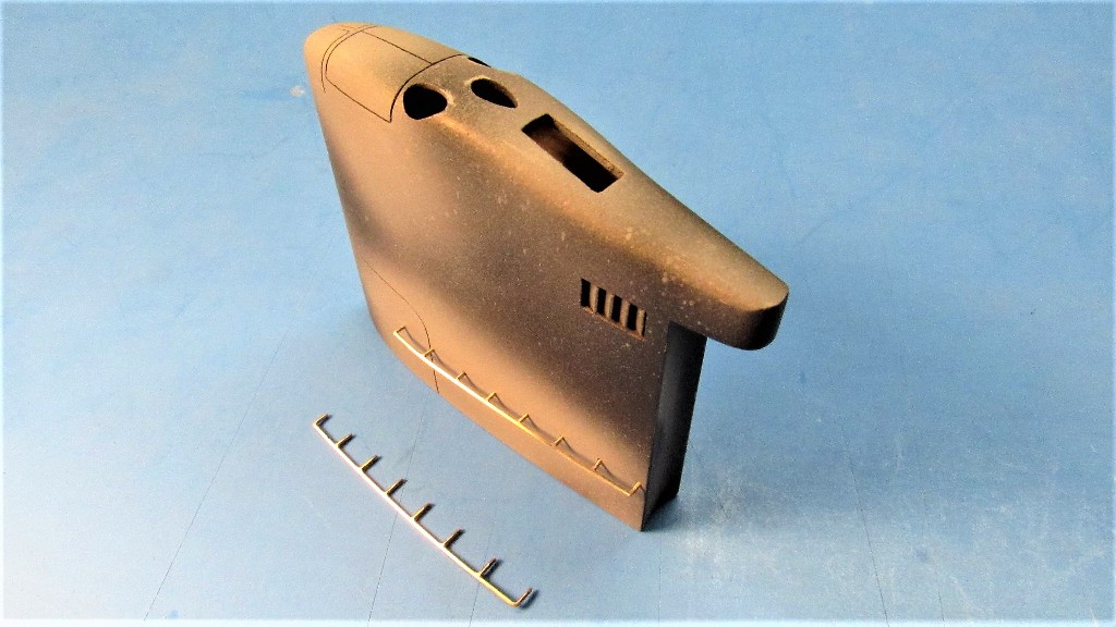
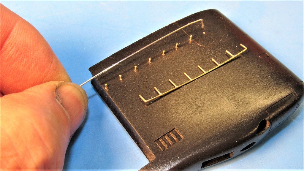
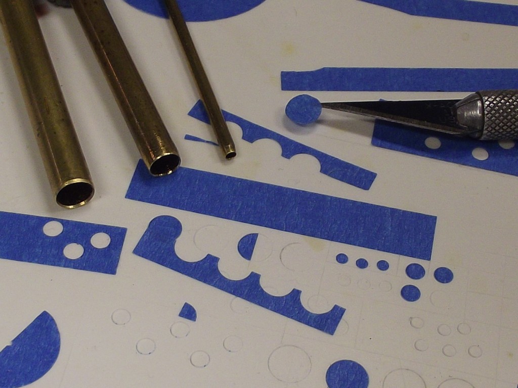
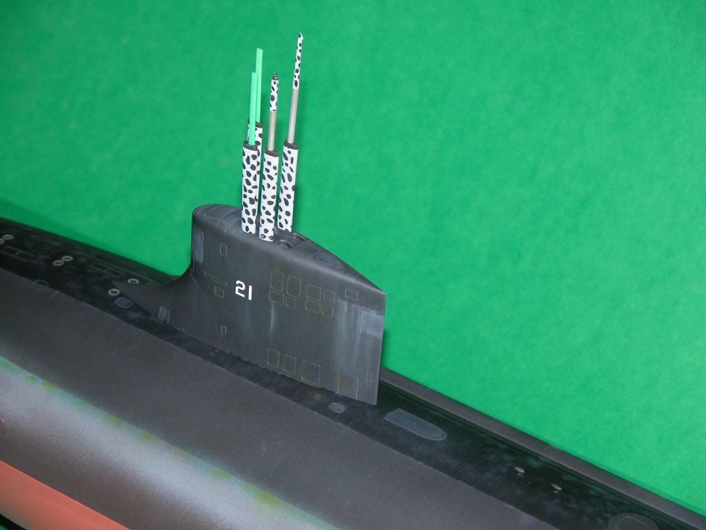
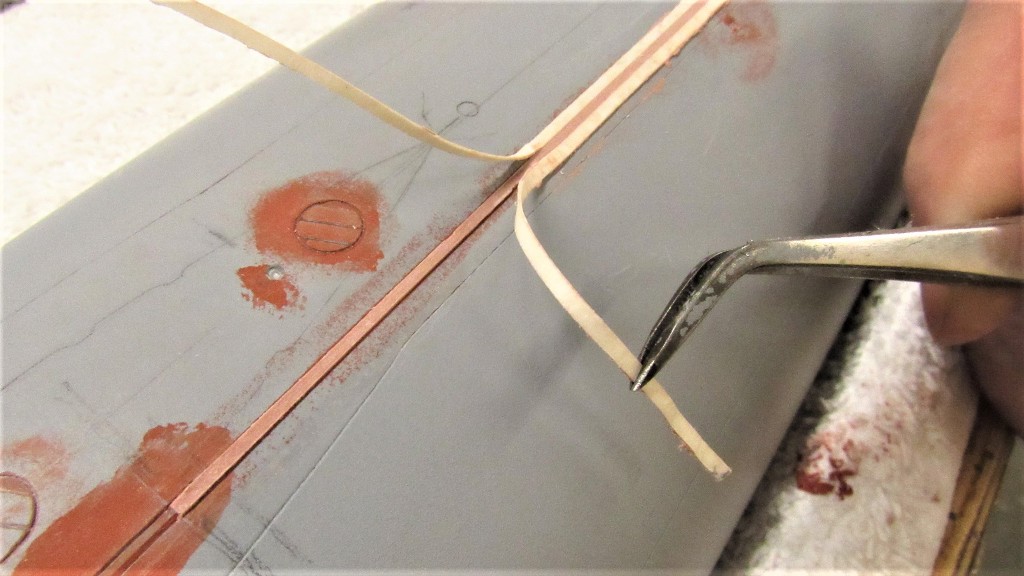
Time had come to represent the sections of safety-track that run atop the hull, near deck level. In actuality these are T-section tracks, The bottom of the 'T' welded to the deck and the top of the 'T' becoming the race that accepts horse-shoe shaped runners that attach by lanyard to a sailor's safety harness. The idea is that once you shackle into the track you are free to run up and down the length of deck. Bull-****! You almost always became a dog-snapped-to-a-halt-by-his-leash as the runner snagged the track. I wonder if they ever came up with something better?
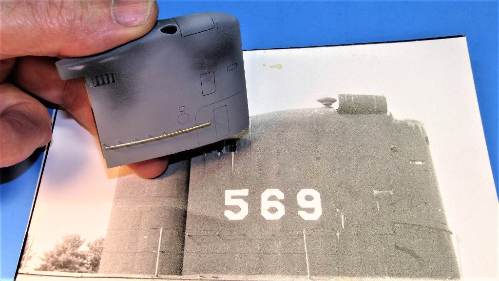
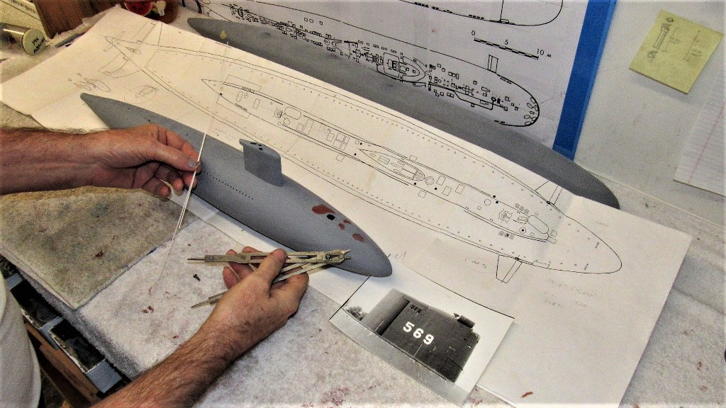
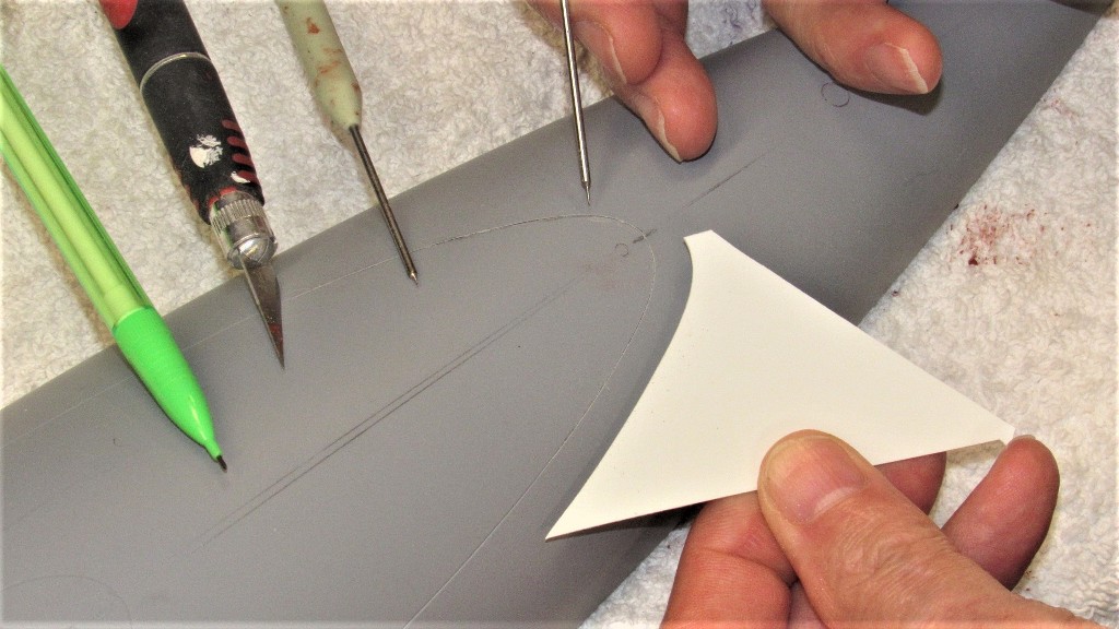
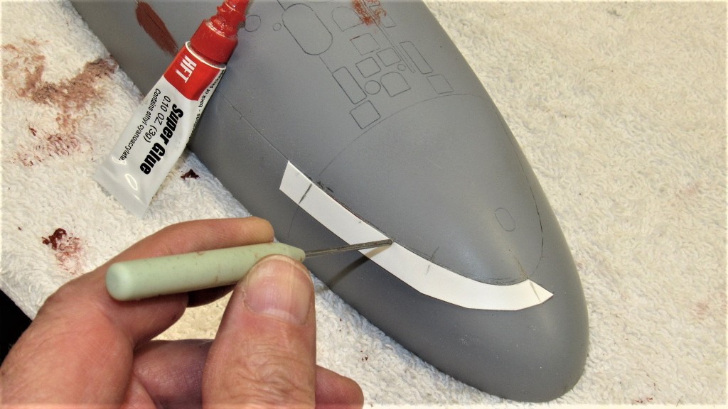
On the model I represented each section of track -- broken at points to clear line-locker hatches and such -- by a length of round styrene rod. As the real track was about three-inches in width, that comes out to a model width of about .031" at 1/96 scale. I dug a shallow trench where each of the five lengths of safety track would go and CA'ed each safety track in place. The work went surprisingly fast, an evenings work.
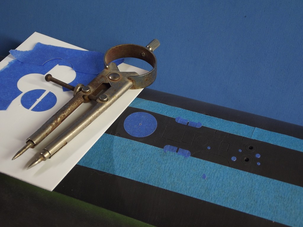
The only authoritative drawing I had representing safety-track placement was a plan I prepared for Skip Asay's 1/60 ALBACORE kit some twenty years ago. As that document was in 1/60th scale I was compelled to use my proportional dividers to mechanically transpose from that scale to the one I'm currently working, 1/96. The model so marked I dug out the trenches that would receive each length of round styrene.
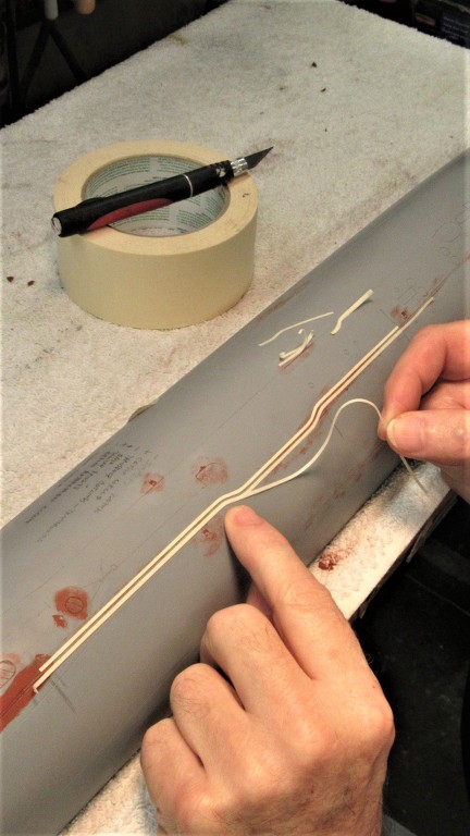
Each length of rod was tack-glued in place with small drops of CA placed in the trench. Each trench stared as a deep knife slit in the deck done with the aid of a steel straight-edge. The depth of the cut increased with the aid of a razor-saw. I then used a modified rat-tail file, ground to shape to become a push-chisel, to give shape to the semi-circular trench.
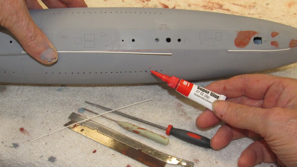
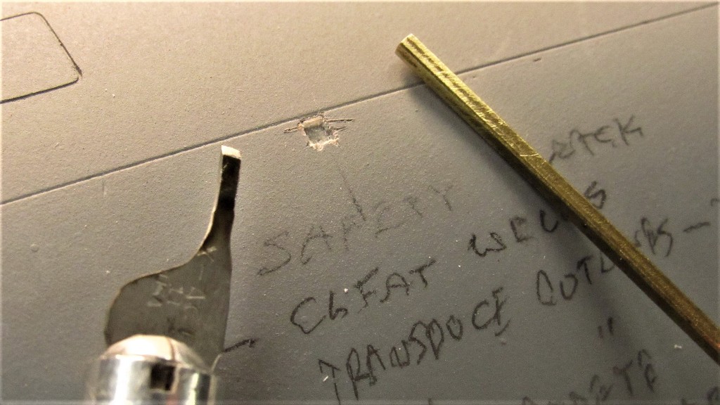
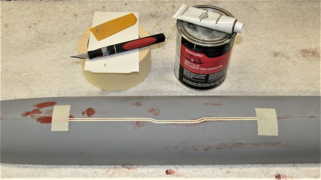
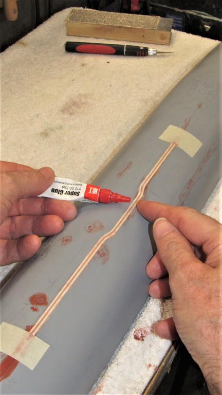
I then applied a continuous bead of CA with the aid of an 'application knife' -- this tool worked to place the adhesive at the base of the rod from which it would wick down into the trench, insuring a strong bond with the minimum amount of glue requiring later clean up with file and sandpaper.

The CA was quickly zapped to a hard state with a liberal dosing of accelerator.
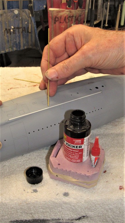
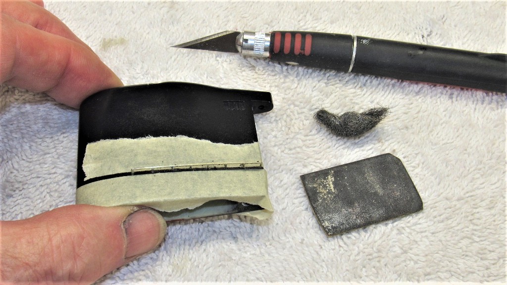
The 'flat' of the safety-track was achieved by simply sanding the rod flat at its top.

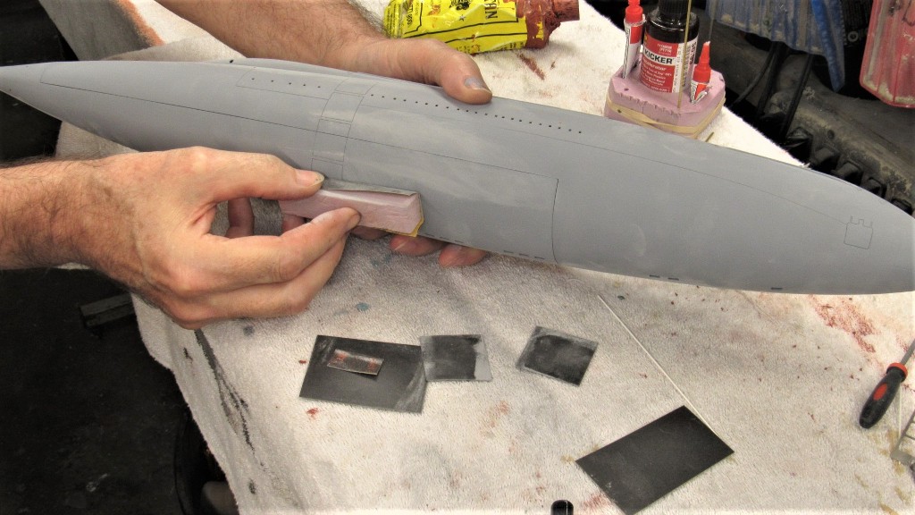
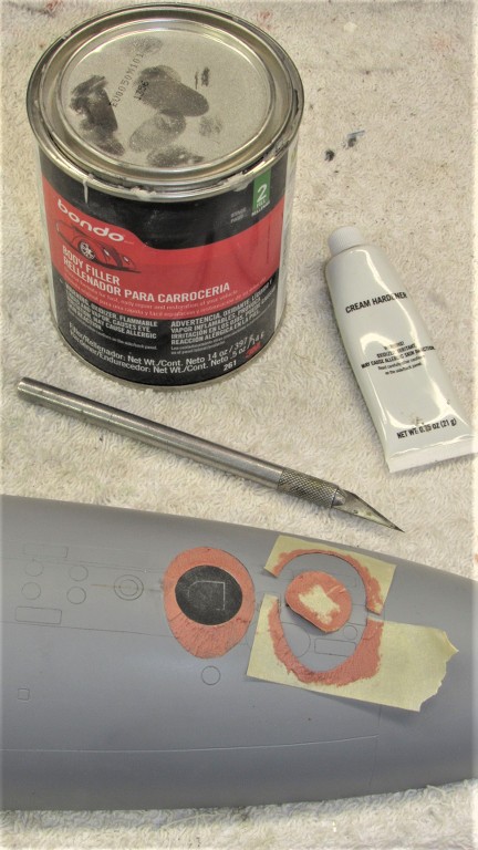
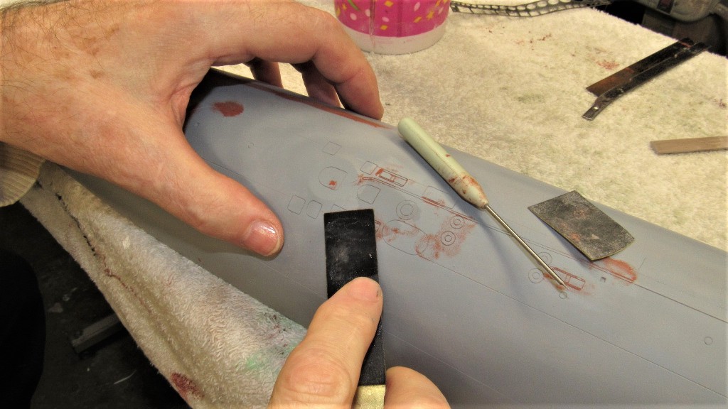
Some touch-up putty work and the model was sanded, touch-up primed, sanded again, and readied for painting by a good scrubbing with de-greaser.
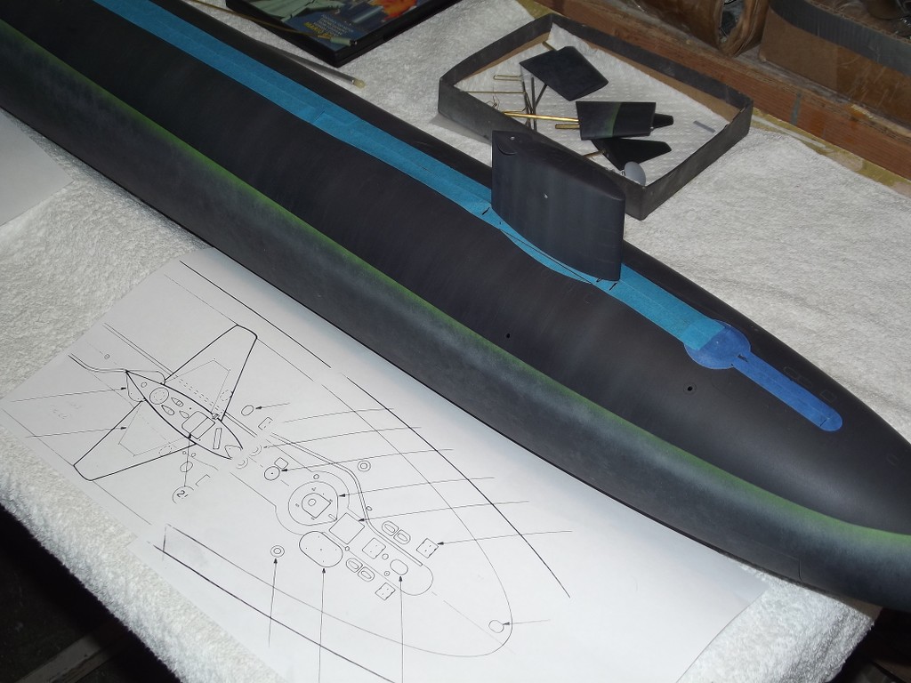
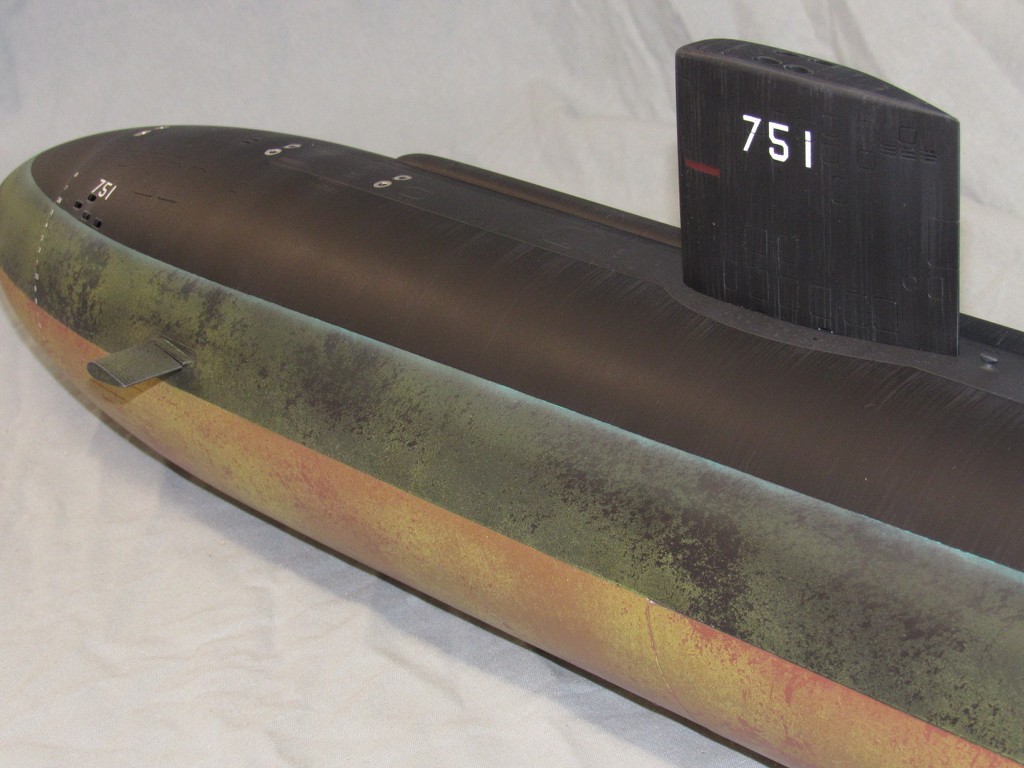
A dark, dark gray paint was mixed and spot applied to all edges, holes, and hard-to-get-at areas of the model.
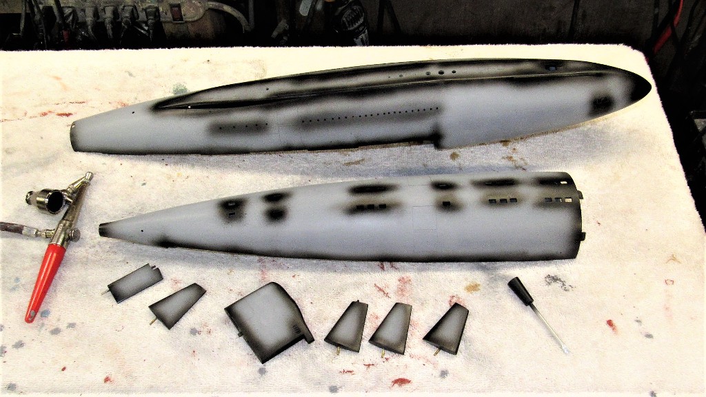

I then blasted the entire model with the dark, dark gray.Leave a comment:
-
Hey, Tom.
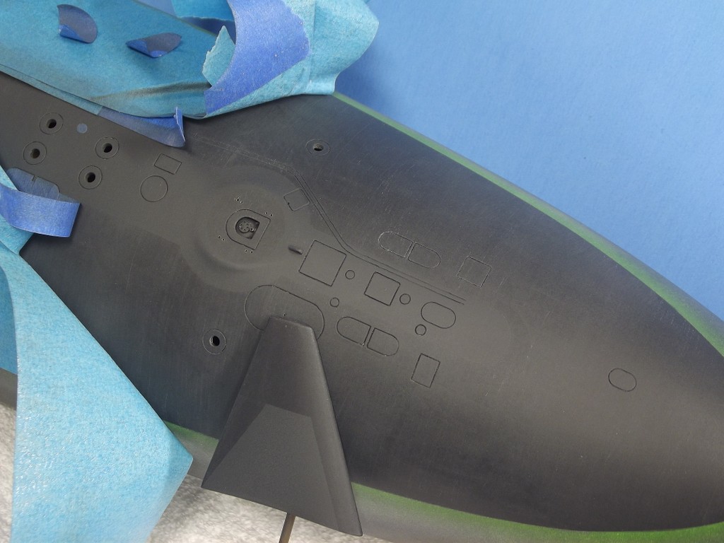
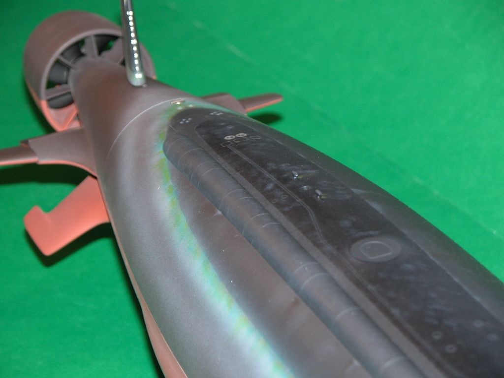
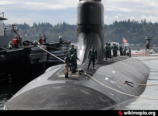
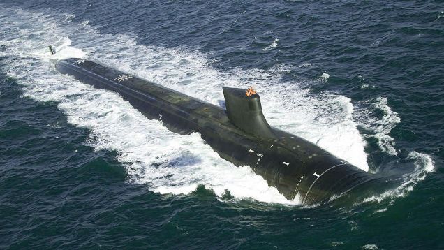
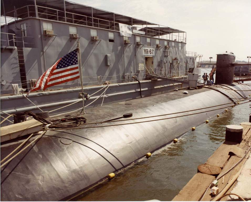
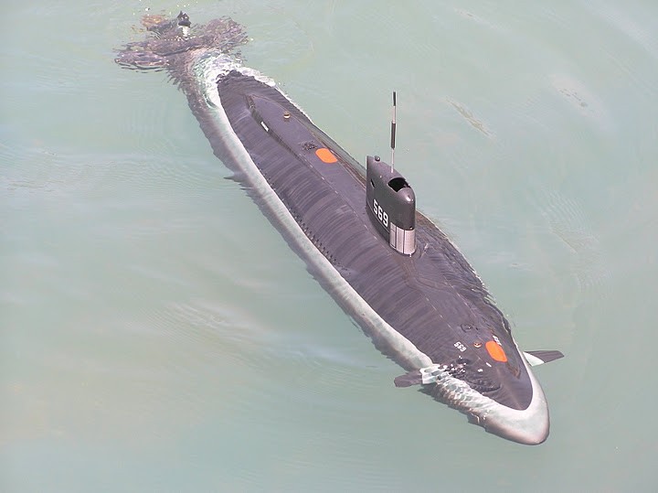
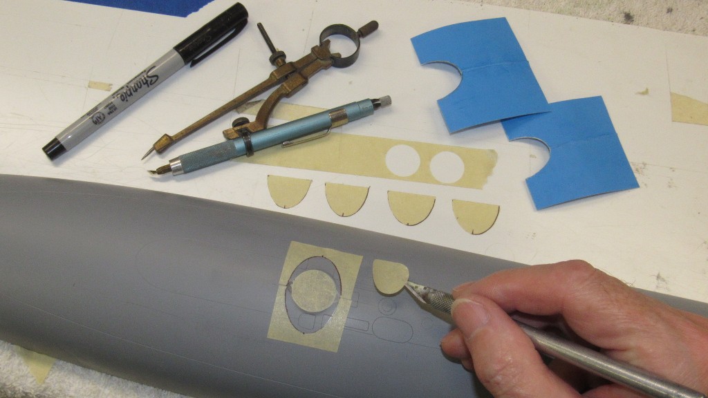
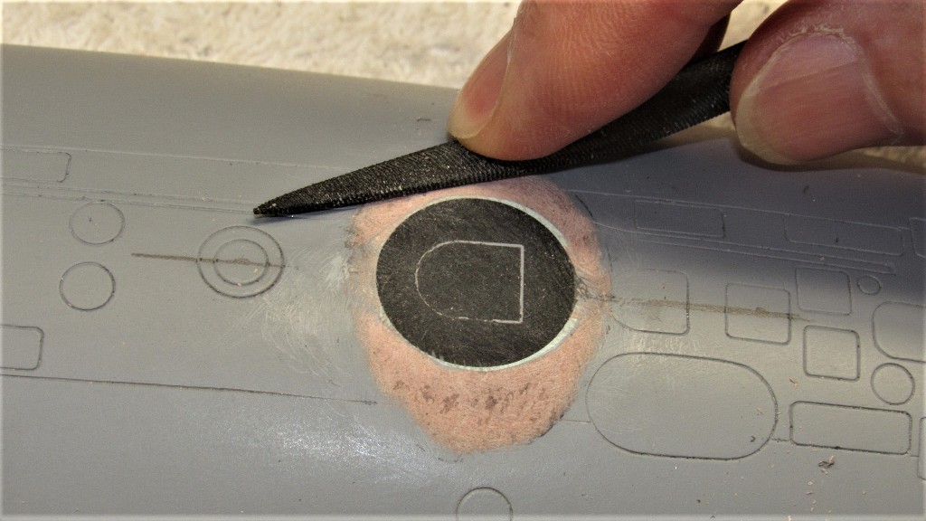
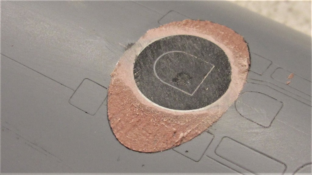
The circular area around the escape hatches (where the McCain rescue chamber or DSRV would seat) had to be non-skid free. The rest of the deck was coated with 'flight-deck non-skid'. A very abrasive material that assured good footing no matter what. On models I represent it by a slightly whitened shade of the dark dark gray or black.
Example of this non-skid on some of my models and a few shots of prototypes in the mix as well.


Leave a comment:
-
David, the hatch detail, are you using sandpaper to represent no-slip texture?Leave a comment:
-
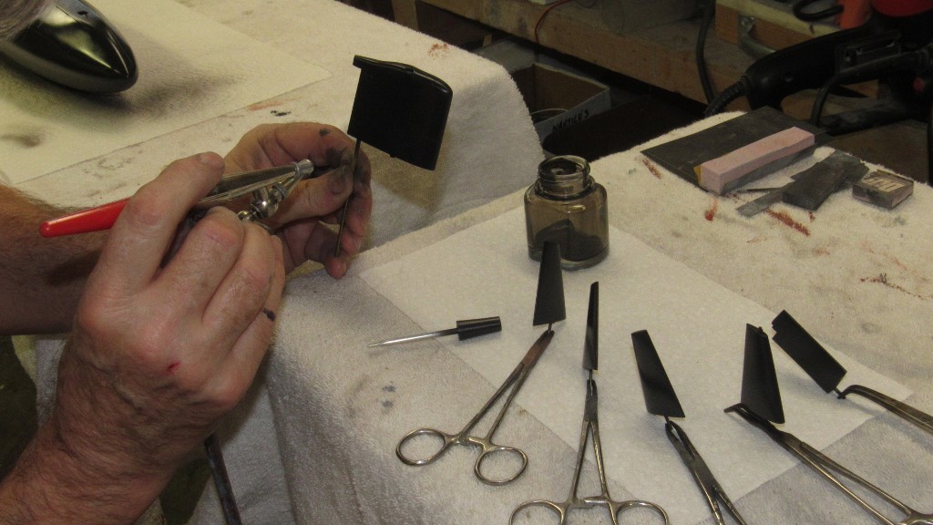
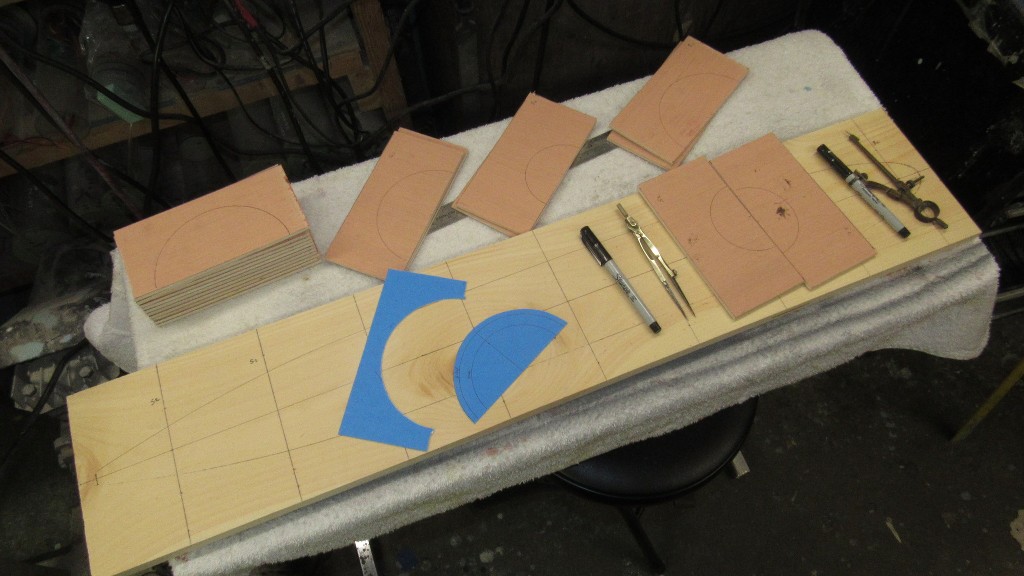
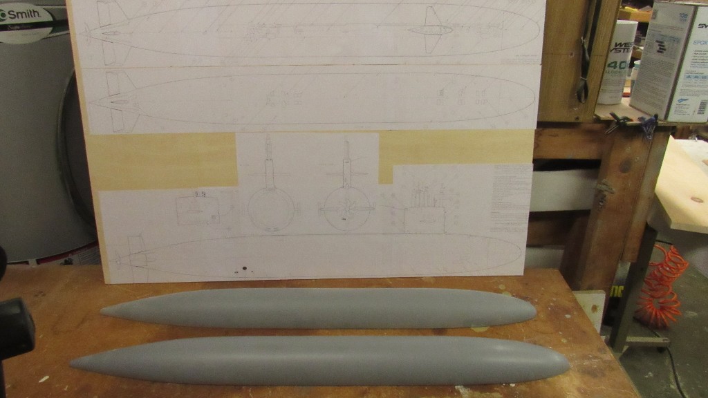
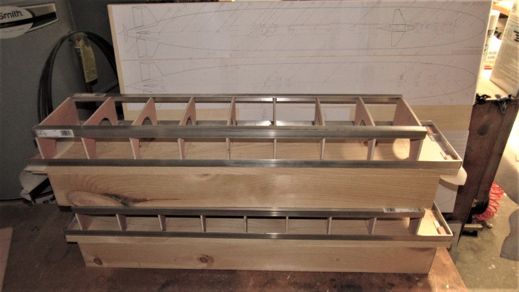
I'll spend the rest of today installing the safety-tracks, then I have to put it up for awhile. I'm detailing the masters of the Thor 1/96 STURGEON's Bob entrusted to me to get proper production tooling done. That and some work for a one-handed friend, and then I'm back on your little beast.
Here are some shots of that work:


DavidLeave a comment:
-
I'm so glad that you have the time to have some fun now; and what a great job you're doing on that little rocket ship.Leave a comment:
-
OK. I'm officially retarded... er.... retired! Now, back to work on Scott Terrey's beautiful little ALBACORE kit.
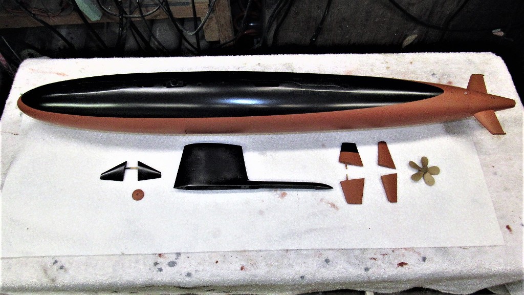
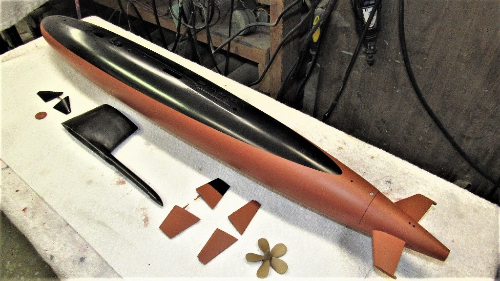
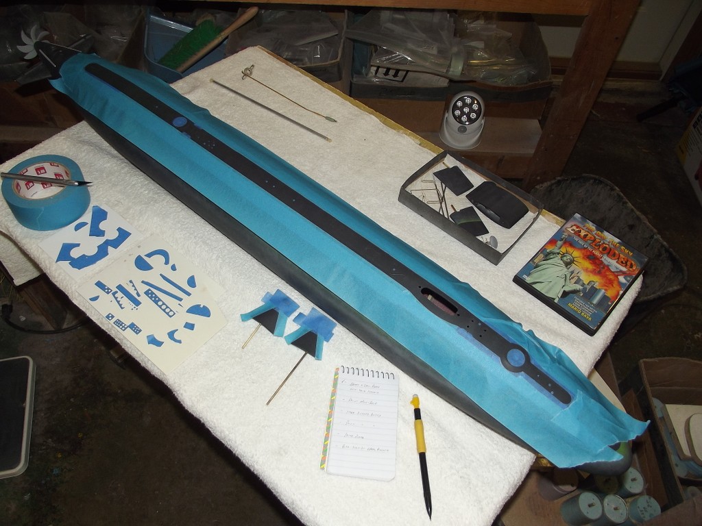
Here's a recap on work done in the last week. Almost ready for paint, only remaining task is to place external safety tracks atop the deck and fabricate railing for the sides of the sail. I'll attend to the safety tracks after I post this and will get onto the hand-railing tomorrow.
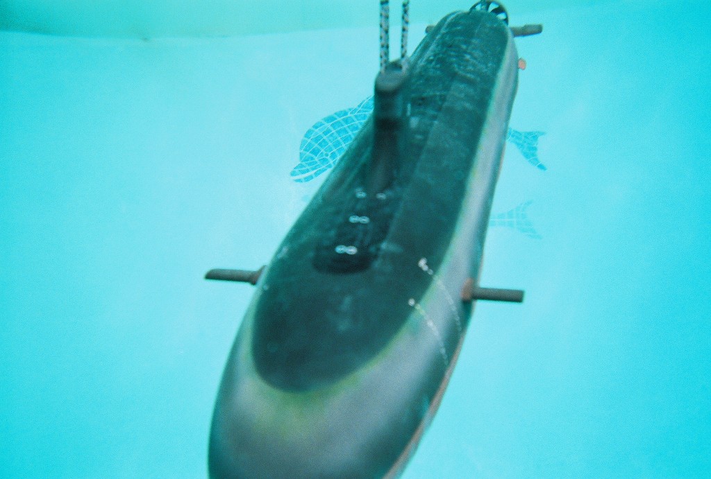
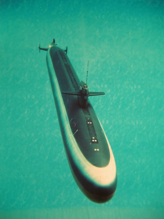
I had already gotten this model to the stage of operating it in the water, but still in primer gray. Here's a video of the initial in-water test of this little speed demon: https://youtu.be/4NIRblzfz_8
Returning home after that preliminary run I took it all down to parade-rest and placed everything in storage so I could go back to production work. Here's a look at all the devices, SD, and nick-knacks that go into making this model submarine work and look like a phase-4 ALBACORE. It all works... even the dorsal rudder works, it is slaved to its own angle-keeper -- oriented to detect and send corrective signals to the dorsal rudder servo to effect correction of motion about the roll axis. Pretty slick!
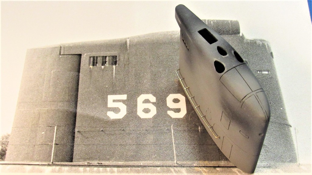
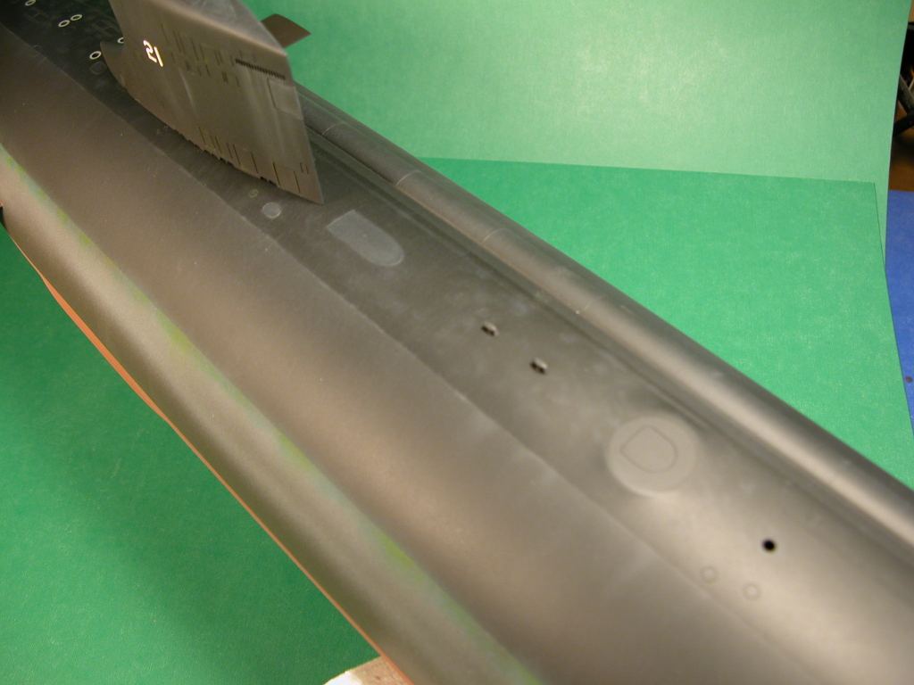
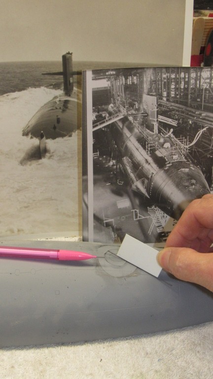
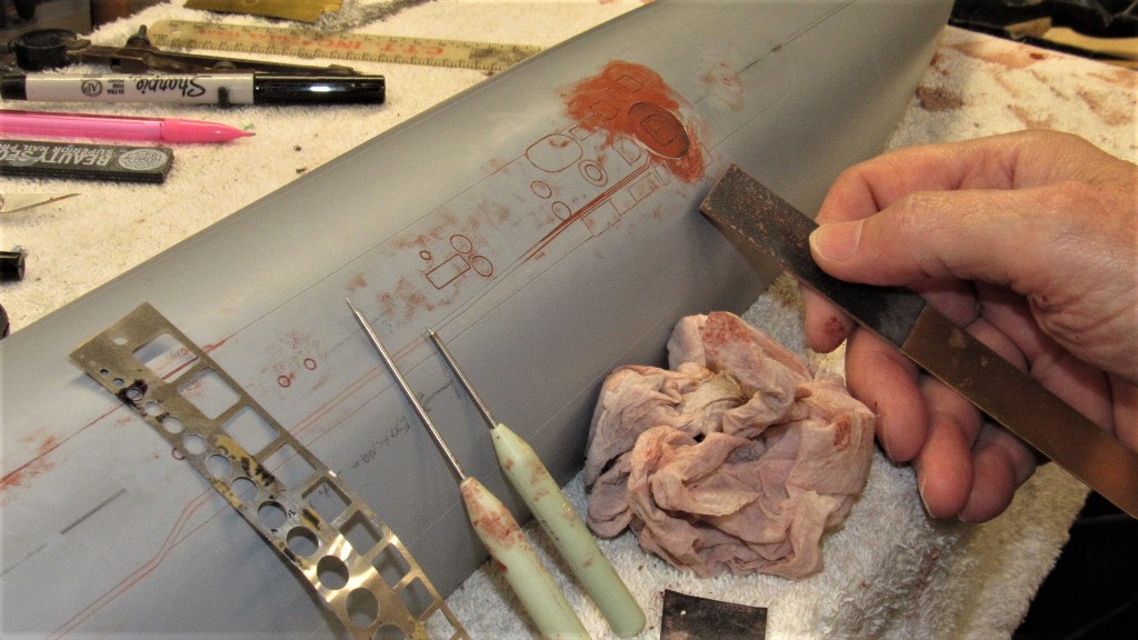
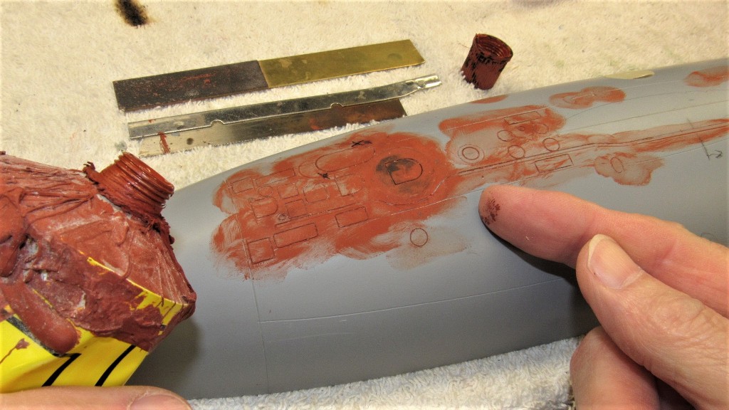
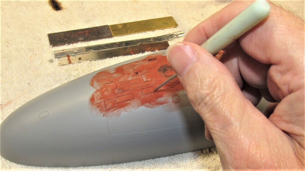
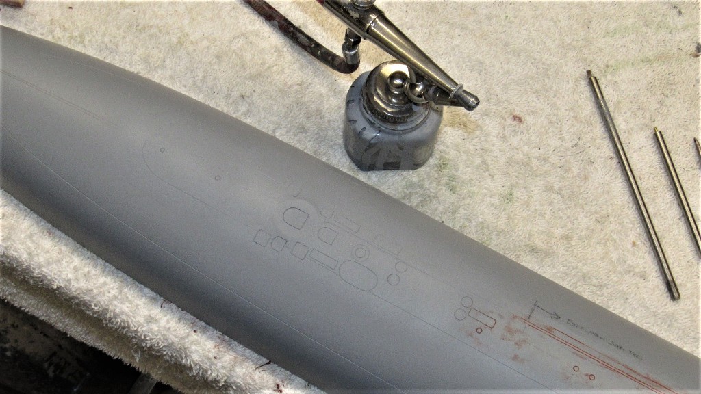
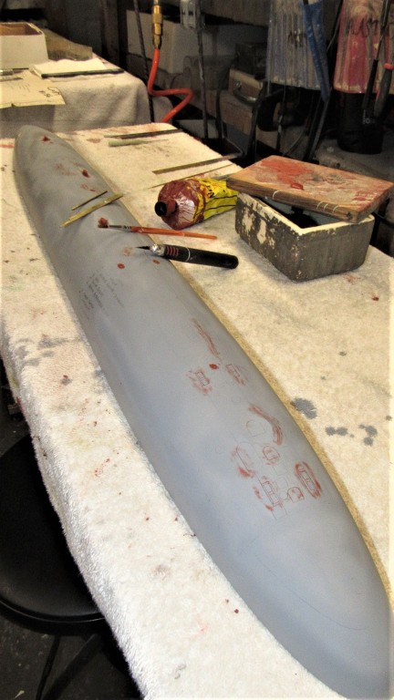
So, after I pulled the 1/96 ALBACORE hull down off the wall I dusted it off and started in on refining the existing engraving as well as adding more engraved lines I was able to identify from my research pile. Fortunately Scott's gel-coat was most receptive to the engraving process.
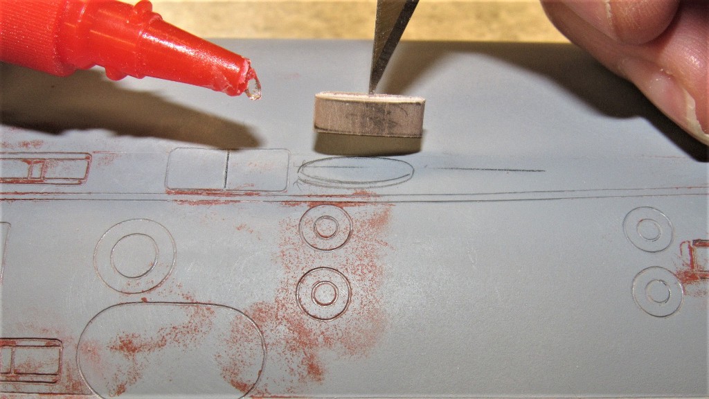
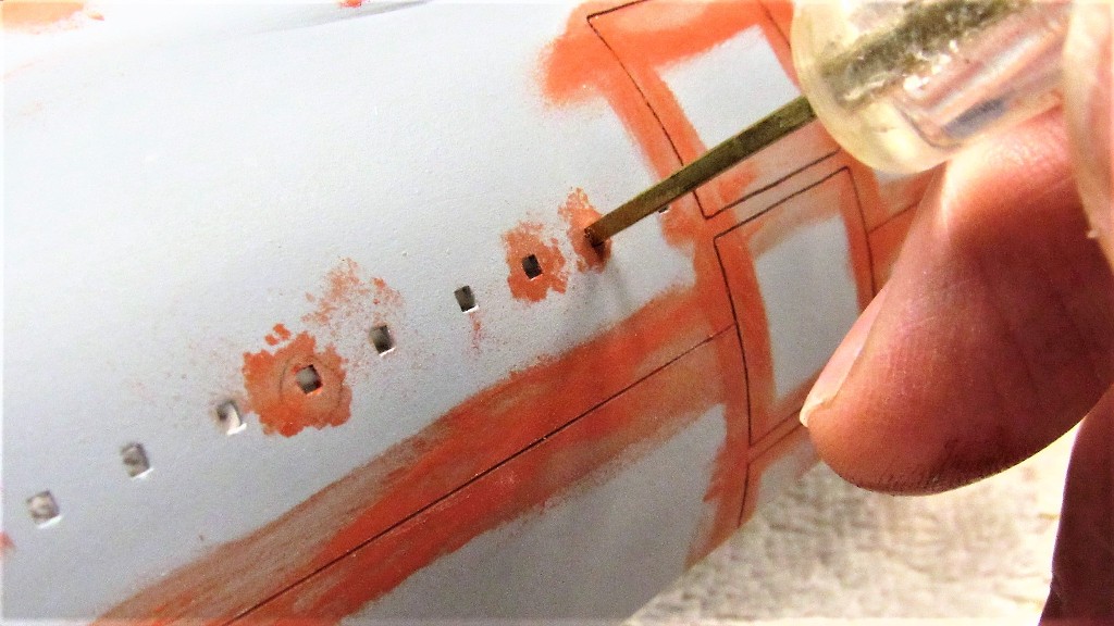
The square limber holes had their outlines tightened up with this tool that forces freshly applied putty to produce perfect, uniform of size, limber holes. The putty was applied with finger-tip or stiff brush, allowed to semi-harden, then the tool was pushed in to give final shape to the hole.

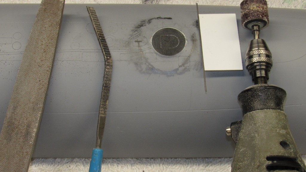
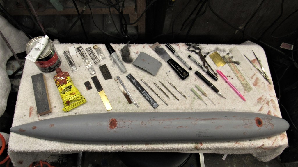
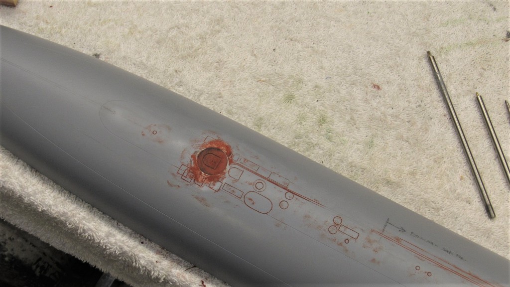
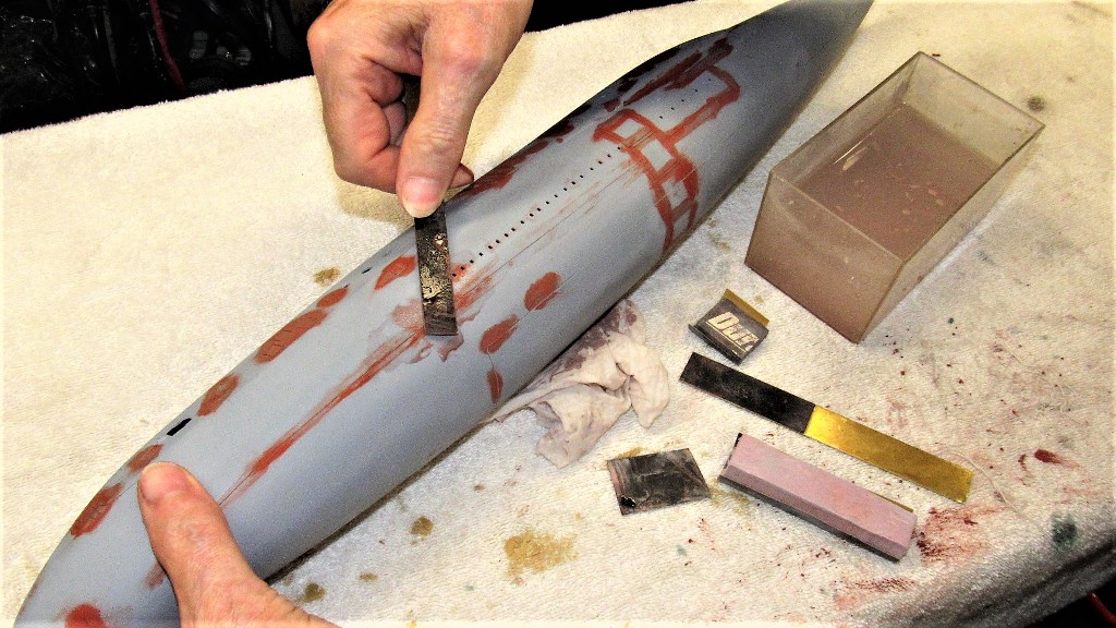
After the scribing and putty work --to fill the inevitable over-strikes during the scribing operations -- The dried putty was sanded flush with the surface of the hull by careful wet sanding with sanding blocks formed from #400 and #240 grit sandpaper glued to strips of .030" brass sheet. Once the hull had dried out I chased out the sanding dust with the scribing tool then scrubbed the surface of the engraved work with a hunk of #000 steel wool.
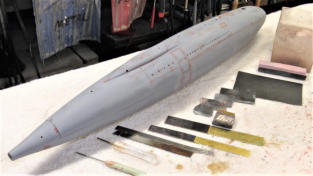
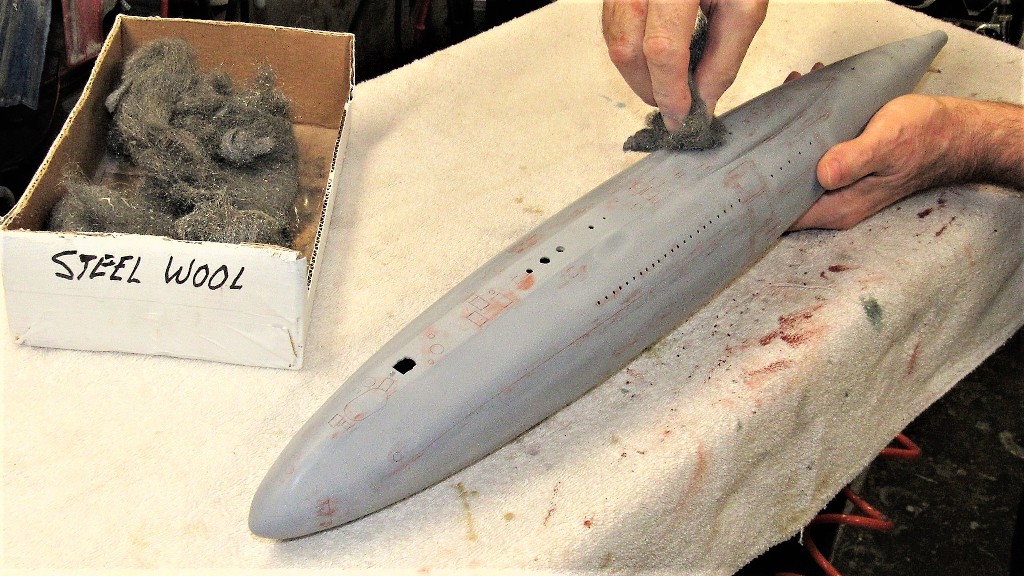
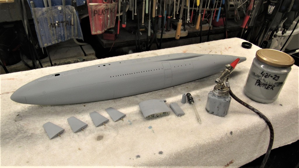
To remove any oil imparted by the steel wool I scrubbed the model with a cloth saturated with a semi-aggressive degreasing agent. This air dried quickly and I proceeded with another coat of primer over all worked areas of the hull and appendages. I'm now ready to glue down narrow strips of polystyrene sheet (or maybe round-stock?) to represent the safety-tracks used by crewmen who would tether themselves to it in order to prevent them being washed over the side in heavy weather (I can assure you, you don't want to be topside, on deck, in foul weather if your boat is a round-hull!).
Leave a comment:
-

Leave a comment: