You know, if your damned fittings kit were still available we wouldn't be in this situation to begin with! :D
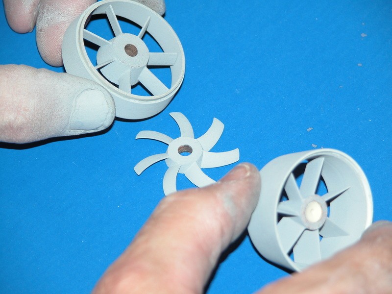
I've attached a sketch that shows the individual pieces in exploded form. Hopefully that clears up some of the confusion. I don't honestly know why he's included the opening for a shaft down the middle, but it seems like enough material for me to work with. Worst case, we improvise. That's half the fun, right?
-
I assume the rotor fits between the two concentric circles. If there is an oilite bearing in the stern of the model, that will keep the shaft from moving latererally. If so, in that case, you don't need bearings in the bores of those two weird concentric thingies if you make them a non-interference fit to the rotor shaft. Just what the hell is the function of those two things, anyway? **** it! Cut them out of there!
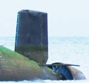
Here's what a proper pump-jet looks like:
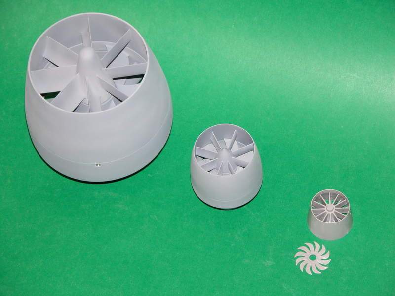
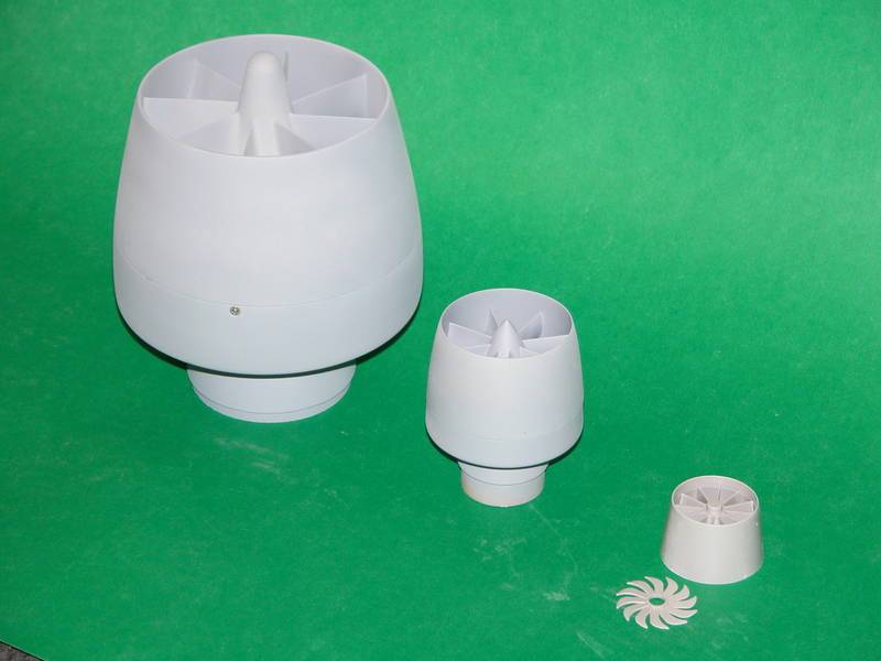
And the PJ I developed for the 1/144 SEAWOLF kit:

Maybe you should check with me before jumping off the deep end on such things?
DavidLeave a comment:
-
Updates!
First, I spent the weekend learning how to silver solder. Several cuts, burns, and a healthy dose of profanity later I now have immense respect for those proficient at the craft. Victor from Scaleships comes to mind with his periscopes and masts. I've experienced his work firsthand and it's truly art.
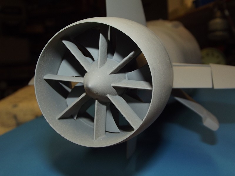
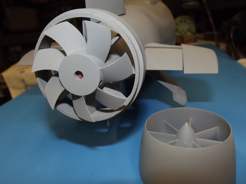
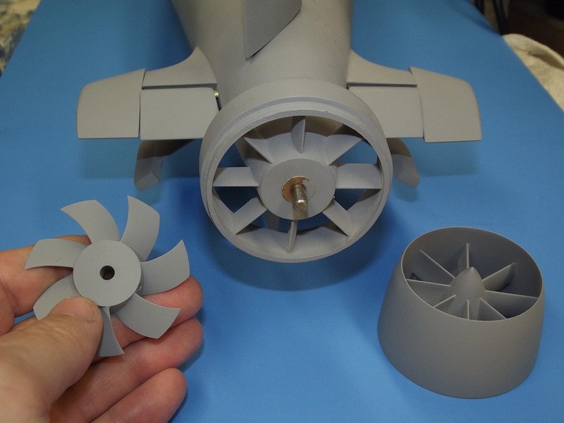
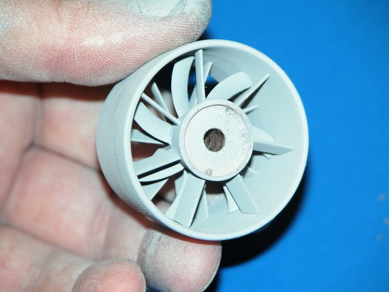
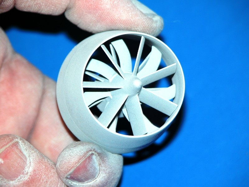
Keeping with the theme of working on the aft-end, I've been thinking about how I'm going to set up my driveshaft. I have a 3/16" polished, stainless shaft that's on its way. I went a different route with the propulsor assembly, and am using some 3D printed parts that I got on Shapeways. My question for the group (I promise not to accidentally post a hundred duplicate pages!) is regarding the center opening of the plastic part and how it will interface with the shaft. The hole down the middle of the printed piece is 4.8mm, so just a shade bigger than the shaft itself. For those not familiar with the plastic that Shapeways uses, it is remarkably durable. Much, much more so than your average model kit polystyrene.
I also have a couple of Oilite bushings that have a 3/16" inner diameter. Given that the shaft will pass through two concentric supports at the tail end, do you guys think it'd be necessary to bore one out to about 1/4" and press-fit an Oilite bushing into that space? I guess my biggest concern would be the spinning shaft creating friction/heat if it were resting directly on the plastic. Then again, this stuff is pretty damn strong as it is. It's not really that much more effort to add a bushing, but I thought it might be worth asking the group before adding an extra step if it was unnecessary.
As always, thank you!Leave a comment:
-
Well I�m embarrassed now.
Thanks Bob. My apologies again to you guys if it was cluttering everything up for everyone else - I was trying my best to troubleshoot it without being a nuisance but my screens were all blank every route I went. It even told me to contact the administrator, and when I did, it told me I didn�t have permissions to contact the administrator. Anyway, it seems to be straightened out now.
-BLast edited by DMTNT; 09-05-2018, 01:22 PM.Leave a comment:
-
Looks like a boatload of duplicated posts when you panicked when they weren't showing up. I approved two that looked to be different (and that Dave replied to) and deleted the rest. I think we're good now, provided you can post upLeave a comment:
-
Here is what I see as postings. I have no way of clearing these and it says I do not have rights to view.
Peace,
TomLeave a comment:
-
My forum settings seem to be buggy, hence the quantity of reposts from me in the last few hours. Apologies, this has been kind of maddening. It's like my posts are posting, but they're not showing up - but they're also being replied to.
To reply to David M's questions and comments in my post about a leak in my SD. First off, the casting flaw in the front cap does indeed run through to the o-ring groove. When you hold it up and look at it eye-level from the side with the flaw, you can see the black of the o-ring.
Second - when I was blowing air into the SD to check the aft for a leak, I was doing so directly into the open front end, with the hoses connected, and my thumb over the nipple that connects to the induction line / float valve in the sail. Were you suggesting a way to leak check the unit would be to blow in through that induction line with the SD submerged and both end caps in place?
As far as I can tell there's no water trapped in the pump. Thank you for the advice.
-BradyLeave a comment:
-
Thank you! Bob Martin posted a video in which he used Archer Fine Details� rivets. They work just like a water slide decal, and they�re not inexpensive at about $17/sheet, but they turn out looking great.
Extending the hull was a matter of obtaining a second Seawolf kit and cutting a length approx 7 inches out of the upper and lower hulls. The upper half was straightforward enough, but on the lower half, I had to use what I could in between the WAS arrays and cut two sections before the hull started to taper. Inside the hull there are six, 12 inch lengths of carbon fiber rod giving her a nice, stiff spine. It became a matter of lining up the various hull segments to where they were close, then backing the gaps with strip styrene and filling in the void with Milliput. Somehow, after all this hacksaw surgery, it still turned out pretty damn straight, and sturdy.
To be truly to scale, I think I�d need to make the model about 1 inch longer and reposition the WAS arrays so they are evenly spaced along the bottom half of the hull, as they are on the real article. I�ve been picking at this project for over a year though, and I decided that what I had looks plenty good enough to me, so I froze the design and proceeded. It�s amazing how well Trumpeter designed this kit to be turned into an RC model. Whether that was intentional on their part or not, I�m grateful either way.
Thanks for the compliments!Leave a comment:
-
-
-
Install about one-pound of fixed lead ballast low in the hull to place (with SD installed) the models C.G. in the middle of the hull. That's it.Put the middle of the ballast tank at the boats center of gravity.
DavidLeave a comment:
-
Jimmy Carter - 1/144
Somewhere along the line I got the bright idea to try and build a submarine. After many dead ends and forks in the road, I find myself with a modified Seawolf hull, a 2� inch sub driver, some very smartly engineered 3D printed pieces, and the whole stack of Trumpeter Seawolf cabal reports.
Gentleman, I am no craftsman, especially when stacked up against your ranks. But, occasionally I am a clever little SOB, and I figure that�s at least got to count for something :)
With the help and talents of those far more skilled than myself, I think I�'ve got all the right ingredients to be dangerous. She�'s not perfect, but at least she looks more like submarine than a banana. I�'ll take it.
I think the next trick will be figuring out how to place the WTC so it�s balanced, especially with the 7� inches of extra hull. I��m open to any suggestions.
Comments and criticism are welcome. Thanks for looking!
-BradyLast edited by DMTNT; 08-14-2018, 01:34 PM.
Leave a comment: