What an improvement, Scott!
David
-
yes, havent forgotten about that but at the moment very little time( just bought a new house ) what i can spare, i spent on finishing the MIKE at the moment
Beluga Video: https://www.youtube.com/watch?v=35qkTYwhBakLast edited by JHapprich; 10-02-2018, 04:32 AM.Leave a comment:
-
what a sexy hull! there are some guys here in germany / brandenburg having build two belugas of about 2 metres each with onboard compressor etc. all the cool stuff. very interesting boat! regards j�rgLeave a comment:
-
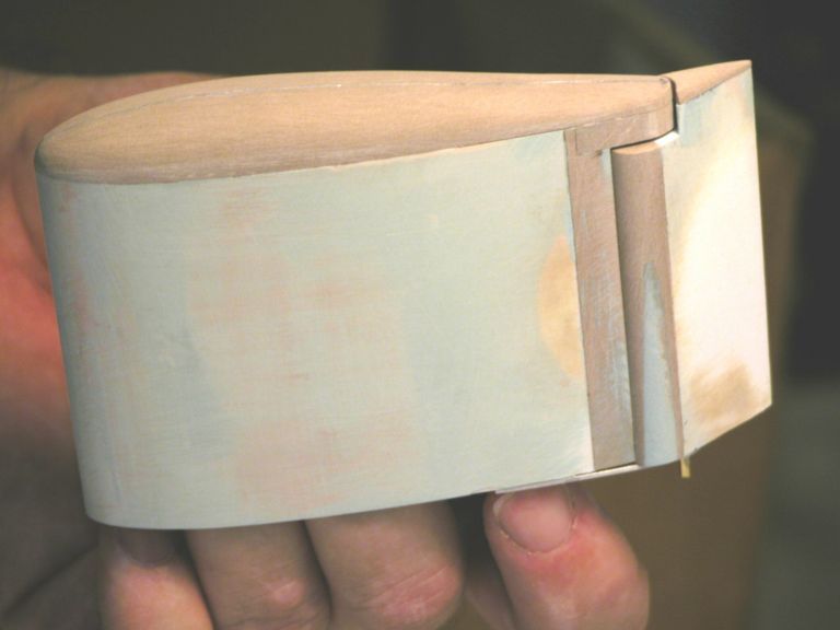
This is the test hull that I laid up last week. Its been sitting around for 7 days getting hard. Its also an experiment to see if the new gel coat that I ordered will really make any difference. And yes; it does. No pin holes, no blemishes and no warping. All in all it came out pretty well. Onward to the Albacore!
Leave a comment:
-
Very interesting. Fitting a second angle keeper is genius. I also like Mark's solution to provide counter rotation. Looks like a really interesting project.Leave a comment:
-
Leave a comment:
-
The dorsal rudder works independently of the rudder (but some mixing of the rudder and dorsal rudder is a possibility, but does not measure roll). Has its own servo and angle-keeper, that angle-keepr oriented to detect roll, not pitch. Here's how the linkage works on my most recent 1/60 ALBACORE:
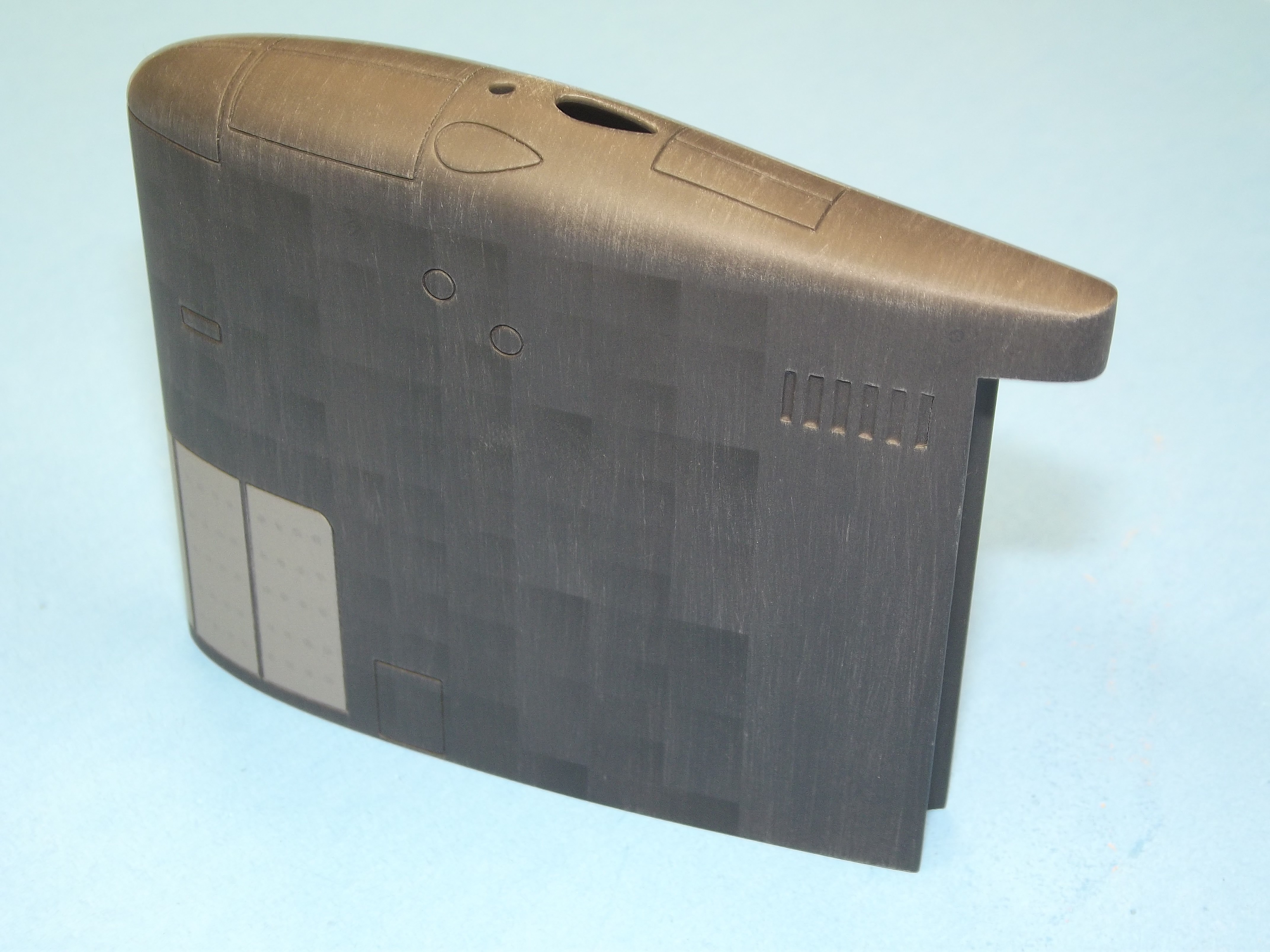
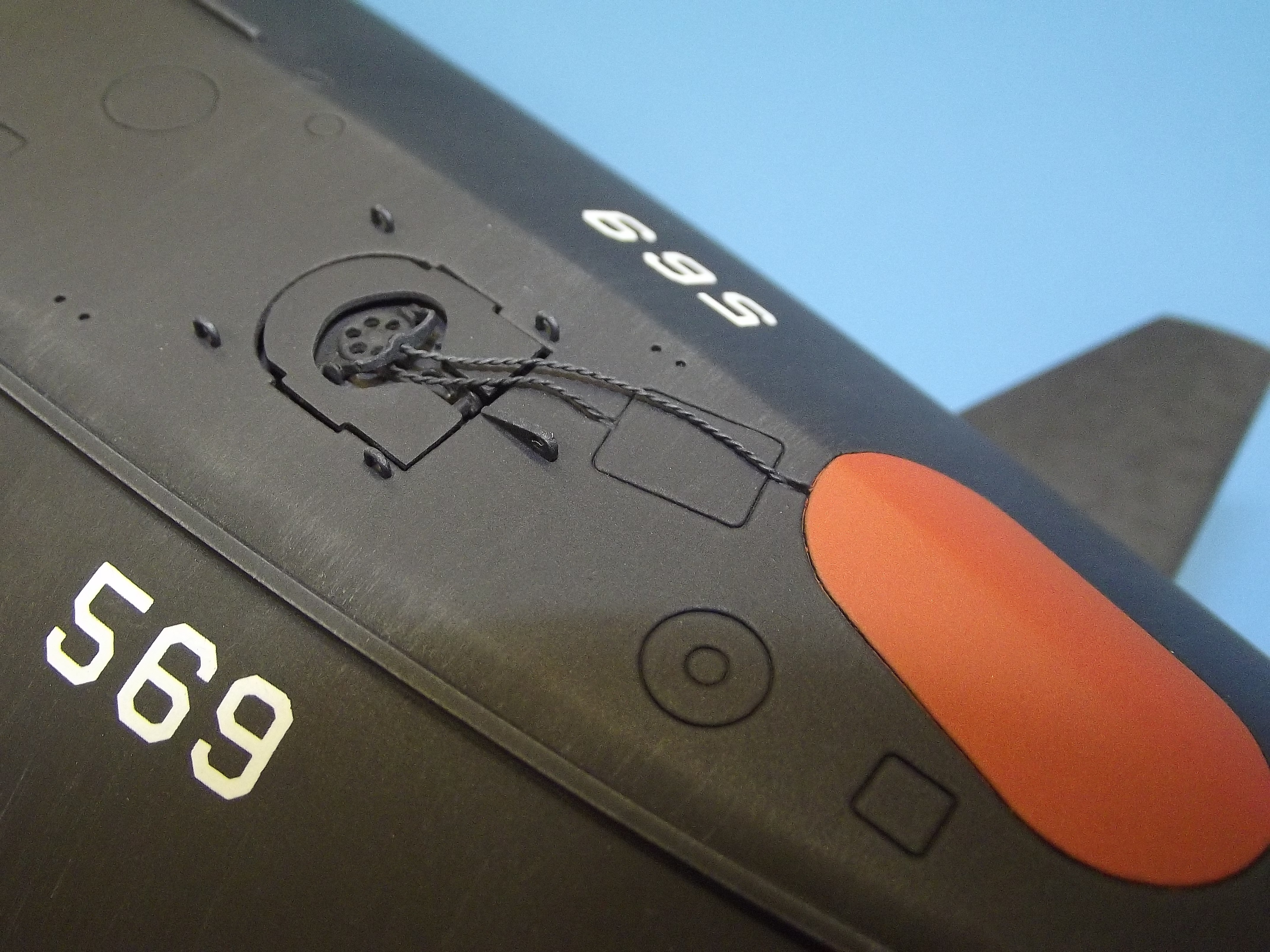
In an e-mail you asked about the fairlead over the two escape hatches. More detail on that item:
Here's some video showing how effective the dorsal rudder was in eliminating the 'inboard roll'. Even in tight turns:
DavidLast edited by He Who Shall Not Be Named; 06-20-2018, 12:32 PM.Leave a comment:
-
"What the world needs now, Scott, is a 1/96 ALBACORE! We�ll breed these two and see what happens!"
Was that dorsal rudder coupled to the rear steering or a seperatly operated thing? If its coupled - which way does it swing, with the commanded rudder direction or against it?Leave a comment:
-
I've certainly made you and Bart wait long enough! I got caught up in preparations for the Groton fun run. Now, with that out of the way I can catch up on things. Certified the SD's yesterday. Today I box them up and should have them underway this afternoon. The new LPB scheme works like a charm.
DavidLeave a comment:
-
Wow. Can't wait to see this. Thanks for the kind words (and the kick in the arse). I did, in fact, pull it out of the mould way too soon. Again, I couldn't wait to have a look at it; my total experience of epoxy layup is encapsulated in this boat and I had no idea how it would come out. Its all new and all exciting. Thanks for your generosity, in word and deed. It is very much appreciated.Leave a comment:
-
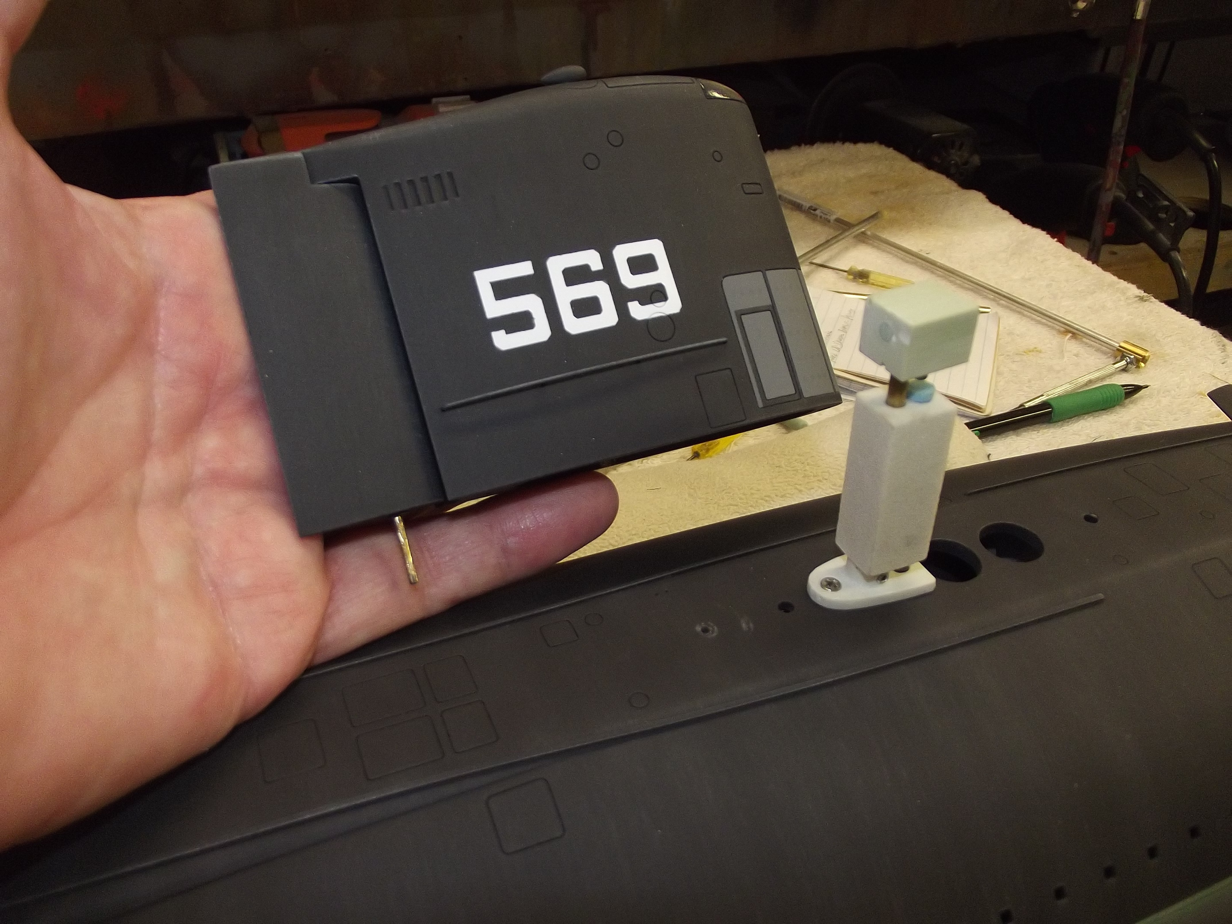
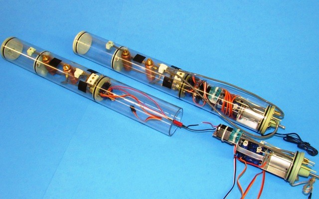
As the limit switch is mounted to the after ballast bulkhead, deep within the after dry space, making it inaccessible, it became necessary to run two wires from the switch to make up to a plug that projected slightly from the after end of the cylinder. The smallest two-pin connecter Deans makes was used to interconnect the wires between limit switch and removable motor bulkhead.
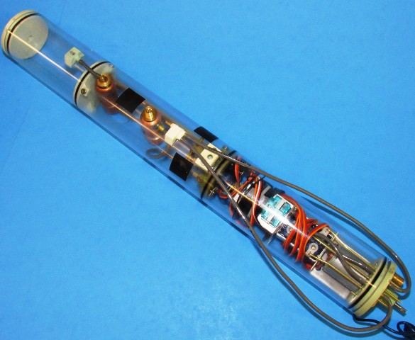
Shown is a buttoned up BELUGA SD above an SD with its motor bulkhead pulled out to show the wires and Deans plug that permits quick and easy separation. As you can see, there are two leads running back from the motor bulkhead � each equipped with plugs: the three-wire lead between ballast servo and fail-safe circuit; and the two-wire lead from the servo mounted limit-switch to the LPB and power cable.
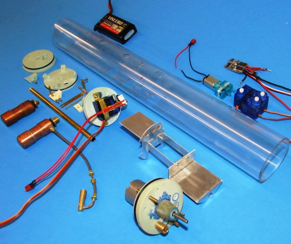
This exploded presentation of the basic SubDriver components illustrates how things fit together. The only mechanical fasteners are the eight flat-head screws that hold the ballast bulkheads in position within the cylinder, and the two small flat-head machine screws that hold the vent valve body atop the ballast tank.
The devices upper right are the three control surface servos (stern planes, bow planes, and rudder); electronic speed controller (ESC); and LPB.
Not shown is the receiver, angle-keeper, failsafe, and mission switch (be it toggle or magnetically actuated).
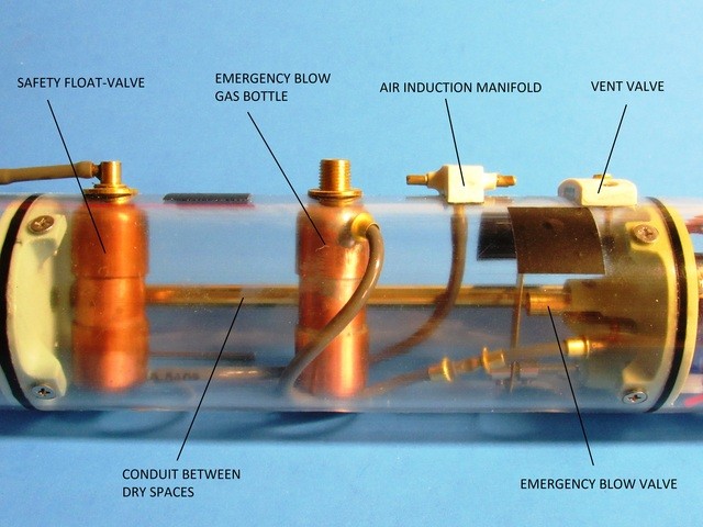
This is the typical arrangement of components within an SD�s ballast tank -- pretty much the same for all sizes of the SD. The floodable volume of the ballast tank is set by the distance between the two ballast bulkheads.
The conduit running between the forward and after dry spaces permits passage of the power cable from the forward mounted battery to the devices within the after dry space; the emergency blow gas bottle is a back-up and only comes into play if the fail-safe triggers (loss of signal or low battery voltage) an emergency blow.
The normal blow servo position -- established during set-up of the transmitters ch-4 end-points -- is just enough to engage the LPB (be it through electronic switch or mechanical limit-switch). The emergency blow position -- established during fail-safe set-up -- produces additional servo travel in the �blow� direction, enough to engage the gas blow valve.
The vent valve dumps the air from the ballast tank when the ballast sub-system servo is commanded to �vent� from the transmitter. The vent valve, in the �neutral� and �blow� positions, remains closed; the air induction manifold connects the SD dry spaces and snorkel induction lines to the LPB suction side through external and internal flexible hoses.
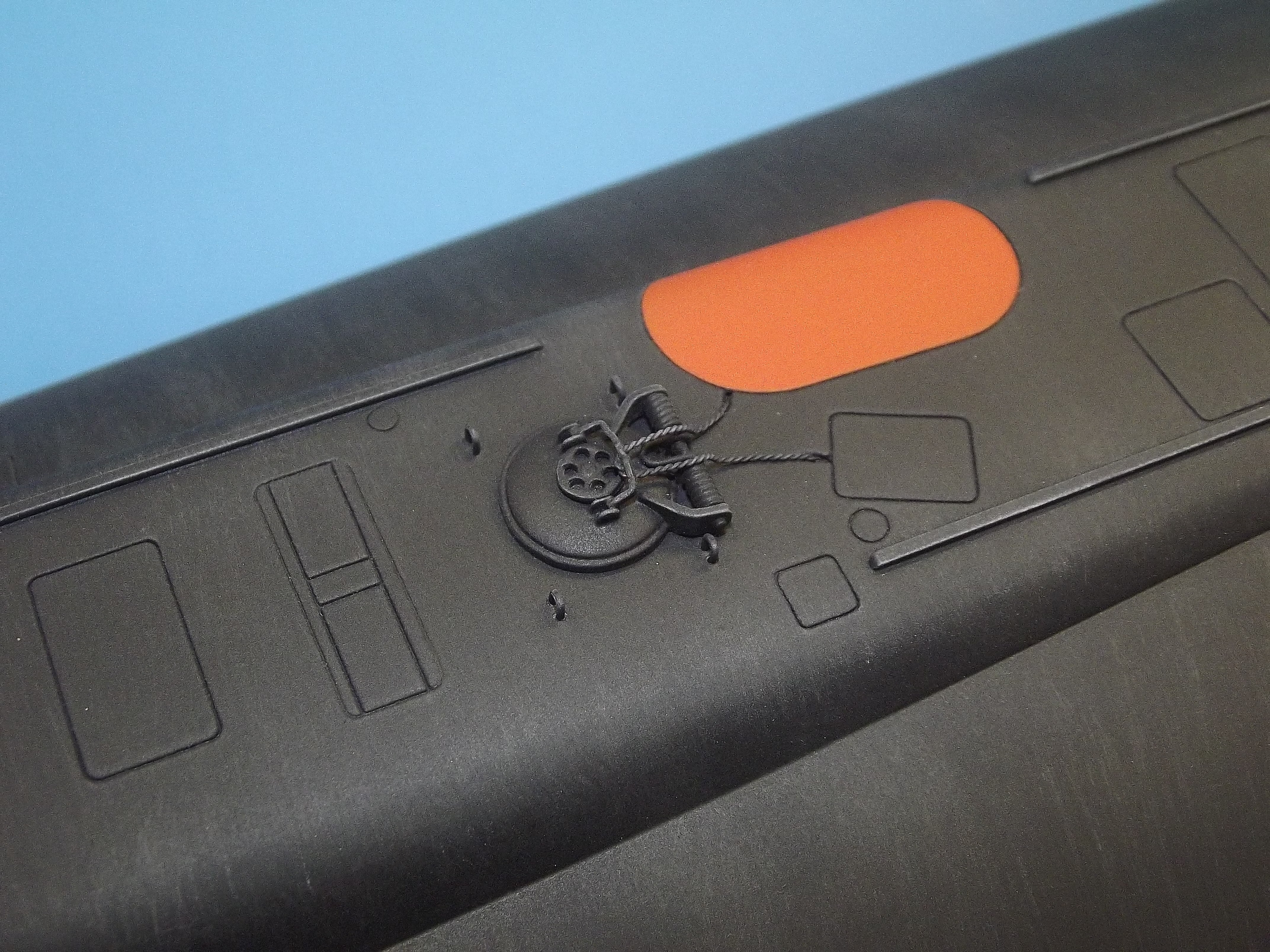
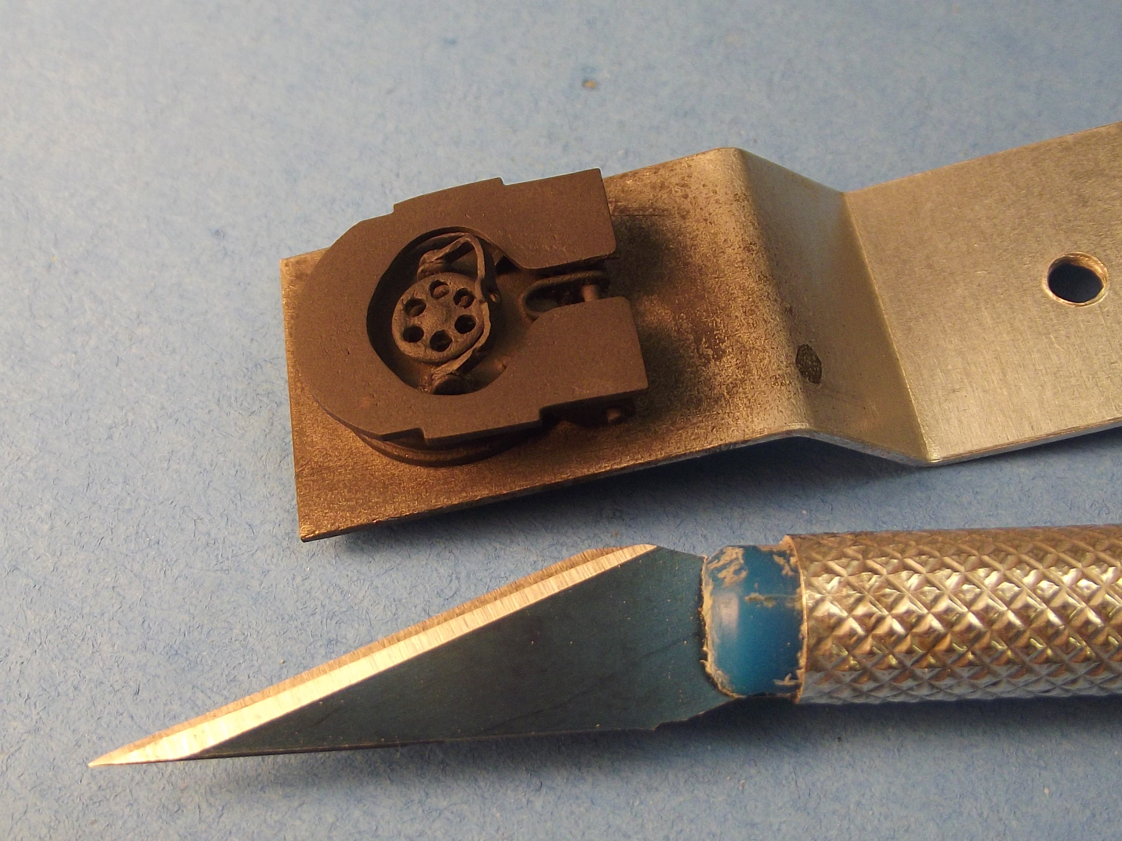
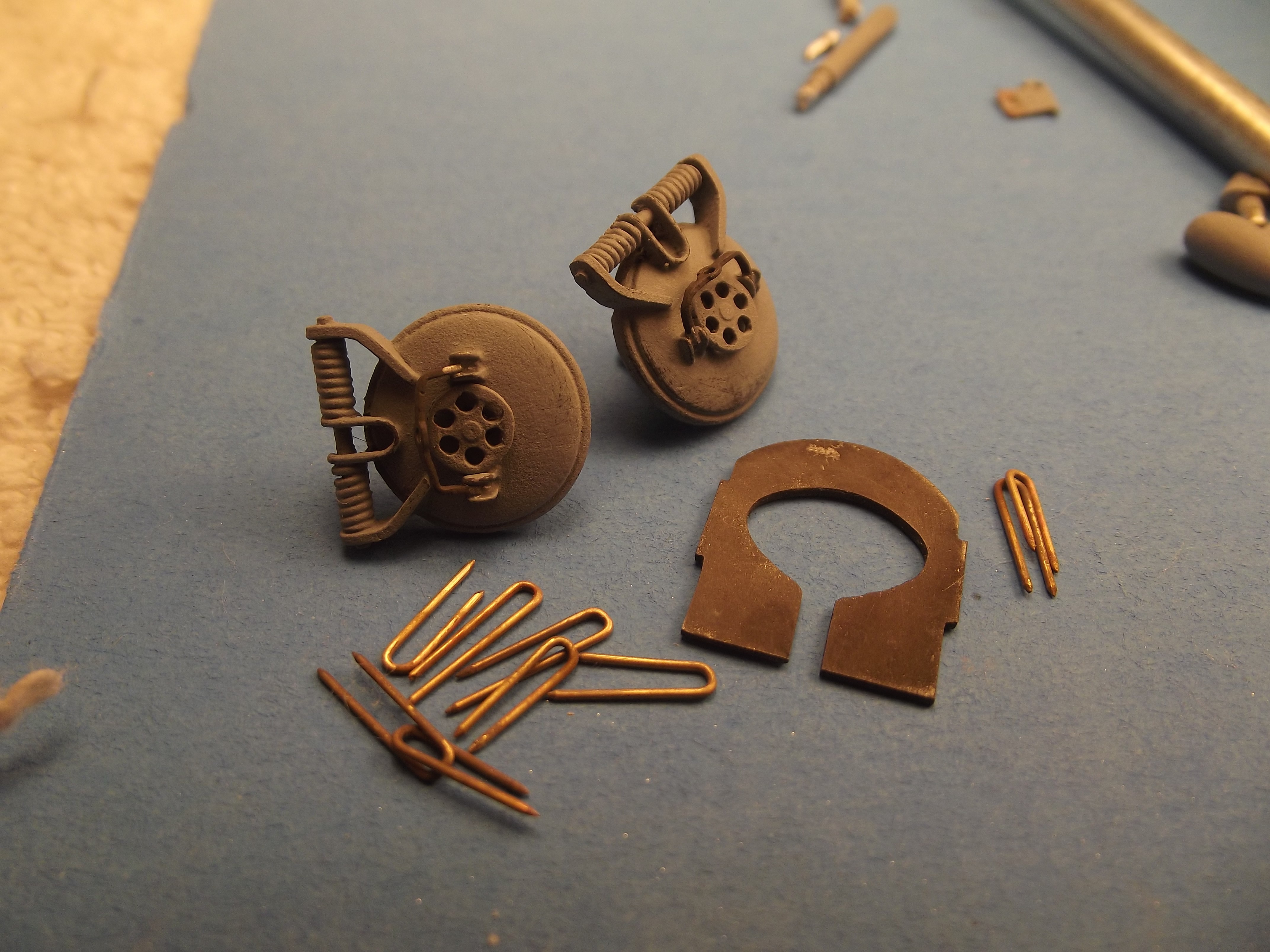
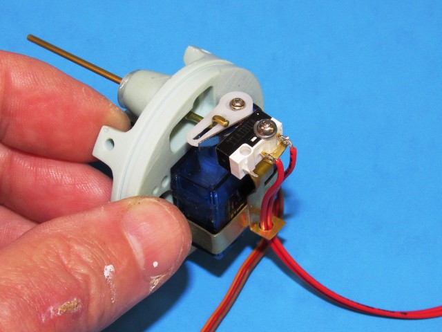
Two close-up looks at how the servo bell-crank works the limit-switch. Simple, tough and cheap!
Fine adjustment between servo bell-crank and limit-switch arm is achieved by rotating the switch on its single mounting screw.
The servo pushrod passes through a watertight seal set within the after ballast bulkhead and extends forward into the ballast tank. A linkage arm translates the fore-aft motion of the pushrod into a rocking motion that opens and closes the ballast tank vent valve. This same linkage arm, in the extreme �blow� position (fail-safe activation) makes contact with the stem of the emergency gas blow valve, releasing gas into the ballast tank, quickly surfacing the boat.
Normal (LPB) and emergency (gas) blow options. Just like the big boys do it.
A complete 2� SD sized to fit the tight confines of Scott�s 1/96 BALUGA r/c submarine.
I calculated the weight of water needed to fill the ballast tank for that particular model by simply weighing the upper hull (you can do that without conversion as the specific gravity of a typical GRP item is close to that of water), reducing that a third � accounting for the portion of upper hull sitting below the designed waterline (a big thank-you to Scott for lightly scribing the waterline into the upper hull part).
That gave the weight of water needed to get the model from surface to submerged trim. But, one has to figure in the loss of useable volume within the ballast tank by structures such as the emergency blow bottle, safety float-valve, and conduit. And I had to take into account that about one-quarter of the ballast tank will sit above the waterline � that�s lost displacement, reducing the buoyant force exerted by the SD in surfaced trim.
I plugged in fifteen-percent extra ballast water as a fudge factor.
From all that and a bit of geometry the length of the ballast tank needed to hold the correct amount of ballast water, needed to counter the displacement of all above waterline structures, was established.
The forward dry space had to be kept as short as possible so was sized to accept 7.4-volt, 1300mAh lithium-polymer batteries. I figure two of those, one stacked above the other, would provide the capacity needed to run this thing for over two hours � even those with a lead foot would get around an hour of hair-raising submarine driving. Yes! Guilty!
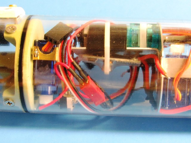
Demonstrating how tight things get in the after dry space of the 2� SD. Note how little room is available for the receiver, angle-keeper, and fail-safe. The multi-tasking KMC battery link monitor (BLM) doing the job as the loss-of-signal fail-safe, protecting the Lithium-polymer battery, and recording signal loss events during the cruise. These devices yet to be installed. You see here, to good advantage, the small Deans connector that permits complete separation of the motor bulkhead (with all its mounted devices) from the SD cylinder.
I�m a strong believer in accessibility (learned from my Torpedoman days in the navy). I engineer my stuff so it comes apart easily, without resort to hammer and chain-saw. The only thing glued permanently to the cylinder is the two manifolds. Other than that all one needs is a Phillips screw-driver and it all comes apart for service, adjustment or repair.
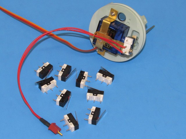
Amazon is our friend!
I found these little limit-switches selling for about twenty-cents a pop! I got a bag full. The only thing I had to do was bore out a larger hole to pass the single 2-56 X 3/8� machine screw used to mount the switch to the servo bracket.
David
Leave a comment:
-
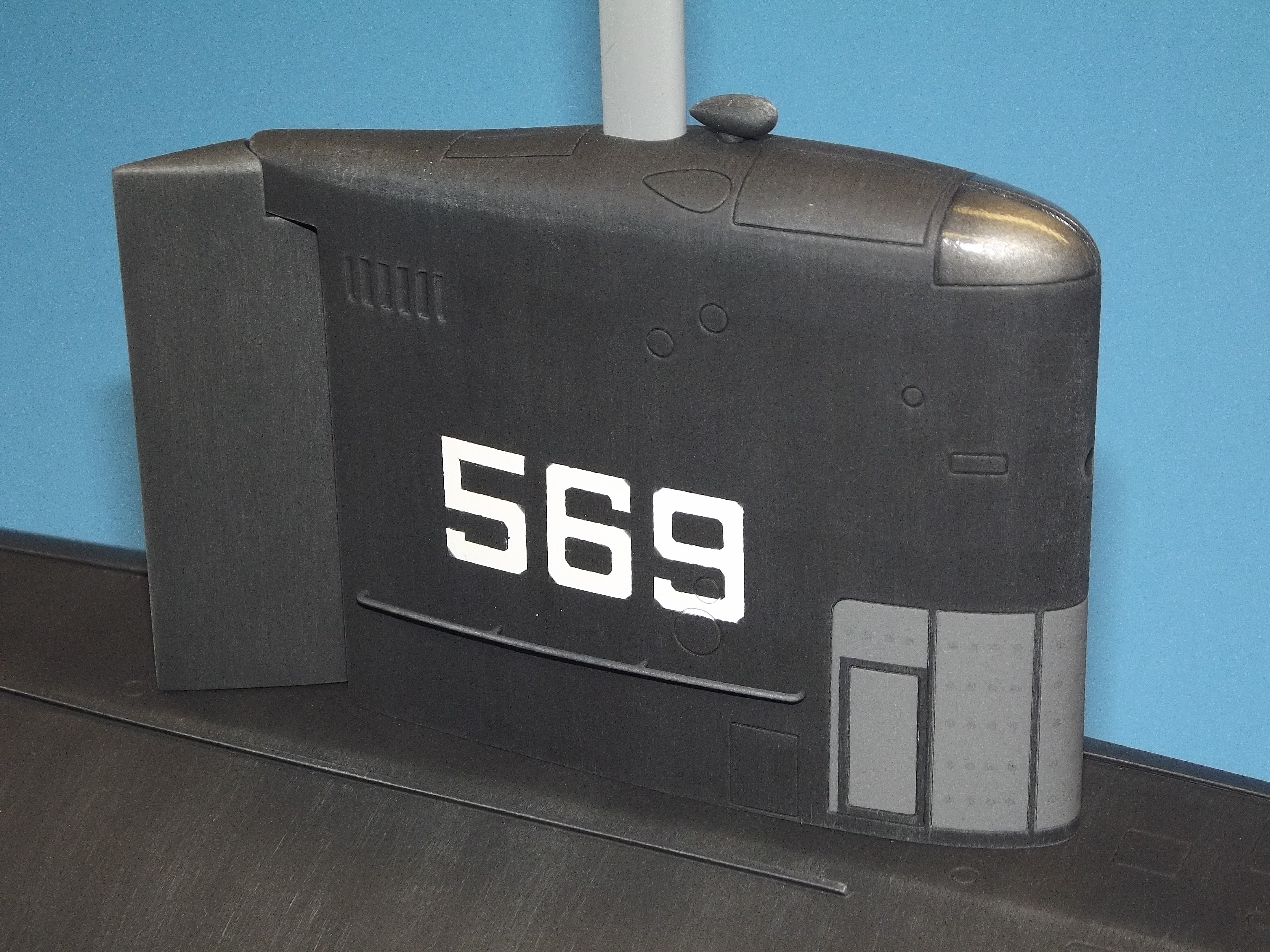
Scott Terry sent me a very smart looking 1/96 BALUGA kit. This, the latest GRP and resin r/c submarine kit from Scott is a testament of his quickly advancing skills � this is number three of his line of 1/96 submarine kits.
As with his ROMEO and ZULU kits, Scott and I bartered one of my SubDrivers (SD) � called water tight cylinder (WTC) in some circles � for one of his BALUGA kits.
I�m presenting here the work I�ve done to produce BALUGA SD�s. In the future these might be available through the Nautilus Drydocks should Scott go big-time with his kit offerings. https://www.rc-submarine.com/
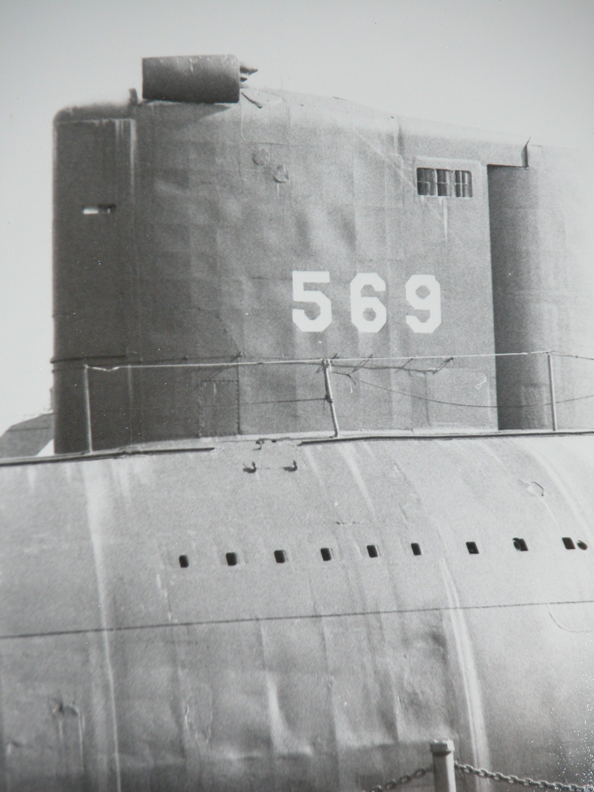
Below is a look at the actual BALUGA sometime during its operational career. Not a combatant, this unique boat was a Russian research submarine, much like the American ALBACORE that preceded it; the BALUGA�s mission to explore optimized hull form, means of boundary-layer reduction, and advanced propulsor configurations.
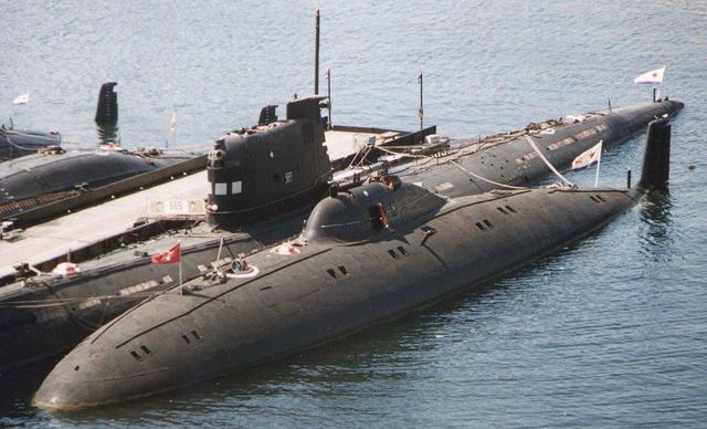
Here�s a quick look at the history of the BALUGA: https://en.wikipedia.org/wiki/Beluga-class_submarine
For an exhausting discussion about the kits creation and Scott�s build-up I recommend you give the following site a good read-through:
https://forum.sub-driver.com/forum/builder-threads/123228-1-96-project-1710-belugaPrepare for a long sit-down at the computer!
Don�t know the source of these drawings, which I pulled off the internet. if I knew I would give this guy full credit. Someone out there � give me a clue. The drawing appears to be a very close graphical presentation of the boats shape and details. I assume this is the same document Scott employed as he put together the masters.

I made three SD�s for the BALUGA. One for Scott, one for me, and one for Bart (I�m chumming the waters for one of his outstanding 1/144 AKULA kits). The small diameter and tight tapers at both ends of the 1/96 BALUGA forced me to employ a 2� diameter SD of relatively short length, as seen below.
What the world needs now, Scott, is a 1/96 ALBACORE! We�ll breed these two and see what happens!
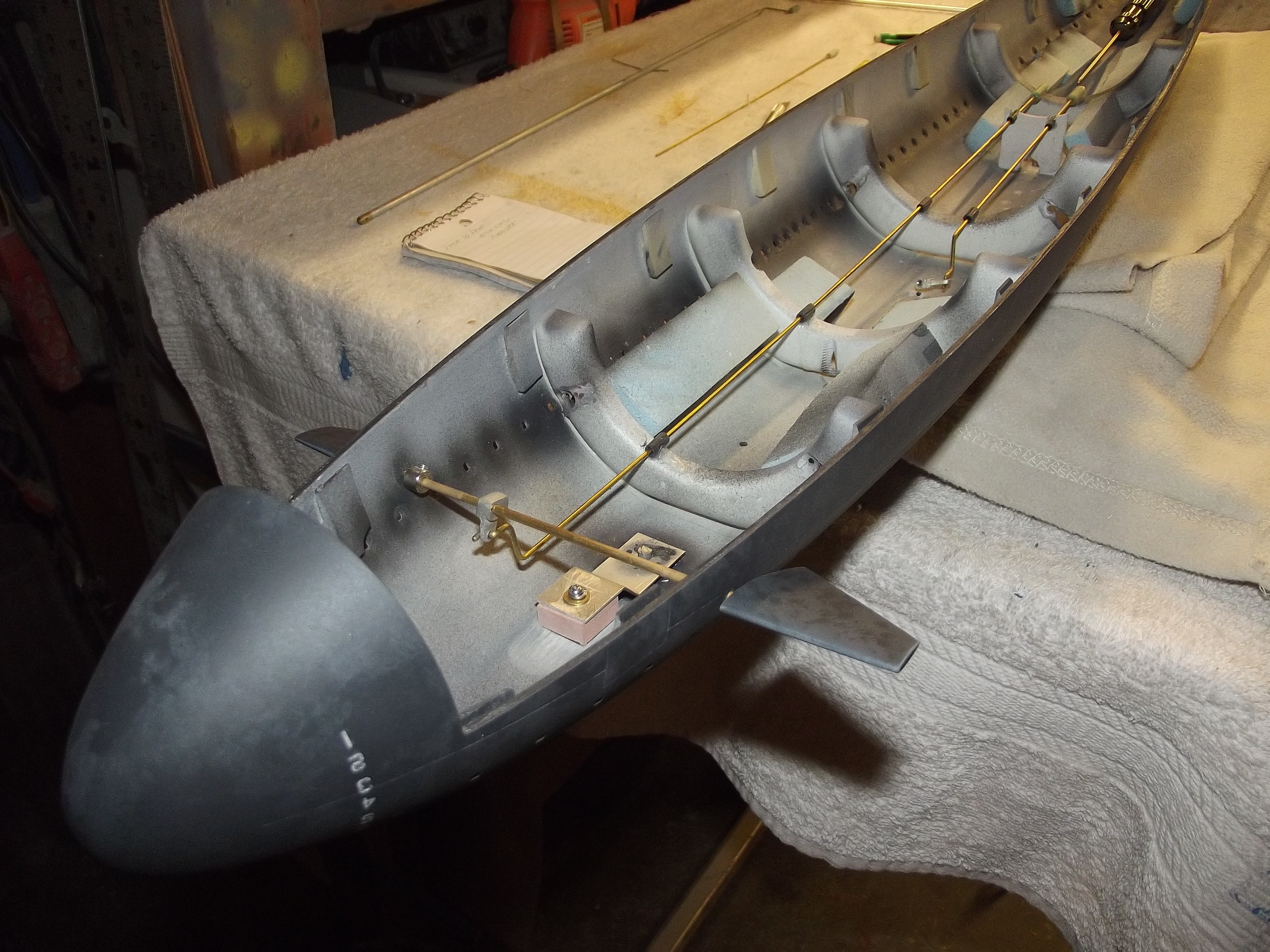
One nice surprise when I opened the box from Australia was the cast resin, hollow tail-cone with attached horizontal and vertical stabilizers. This will save a lot of work! Looks like Scott sprayed in some auto-primer into the upper hull tool to become the first layer of the gel-coat -- a neat trick which fillets the high relief items within the tool cavity and produces a solid gray color to the eventual GRP part. Only the upper hull was given the gray primer treatment. Which makes sense since the lower hull is devoid of any high relief features.
Internally the glass work is a bit sloppy, indicating he used too heavy a glass cloth/roving in the lay-up. Also, the two hull halves have warped open a bit -- the impatient sod pulled the parts from the tools too soon! I�ll address that little wrinkle later with a heat gun, another lamination of glass cloth, and an alignment jig to hold each hull half to proper diameter as the resin cures.
What a neat looking little rocket this thing will be! Other than the above *****ing, I love this kit!
OK. That�s the background. Now, on to my end of the project: the BALUGA SubDriver (SD).
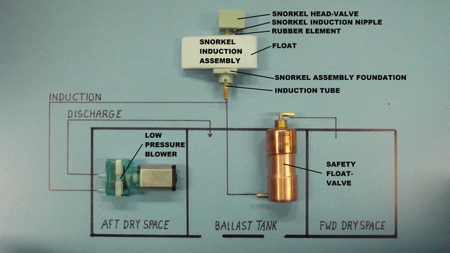
The Semi-ASpirated (SAS) method of ballast water discharge differs from other model submarines in that the function is more faithful to that used by real military submarines. During the �blow� operation low pressure air, compressed by a low pressure blower (LPB), initially scavenges air from within the pressure hull --for only a few moments, enough to poke the snorkel valve, located in the sail, above the water�s surface. Then, from atmosphere, as the float operated snorkel takes in air to break the partial vacuum within the SD, the blow is completed, emptying the ballast tank of water, getting the model submarine up to designed waterline.
The compressed air, no matter its source, is introduced to a �soft� type ballast tank, one in which open flood-drain holes at its bottom prevents any significant differential pressure between the tank and the outside water no matter the depth -- the slightly elevated air pressure within the ballast tank during the blow (be it LPB or gas) is enough to push out ballast water, lightening the boat.
The key to this ballast sub-system is, of course, the pump used to send compressed air to the ballast tank. Years ago my old partner, Mike Caswell, identified sources for these little motor driven air-pumps. In operation the LPB works in concert with the SD�s ballast servo off a Y-lead from the fail-safe device (be it an ADF2, BLM or other type fail-safe device). A prime requirement of the air-pump was that it not be a true positive-displacement type. As water would sometimes get into the pump (leaking snorkel valve for example) it had to employ elements that would �give� so that the mechanism would not be water-hammered when presented with a non-compressible fluid. Diaphragm type pumps fit the bill perfectly -- as I found during initial testing: they pump both air and water with equal enthusiasm, and without damage.
The ballast tank vent valve is normally closed. However, when the �flood� command is sent from the transmitter, the ballast servo opens the ballast tank vent valve, and the LPB sits there doing nothing, and the tank floods through the always open flood-drain holes at the bottom of the ballast tank. When the �blow� command is sent the ballast servo keeps the vent valve closed and the LPB motor starts up, drawing air into the induction line -- either from the interior of the SD or atmosphere � squirting the compressed air into the ballast tank, discharging its water through the flood-drain holes.
In the past I employed the excellent KMC electronic pump-controllers. But, today, I�m toying with a simple limit switch (slaved to ballast servo position) to turn the LPB pump on and off.
The mock-up below shows both the function and the actual devices that comprise the SAS ballast sub-system. The safety float-valve prevents any leak in the external induction line from pushing water into the SubDrivers interior.
The vent valve, ballast sub-system servo and associated linkages have been omitted for clarity.
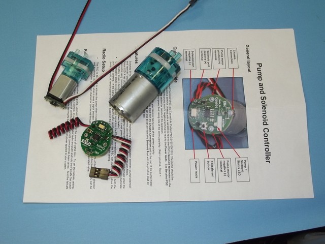
Before Kevin�s little purpose built LPB motor-controllers we had to settle for the big-ass motor controllers provided by other vendors. Not a problem with the larger cylinders, but the relatively small 2� diameter SD -- where there is little volume to spare for devices � is where Kevin�s little MPC�s saved the day. Note the very small foot-print of these motor-controllers.
The KMC motor-controller takes line voltage to run the pump, and that current is controlled by the device as directed by either the transmitter or fail-safe through a standard receiver lead that plugs into the receiver channel of choice (typically ch-4). The MPC shares its signal with the ballast sub-system servo through a Y-lead. The MPC and servo work in concert.
These units can be had through Nautilus Drydocks.
https://www.rc-submarine.com/product-page/mini-pump-controller
https://www.rc-submarine.com/product-page/pump-and-solenoid-controller
And some of those early Chinese electronic switches simply did not work! I�ve been using the KMC devices for over ten years and love their reliability and ease of integration with the LPB�s I use.
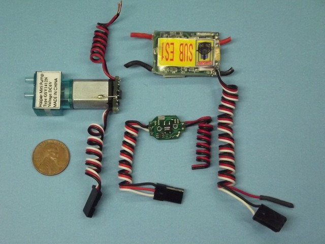
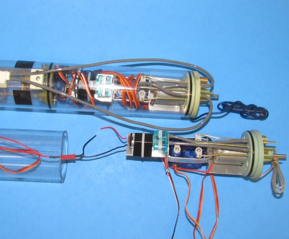
Two of the smaller LPB�s, the one to the left equipped with the KMC MPC. To the right of that is a LPB configured for limit-switch control. Note that spark suppression capacitors were added to the motor not using the MPC. The MPC circuit has spark suppression built in.
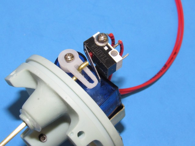
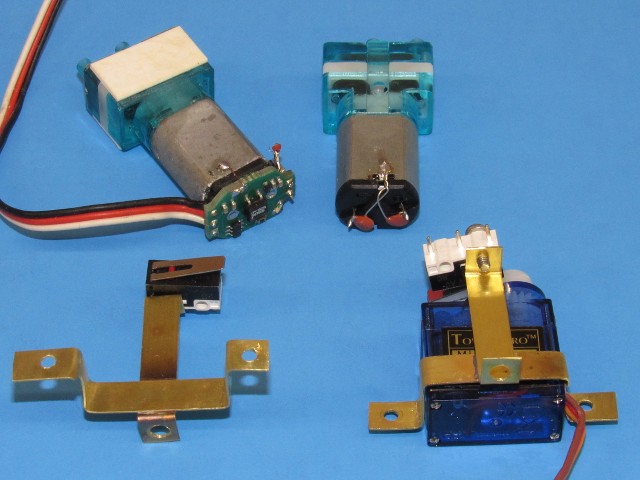
The servo driven limit-switch replaces the MPC. It�s this mechanical switch that now turns the LPB�s motor on and off -- the servo bell-crank, acting as a cam, closes the switch when the servo moves slightly to the �blow� position. The switch remains open in the �vent� and �neutral� positions.
A special servo bracket assembly jig insures consistency of limit switch position in relation to the servos bell-crank for all servo brackets manufactured. Here you see the servo brackets with mounted limit-switches. Note the long switch arm, positioned near the tip of the servo bell-crank.
Installation is easy: I slip the servo bracket over the servo, and screw the unit to the dry side of the after ballast bulkhead and I�m in business.
There is enough spring in the brass strip that holds the limit-switch to the bracket to permit over-travel of the servo, which occurs when the fail-safe takes over and drives the ballast sub-system servo aggressively to the emergency �blow� position. Normal blow does not flex this strip, but over-travel from the emergency blow bends it, like a leaf-spring, back enough to prevent stalling the servo.
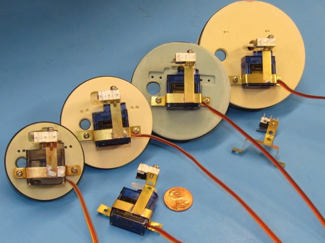
The clever thing, from a production standpoint, about the servo driven limit-switch, is that the same servo, servo bracket, and attached limit-switch finds application on all the different SubDrivers I manufacture. SD Cylinder diameters of 2�, 2.5�, 3�, and 3.5� are shown below.
Leave a comment:
-
The gear box looks good, but keep in mind that there has to be a sizable amount of 'slop' between the gears as they are working in an incompressible fluid. If too tight your gears will be water hammered at speed and will bind up, or at best, will present an unreasonably high torque load on the drive shaft.
Just about done with the BALUGA SD's. Should have them done and tested mid-week. Then off to you and Bart.
DavidLeave a comment:


Leave a comment: