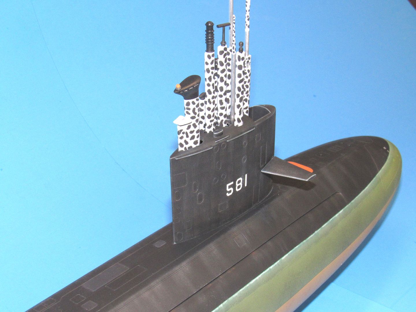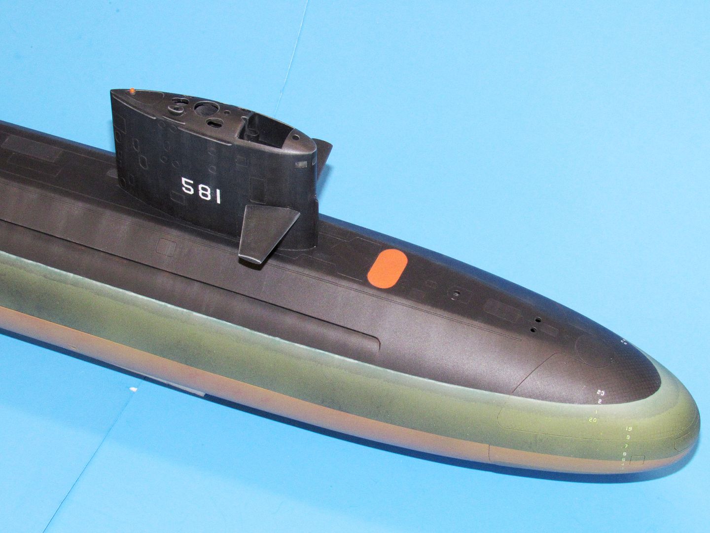
The upgraded SWM 1/96 BLUEBACK kit

Collapse
X
 
  • Time
  • Show
Clear All
new posts
  • He Who Shall Not Be Named
    Moderator
    • Aug 2008
    • 12309

    #16


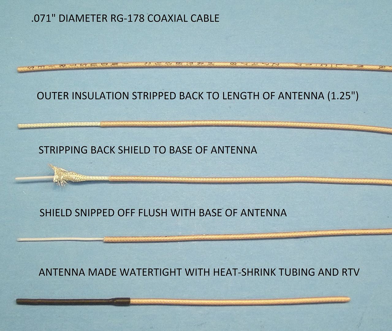
    It’s the job of the coaxial cable to shield the conducting central wire between antenna and receiver – this is done through a grounded braded metal shield that surrounds the central conductor. Remove the shield from the conductor and you have an antenna. And that’s what the above photo demonstrates: the steps taken to turn the end of the coaxial cable into a 2.4gHz full-wave antenna.

    A thorough discussion on how to move the antenna off-receiver to another location is covered here:
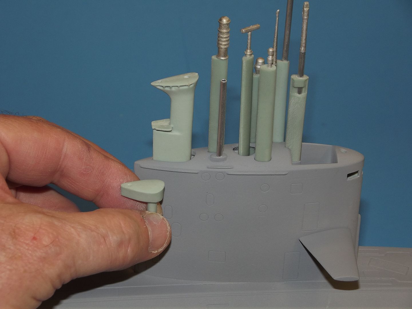


    On the many occasions when I operate the model with most of the masts left in the field-box, I cover the gapping snorkel mast hole with this plug. The top of the plug mimics the contour of the snorkel mast top. It too is detailed with the same amber submarine identification light as the full-up scale snorkel mast.

    I seldom operate an r/c submarine with all its masts up. Besides not being scale (rarely are they all deployed at the same time on a real submarine) those projecting items simply invite disaster through handling or collision.
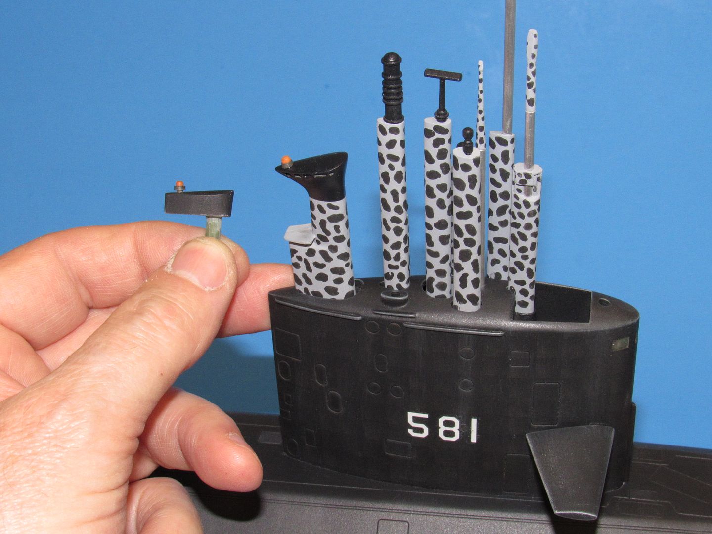


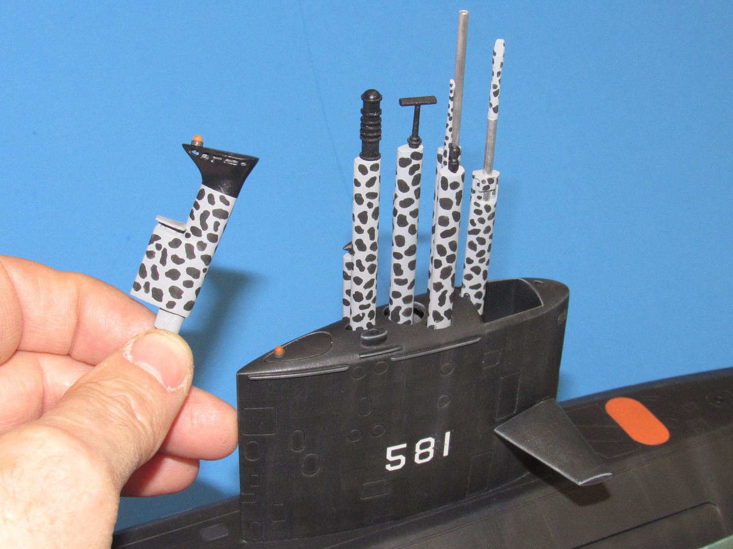
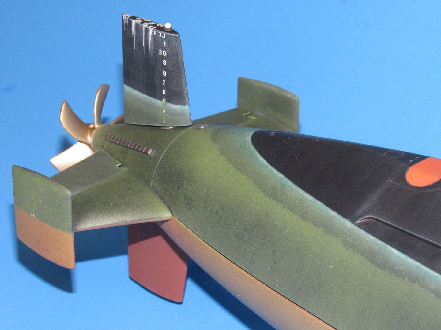
    Jumping ahead a bit to show the completed model parts here. You can see to good advantage here some of the weathering effects applied to the model to give it that ‘real’ look that’s so important to me as a kit-assembler.

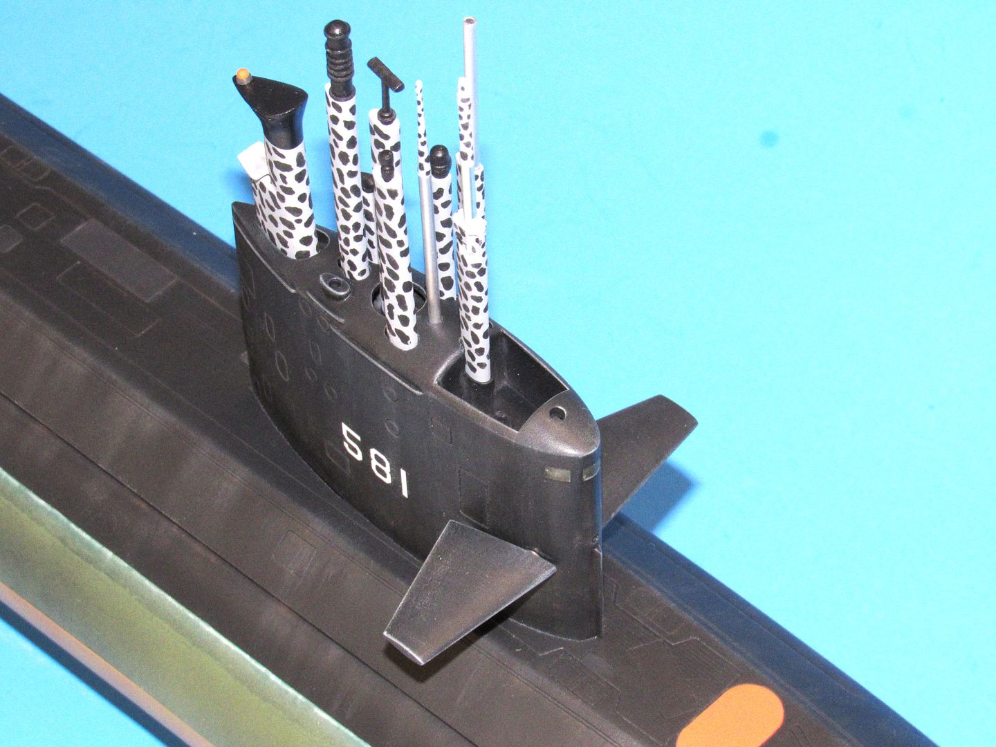
    As you can imagine, it’s a fool’s errant to drive this r/c submarine around recklessly with all those delicate masts in place … and yes, I’ve been described as being a bit aggressive when my submerged boat finds itself in a target rich environment. So, the array you see here is for show only: when I put this beat in the water I’ll operate with only the #2 scope raised atop the sail – as that’s simply piece of aluminum tube topped with a scope head, it’s no big deal if I bend it back during a patrol. (Yes, spare #2 scopes are in the field-box).
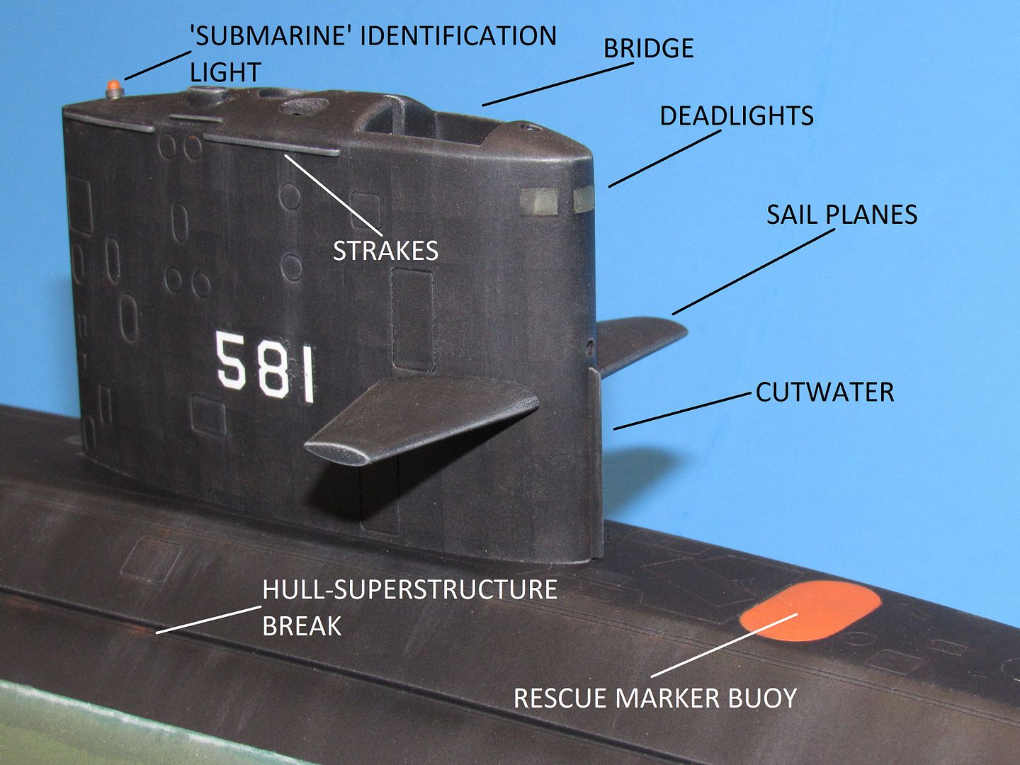


    The SKIPJACK, BARBEL, and the BENJAMIN FRANKLIN class submarines were the last American combatants to provide dead-lights (windows) set within the leading edge of the sail -- a relic from days of old when a submarine could get caught on the surface in bad weather. A portion of the free-flooding space within the sail, adjacent the high mounted bridge cockpit, was set aside for those moments when green-water would break over the sail and drench the bridge. Post-war boats had no steering gear or other ship-control gear within this enclosure (other than a phone-talker jack, and maybe a simple chart-table), it was just a place to duck when required, but with an outside view. Now, in a navy devoid of any combatant submarines tied to the surface by air-breathing machinery, sail dead-lights are a relic of the past and no longer provided in American combatant type submarines.

    But, on a model depicting a boat that featured them, it’s almost a crime not to incorporate this eye-catching feature on the display. Most of us are happy simply simulating the glazing with paint and gloss-clear-coat to suggest such windows. However, David Manley showed us all a neat way to quickly, and realistically, represents submarine sail dead-lights – honest to goodness transparent deadlights. And a means to simulate them quickly and easily.
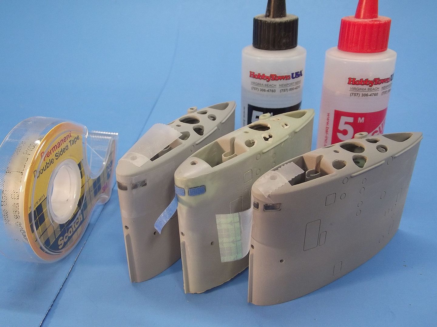


    I’m presenting three BLUEBACK sails here to illustrate the deadlight-from-epoxy-glue method David advocated.
    First step, to the left --enlarge the square holes a bit – the objective is to prevent any raw edges from being observed after the work is done. Then, a mylar type self-adhesive tape was wrapped around the leading edge of the sail (the surface of this type tape is perfectly smooth, producing a reasonably unblemished surface to the eventual epoxy deadlights), covering the three square holes where the deadlights will take shape.

    Second step, center -- mix up some standard, 5-minute epoxy glue and quickly introduce it to the inside leading edge of the sail so as to fill the open deadlight holes. Holding the sail, leading edge down, and slowly rocking it side-to-side to spread the still liquid glue over and into the square holes.

    Third step, center -- pull off the tape and polish the surface of the cured epoxy with #2400 sandpaper followed by a water based polishing compound. Low tack masking tape, cut to the length and width of the deadlights was applied over the epoxy windows – the sail, at that point, ready for painting.

    An unfortunate artifact of the deadlight-from-epoxy method is the unavoidable introduction of air-bubbles as the two parts of the epoxy glue are mixed. But, at these small scales the clear parts with the occasional air-bubble entrapped in the epoxy gives a ‘busy’ look to what’s supposedly going on behind the deadlights (yes, a convenient rational to an undesirable occurrence, but … what the hey!).
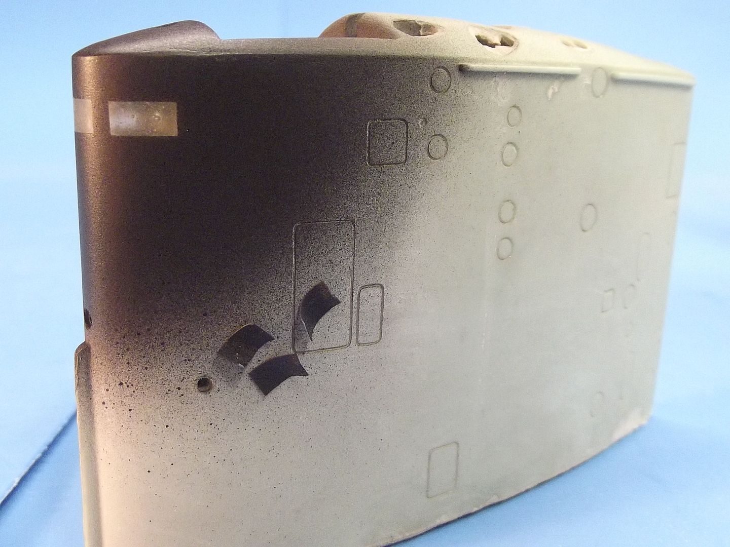


    As the epoxy glazing is a bit wider and taller than scale, and the deadlight mask a bit smaller in dimensions, the possibility of observing the resin edges of the glazed holes is eliminated. As demonstrated in this close-up of the epoxy deadlights once the masking is removed.

    Before laying down any paint I insured that all dings and flaws at the sails leading edge on or near the edges of the polished deadlight glazing was puttied, primed and sanded smooth. After the deadlight masking was in place I had to avoid putty or primer on or near the edges of the masking, as the colors of those agents would become visible once the masking is removed after all painting is completed. And, for that reason, only the final color (a very, very dark gray for this model) around the clear parts substitutes for primer.
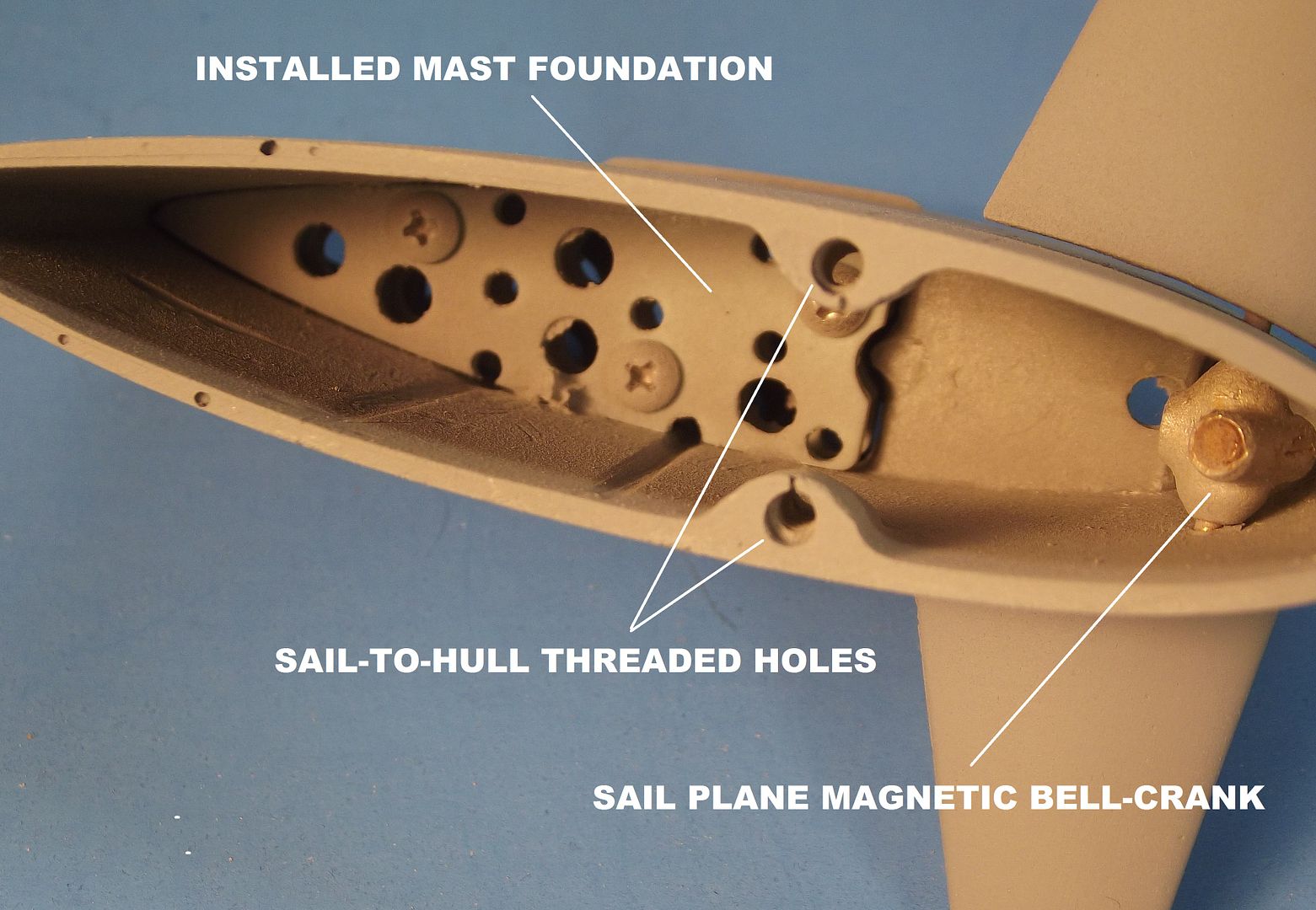


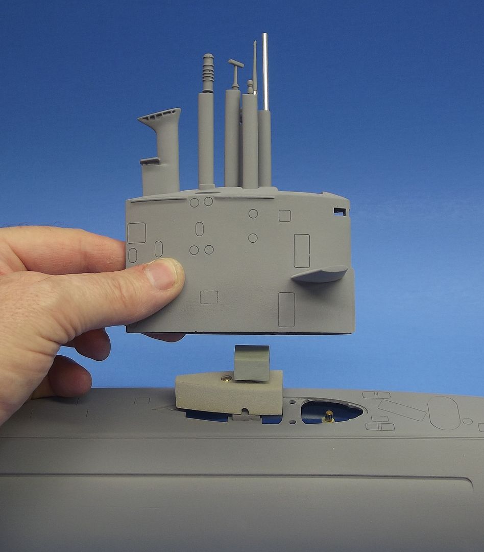
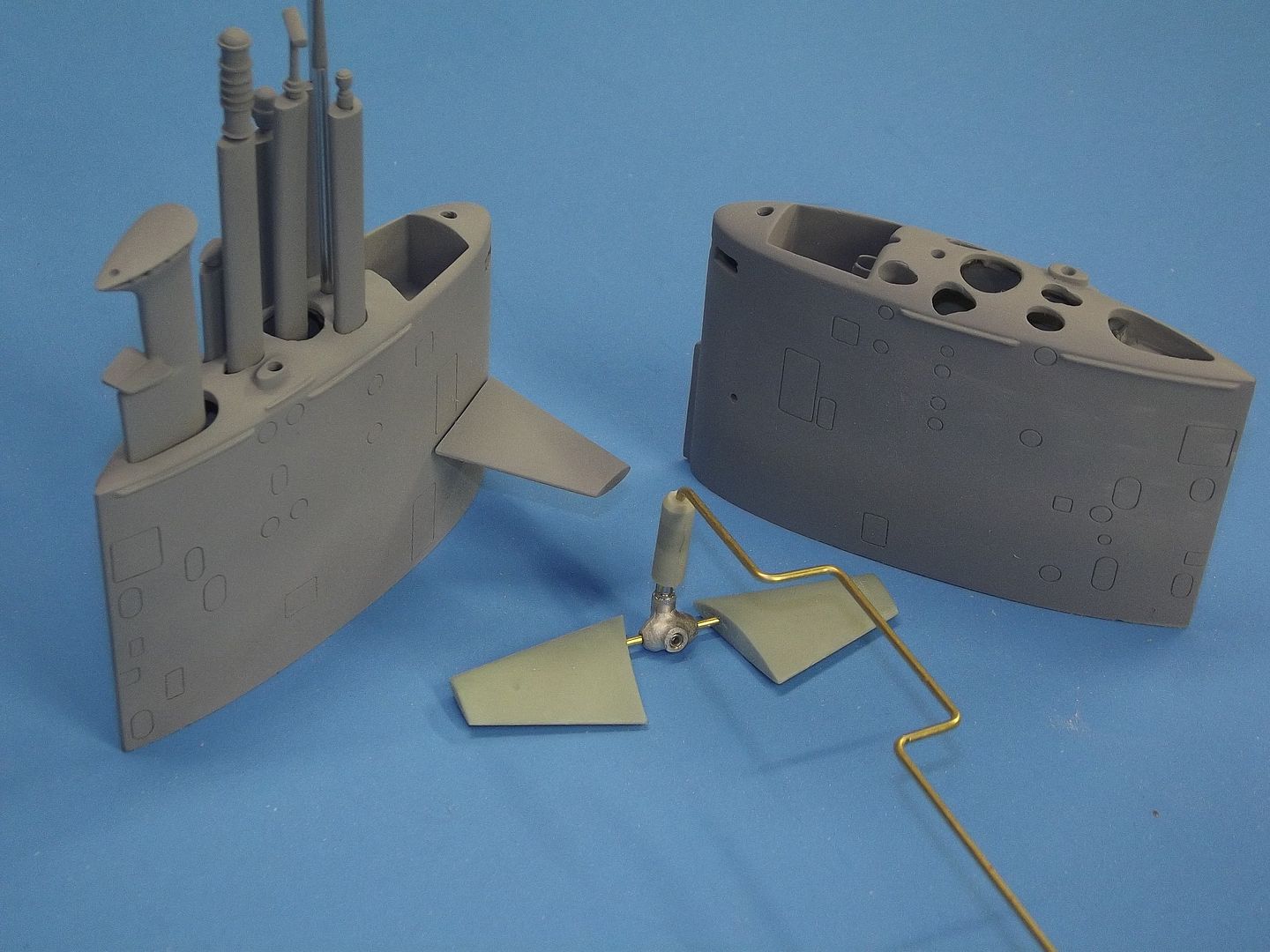
    There are three things going on within the sail. First is the mast foundation: this two-platform structure insures that the bases of the masts are held securely atop the sail, and are also in perfect alignment with one another.

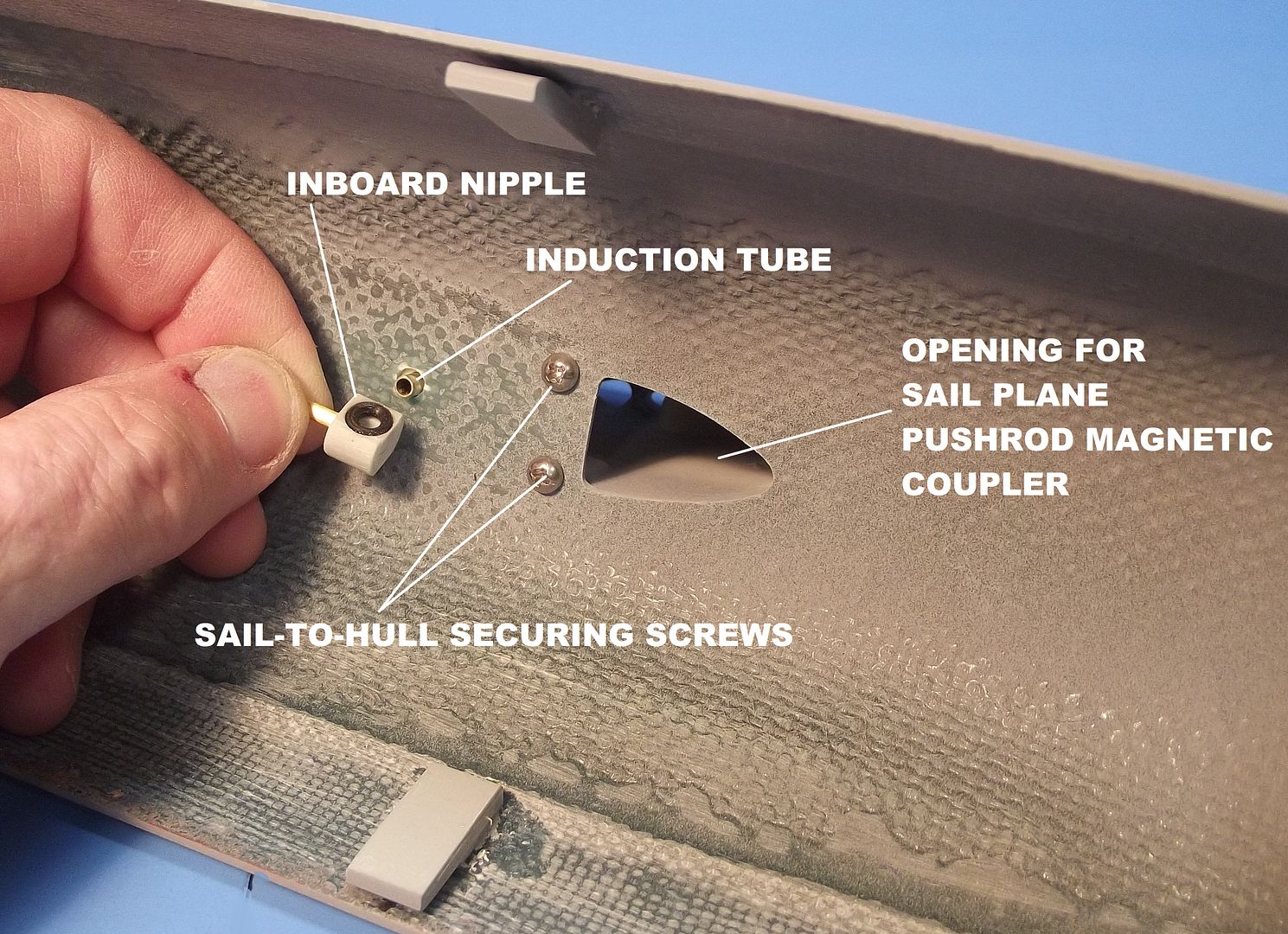
    The second item are the two threaded foundations at the base of the sail. These receive 4-40 machine screws that run up from holes within the top of the upper hull and pull the sail structure down tight into the slight trough built into the hull to nest the sail piece. And finally, the magnetic bell-crank made up to the sail plane operating shaft. The magnet replaces an otherwise awkward and space taking push-rod clevis. With magnets, it’s an automatic make/break proposition with little if any back-lash. Nothing could be simpler.
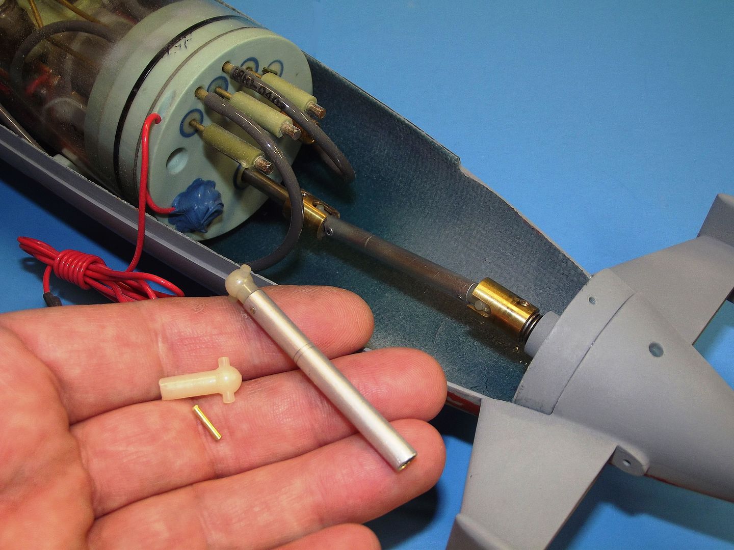


    Unfortunately, the angular off-set of the intermediate drive shaft was found to be rather extreme, necessitated by the very low gear reduction output shaft of the standard 2.5” SD. Though the Dumas type universals at each end of the intermediate drive shaft permitted a sizable fraction of torque to go to the propeller shaft, the noise and rattling did suggest that a significant amount of torque was lost to friction at the SD and propeller shaft bearings due to excessive lateral loading. Oh, well. This ain’t a perfect world, and with today’s high capacity batteries, run time will still exceed my attention span.
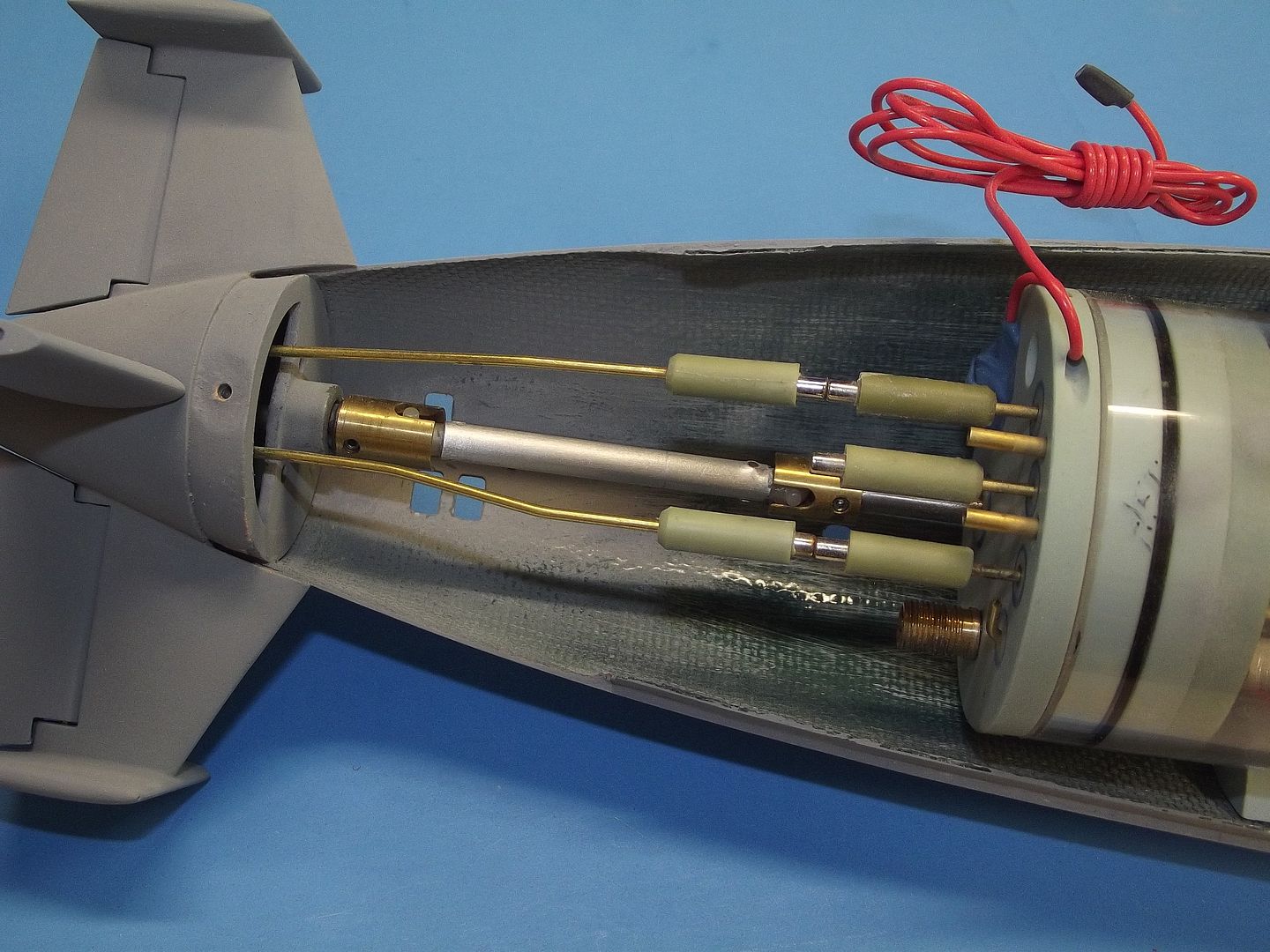


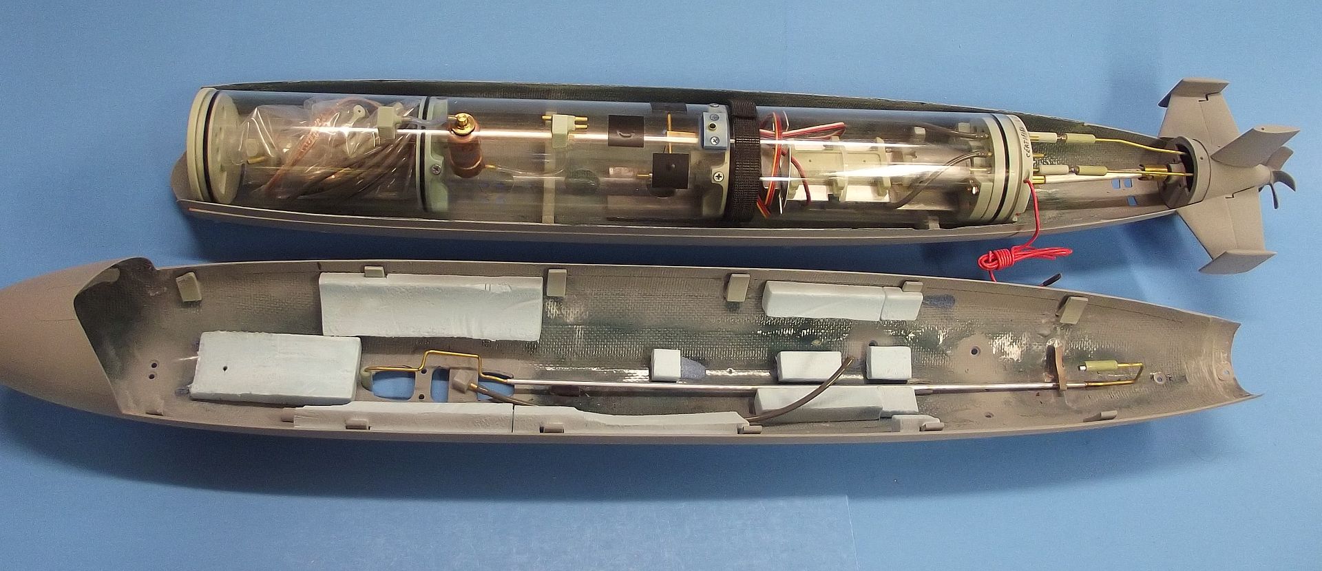
    Use of magnetic couplers keeps the SD-hull interface problem a simple one: Just lower the SD onto its saddles, as I’m doing so I engage the intermediate drive-shaft, then lower the SD till the indexing hole at the bottom of the ballast tank engages the indexing pin of the pin-strap foundation. The Velcro strap is made up holding the SD in place, and the magnetic couplers for the rudders and stern planes made up. The last chore is to run the SD’s receiver antenna down the length of the lower hull (or, if using a 2.4gHz r/c system, running the antenna up the sails snorkel).

    The central magnetic coupler from the SD makes up to the upper hull mounted pushrod which leads to the sail-plane linkage.

    Other than the single machine screw atop the stern, that secures the hull halves together, there are no fasteners that require tools. The magnetic couplers are quick, no fuss, present no back-lash and are what makes it possible to make/break the sail-plane linkage as the hull halves are joined/separated. Today, many r/c model submarine guys employ magnets not only for linkages, but as hull securing devices – I’m the guy who made them popular. However, credit where credit is due: It was Brian Starkes, and excellent and outside-the-box-thinker, who taught me the many uses of magnets.

    Who is John Galt?

    Comment

    • He Who Shall Not Be Named
      Moderator
      • Aug 2008
      • 12309

      #17


      The sail plane linkage is simplicity itself: a cast metal bell-crank girdles the single sail plane operating shaft and makes up to the push-rod with magnets. The kink in the pushrod clears the snorkel mechanisms induction nipple high up within the upper hull. The sail plane operating shaft is permanently CA’ed to one sail-plane.
      Making up the sail-plane operating shaft to the bell-crank goes like this: The bell-crank is held within the sail, and the end of the operating shaft is pushed in from one side of the sail, through the bell-crank. With the root of the sail-plane standing off of the sails surface by about 1/16-inch, and the bell-crank set-screw is tightened. The opposing sail plane is slipped onto the other side of the sail (a tight, interference fit). The ends of the bell-crank just touch the walls of the sails interior, so the operating shaft cannot move longitudinally, i.e. the planes keep their set distance from the hull – no rubbing between planes and sails surface as the planes go through their range of motion.


      Here’s a look at the completed sail-plane pushrod set high up into the upper hull. The 1/16-inch diameter brass pushrod ends are easily bent and fit the magnet couplers. But, the majority of the pushrod is a length of 3/32” diameter aluminum tube – which is not only light of weight, but much more ridged than if a continuous length of brass rod were employed. Two short lengths of heat-shrink tubing, slit along their lengths, glued within the upper hull, hold the pushrod up against the inside of the upper hull. A RenShape ‘finger’ projects over the pushrod – when the two hull halves are pulled apart, the magnetic attraction between SD and sail-plane pushrod magnetic couplers is strong and the finger acts to hold the rod from bowing down as the magnetic bond is broken. Other than that, the finger makes no contact with the pushrod.

      Note the hunks of buoyant, closed-cell foam up high in the model. The foam not only counteracts the weight of the fixed ballast low in the hull. The foam amount and position also works to place the collective buoyant forces (the c.b.) directly above, and well distanced from the center of gravity. It’s desirable for the model submarine (like the real thing) to be statically stable with zero roll, and zero pitch angle when at rest, and to be able to correct itself to those positions after being upset.


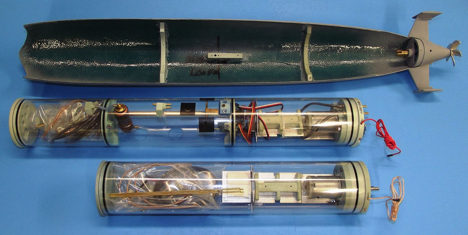
      As with any other free-flooding type model submarine hull the option exists of either employing a system that has a ballast tank (static diving type) or one that does not (dynamic diving type). The upper SubDriver (SD) system is a full-up, ballast tank equipped unit. The SD below, of much simpler design and function, omits entirely the complexity and maintenance burden of a ballast sub-system. Both systems share many features, such as motor-bulkhead, servo mounting foundation, use of a 2.5-inch outside diameter, .125-inch wall clear Lexan cylinder, and forward bulkhead.

      The configuration of the model when using the dynamic type SD is omission of the indexing pin and provision of back-stops to prevent longitudinal movement of the SD; and adjustment of the amount and location of floatation foam within the hull to achieve submerged trim, with the boat only positive enough to place 1-inch of sail above the surface of the water when at rest.

      However, when configured to operate as a static diver the indexing pin is retained – that pin fitting a hole in the bottom of the ballast tank – to secure the SD against longitudinal or radial movement once the Velcro strap is cinched down. I, of course, prefer the more realistic operating submarine, one configured as the static diving type.


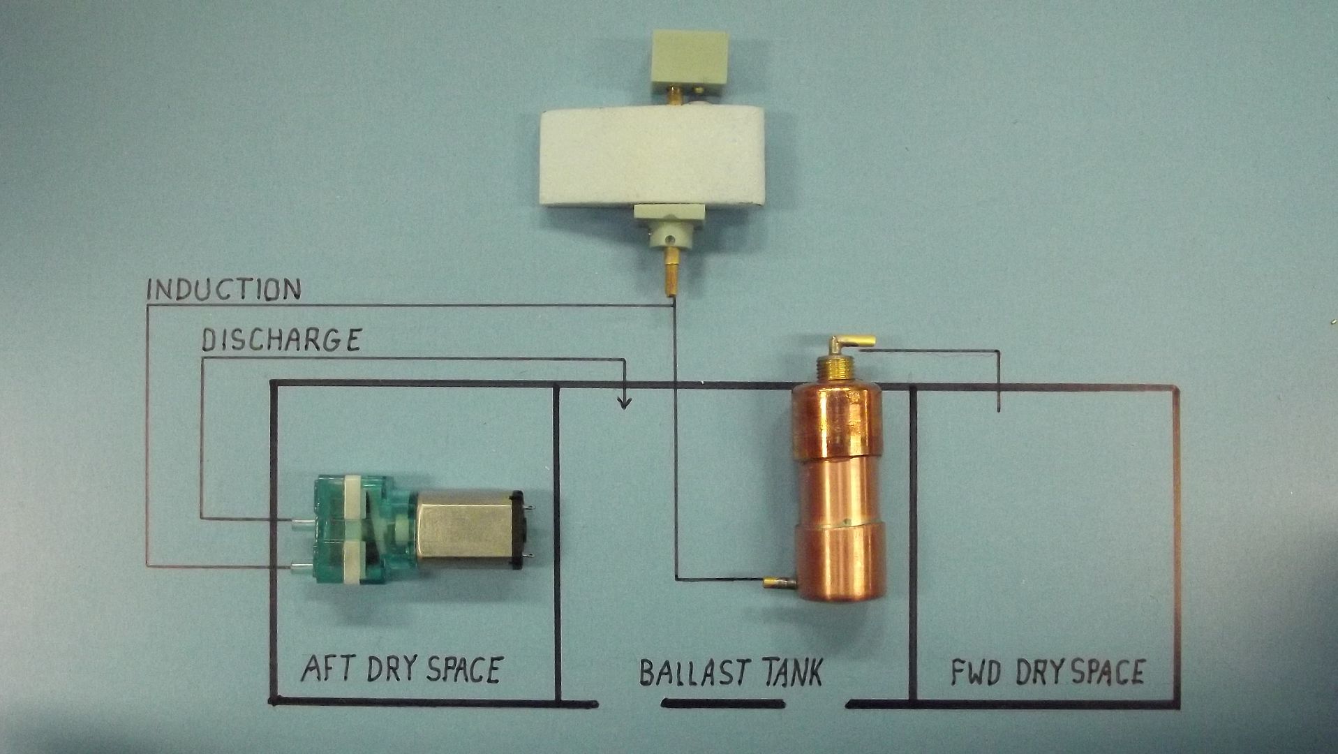
      The static type SD system employs the Semi-ASpirated (SAS) type ballast sub-system, which requires use of an induction snorkel. That snorkel mechanism mounted under the sail, atop the hull. This type SD -- with the ability to take on a weight of ballast water equal to the weight of the displaced water presented by the above waterline portions of the submarine – is a very close analog to how ‘real’ combat submarines work, i.e. blowing air is either gathered from the outside (snorkel) or from an inside source (the SD dry spaces themselves. The surfaced submarine at rest with an empty ballast tank is in a state of neutral buoyancy. The submerged submarine at rest with a full ballast tank is in a state of neutral buoyancy – but it has taken on ballast water weight equal to the weight of the displaced water presented by the above waterline structures.

      There are any number of means of getting ballast water in and out of the statically diving submarine. SAS is but one of many.


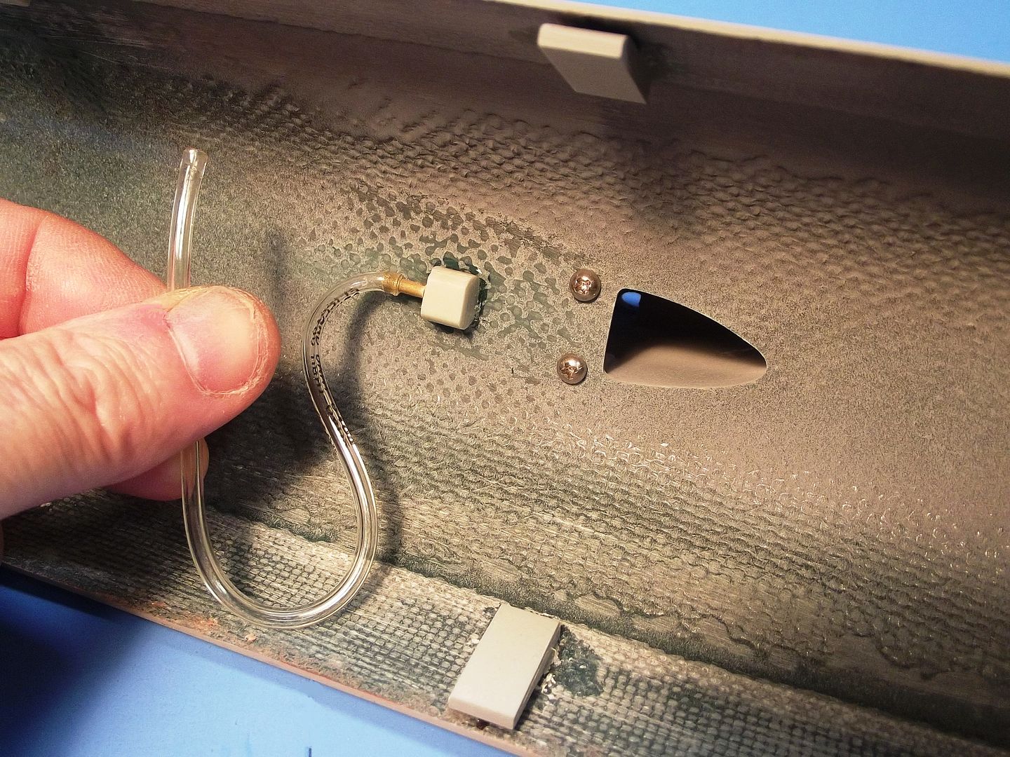
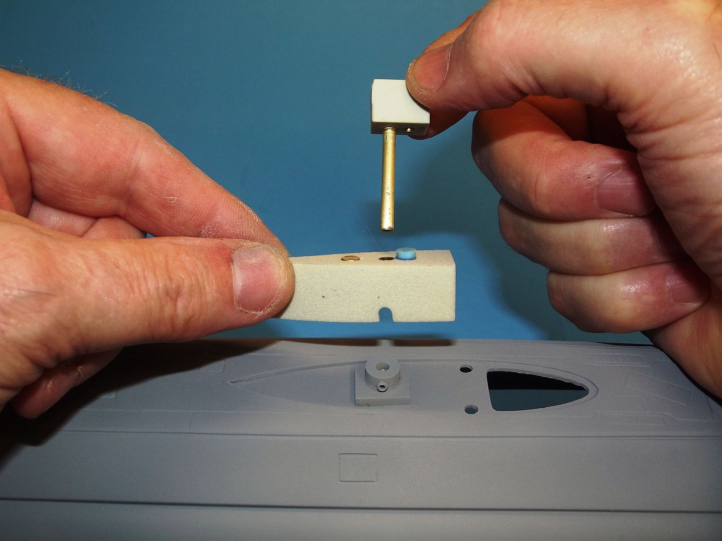
      The inboard nipple is an elbow plumbing fitting that makes up the flexible hose that connects the SD’s low pressure blower (a positive displacement diaphragm type pump) to the snorkel induction tube. When the submarines sail is above water the open snorkel valve permits air to enter the SD dry spaces and low pressure blower.

      The inboard nipple is necessary as there is very little annular space between the SD cylinder and top of the hull. The flexible hose would otherwise kink if not for the elbows horizontal orientation.


      The snorkel mechanism is nothing more than a weighted float with a rubber element atop it; an induction pipe; and the snorkel induction head-valve. The induction pipe is pushed down through its foundation until the bottom of the tube seats within the o-ring atop the induction inboard nipple within the hull.


      The buoyant foam closes the snorkel valve when submerged, forcing the SAS ballast sub-system to draw ballast blow air from within the SD cylinder. When the sail broaches the surface, a weight in the float helps unseat the snorkel head valve, permitting air into the SD, breaking the partial vacuum created during the initial submerged blow. The safety float-valve is a back-up: should the induction line flood (malfunctioning snorkel, or parted flexible hose for example), water pushes a float within the safety float-valve to close off isolate the induction plumbing from the SD’s interior. Two-valve protection is a tenant of the submarine community! Learn it, love it, live it.

      The SAS has many advantages over the other ballast water management schemes:
      No trim changing, and explosion hazards as associated with liquefied gas; no power hungry, high cylinder overpressure, and expensive piston(s); no RCABS wasted space, unpredictable IV bag creeping, and cylinder overpressure; no sloshing water, slow peristaltic pump as used with a pressurized ballast tank; and no reliance on a surfaced vent line for a pumped ballast tank.


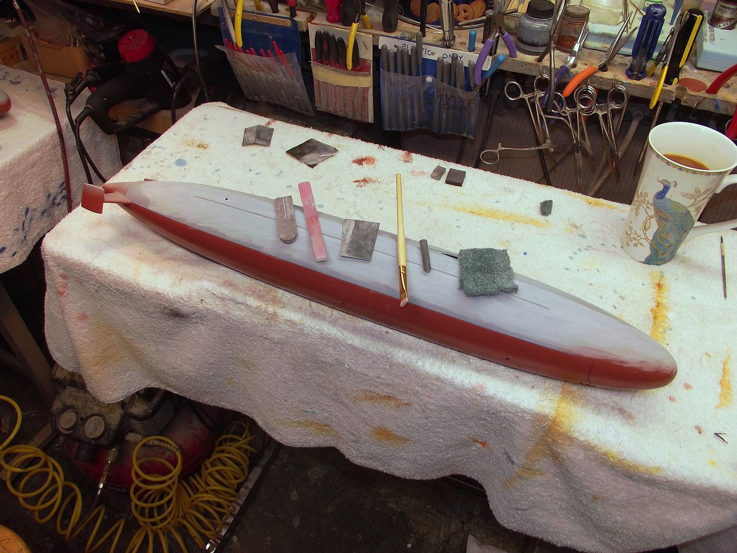
      A good paint-job starts with hours of preparation before the first color goes down. First, the surfaces of the metal, resin, and GRP parts must be prepared for tight adhesion of the primer. All flash, nubs, pits and bumps are filled and abraded away.

      All adhesives, cohesive, putties, fillers and primer selected for their compatibility and sticking power. Such choices based on decades of experiment and practice.

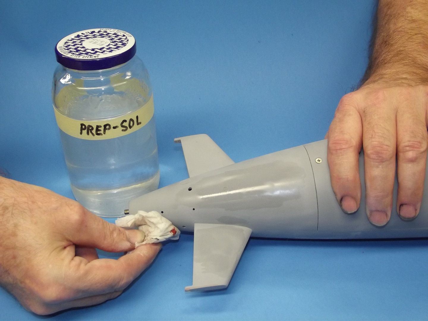
      Even though all parts were brought to an eye-ball perfect finish, the parts were handled and sat around as other work was attended to. So, their surfaces became contaminated with oil and dirt. To ready the parts for the final, thin ‘evening out’ primer coat, they were scrubbed with a special automotive preparatory solvent – I use the one marketed under the DuPont label. A very weak hydrocarbon it’s strong enough to clean the parts, but not so active as to attack the primer.


      Who is John Galt?

      Comment

      • He Who Shall Not Be Named
        Moderator
        • Aug 2008
        • 12309

        #18


        OK. Paint time. Now what? Car paint!

        The only thing the local brick-and-mortar hobby-shop is good for is glue, magazines and bad advice by some know-it-all who doesn’t. There you can plunk down money for paints; primers, clear-coats, and air-dry putties which are formulated to be safe (lawyer proof). Fine for plastic kits not subjected to the elements, but not fine for r/c vehicles operating in harsh environments.
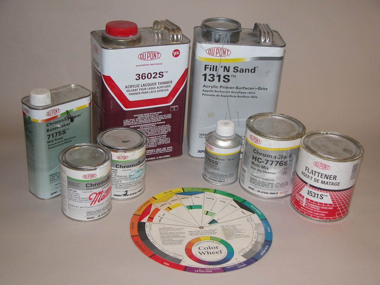
        R/c submarines require durable films that are resistant to UV, abrasion and extreme temperatures (sit a black model submarine on the picnic table in June, and then try to pick it up a few minutes later!). Pass the hobby-shop by and stop in at the local automotive refinishing supply house. For primer I us either fill n’ sand 131S or Nason 421-23 (both pretty much the same thing: an acrylic lacquer based, solvent type coating system, but the Nason is a hell of a lot cheaper). The paints I favor are the two-part polyurethane ChromaColors. The preferred clear-coat is ChromaClear. All these produced by the DuPont Company. Sherwin Williams offers equivalent products if that dealer is convenient to you.

        And learn something about the chemistry and properties of the primer, paint, and clear-coat systems you plan to use. The Interlink is your friend! And test all your fillers, putties, primers, paints, and clear coats on an old discarded model – make your screw-ups on that, not that museum piece you’re currently lavishing all your efforts on.


        The three submarines of the BARBEL class differed from each other. For example, the BARBEL when first launched, had bow planes -- not the familiar sail planes that were added later in her career; and the BLUEBACK had vertical stabilizers at the stern. The BARBEL did not.


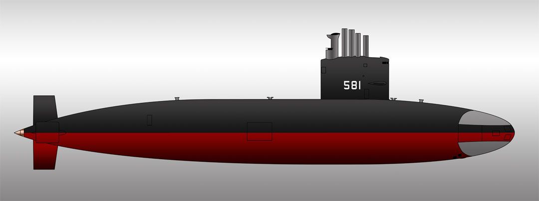
        The paint scheme, which is the important issue here, is typical of most American submarines of the period: black from centerline up, anti-fould red (a brick red color) from centerline down. Other variations in color and markings occurred during the operationl lives of these boats. When initially launched, before commissioning, the boats likely had the anti-foul red from waterline down. Also, during that period, the two escape marker buoys would have been painted international orange. And there were alterations in placement of the rudder and bow draft numbers. And the operational boats seldome displayed their hull numbers on the sail – those present only during launching, pre-commissioning work-up, and award ceremonies.

        I took liberty with scale by showing a ready-for-patrol hull paint scheme with hull numbers on the sail, I also painted the two escape buoy markers ‘international orange’, which was not practice for a boat out on deployment. I made these departures of scale in an effort to make the model submarine easier to see as it operated underwater.


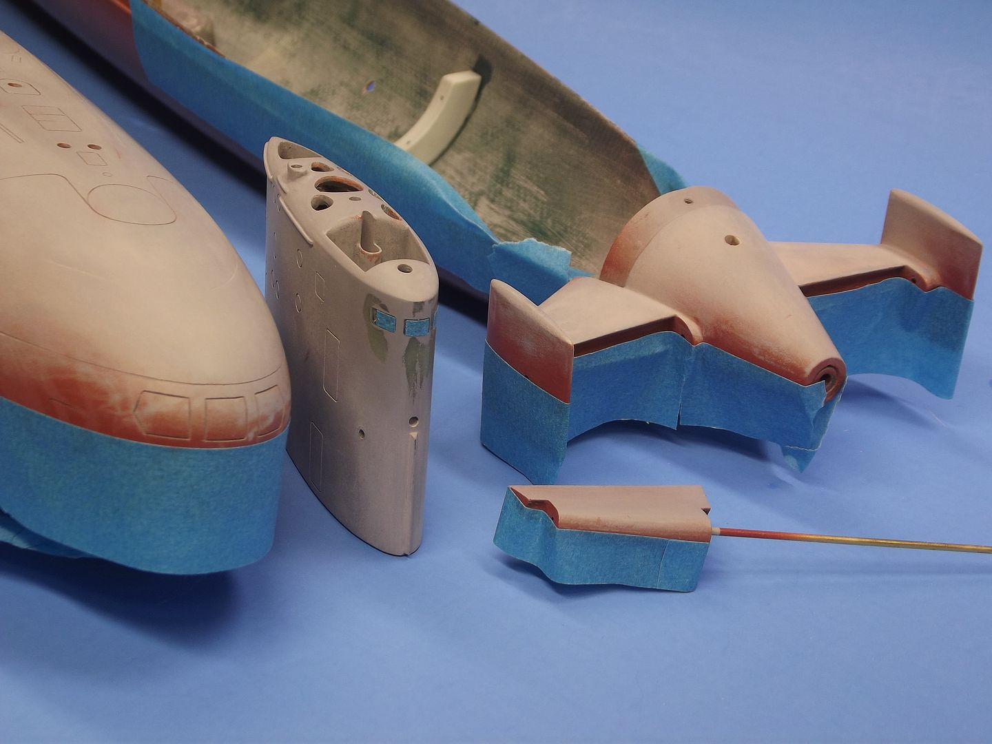
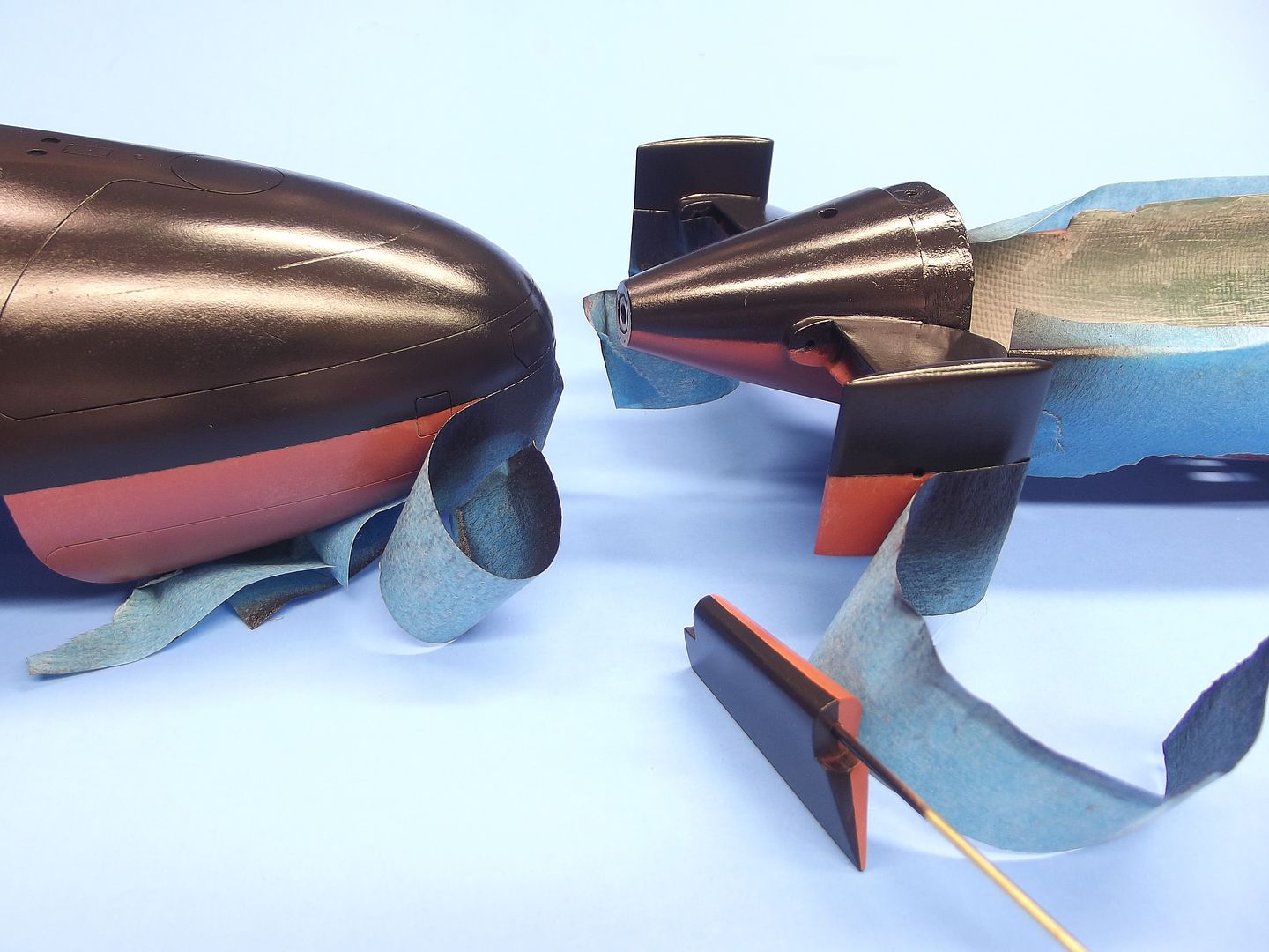
        Painting the red was an easy mater, as the demarcation line between the red and the eventual ‘black’ falls along the plane where the upper and lower hull separate. So, with the two halves separated, I paint the lower bow of the upper hull red, and the entire lower hull (with attached tail-cone) red. Also painted red were the lower rudder, and bottom of the stern planes.

        A virtue of the two-part, exothermic curing polyurethane car-paint is its quick transition from wet- to- tack-to-hard cycle – this is professional paint, formulated for quick-dry and durability. This is quality car paint, not some crap of unknown quality and chemistry squirted out of a rattle-can.


        Once the red had cured hard I masked the red-black demarcation line with low-tack tape in preparation of laying down the black. But, to be correct, not black. Rather a dark, dark gray.

        For two reasons: Scale effect – the apparent lightening of a color with distance (due to atmospheric attenuation of the reflected light between subject and observer). And the normal bleaching of paint as a result of UV induced changes to the paints pigments and carrier and oxidation.

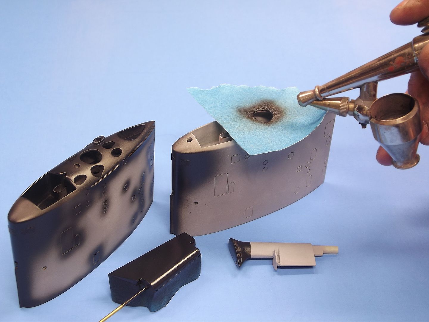
        Note the masking over the three deadlights atop the leading edge of the sail.


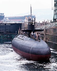
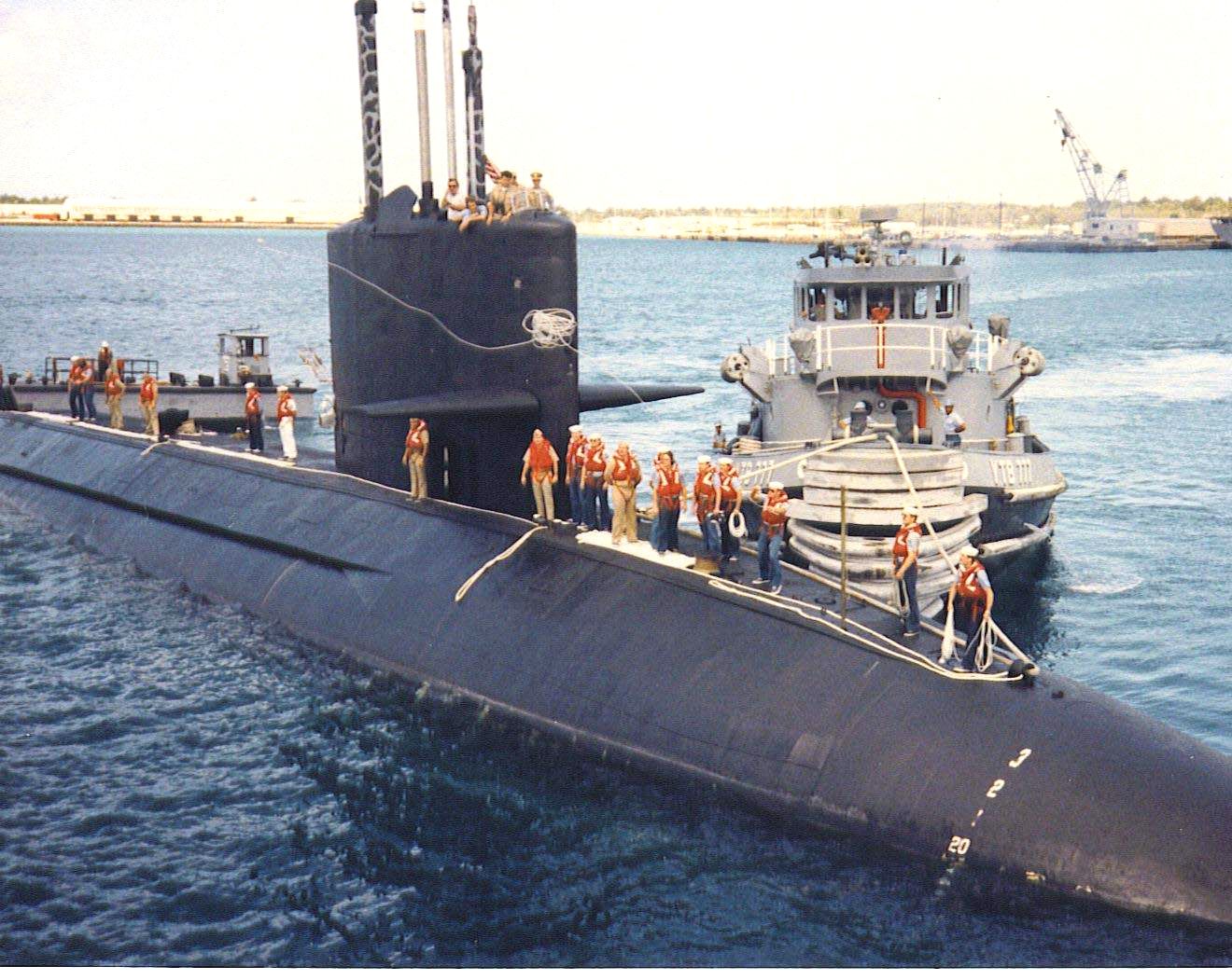
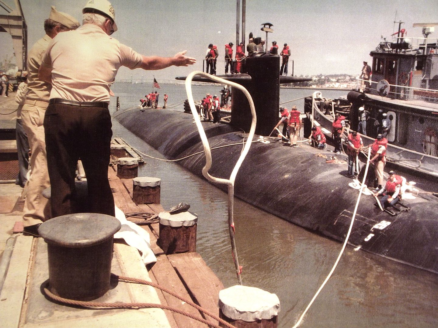
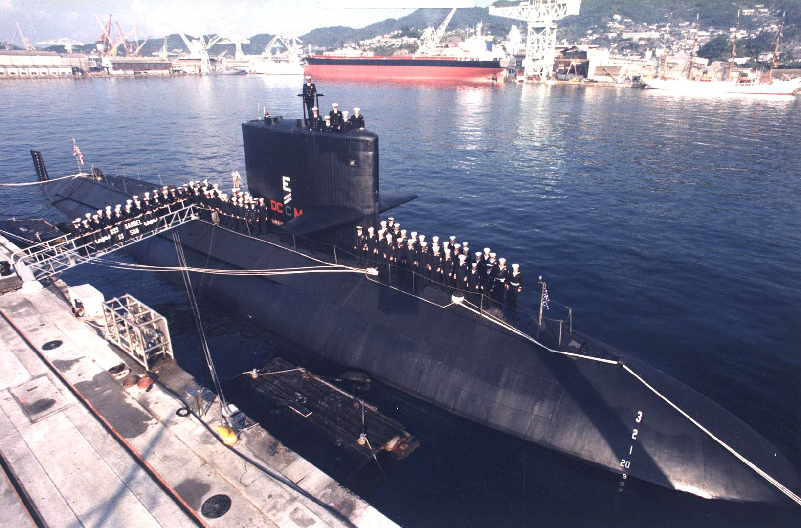
        The slight bleaching any paint system undergoes with prolonged exposure to the elements; and foot traffic, bird-poop, and chemicals spilled over the vehicles structure well illustrated by this shot of one of the BARBEL class boats. Black is the topside ‘color’ an American combatant starts life with … but it soon becomes something other than black till the next paint-job.

        An operational boat does not display name or hull-numbers. Also note that the surface of the escape buoy markers is also the same ‘black’ as the other topside elements of the boat. Only markings are the draft numbers at the bow and upper rudder.


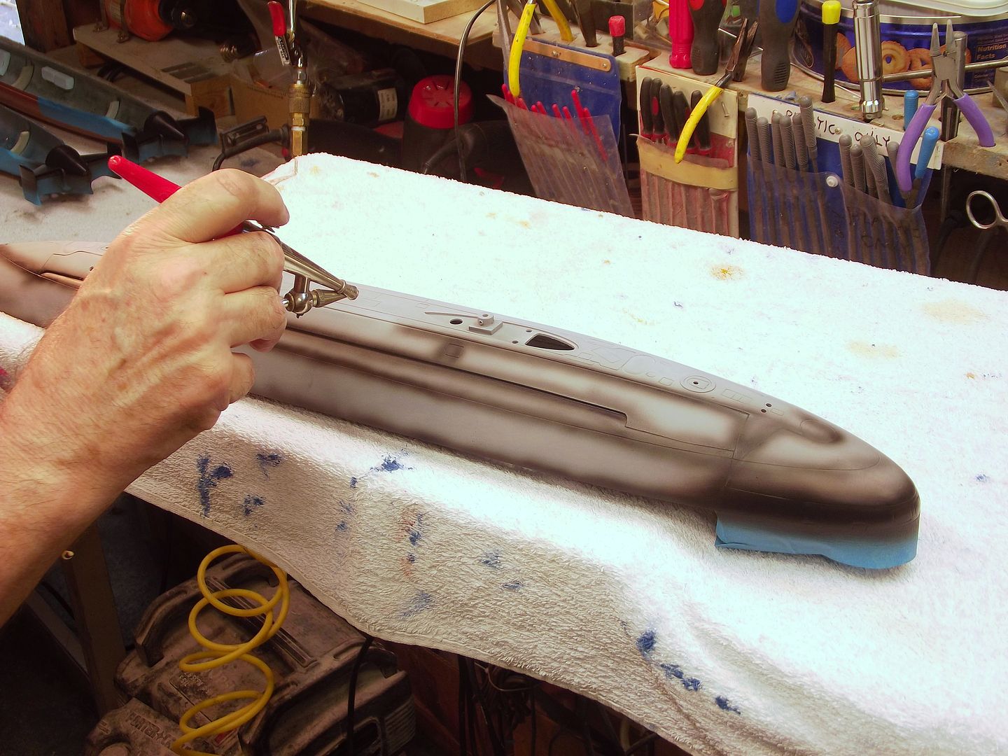
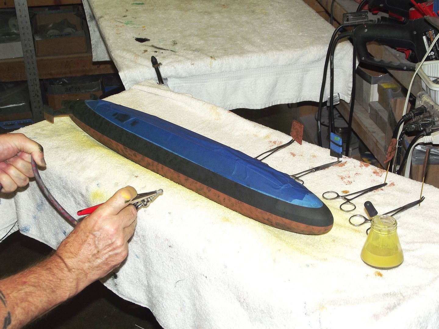
        Cutting in the black to the hull. Here I’m using my nasty, old Paacshe Model-H single-action spray-brush to apply the dark, dark gray to the hard-to-get-at portions of the model parts. Don’t confuse this cutting in step with ‘pre-shading’. Once the hard-to-get-paint-at cutting in was done I cranked up the air pressure, pulled the metering needle all the way back and blasted the model with the dark, dark gray.

        I HATE PRE-SHADDING!!!! Did you ever see a vehicle with such gross off-color shading between structural and access plate seams and weld beads!???..... Why paint a model like that? I hate that ****!


        To keep from getting too much black paint atop the sail, I temporarily applied masks to its surface as I shot paint into the area seen through the open mast faring penetrations. Most of the time the model will be displayed with all masts in place, but when at the lake I’ll only have the #1 or #2 scope up there, the other masts and antennas left nice and safe in the field-box. That leaves a lot of open holes atop the sail – I don’t want anyone peeking in there and not seeing black.


        Black was applied to the upper rudder, sail, sail planes, top of the stern planes, snorkel induction head, and upper hull. That work accomplished with a bit higher air-pressure, a closer tip-to-work distance, and slower strokes. The objective is to put the paint down wet – almost to the point of running.

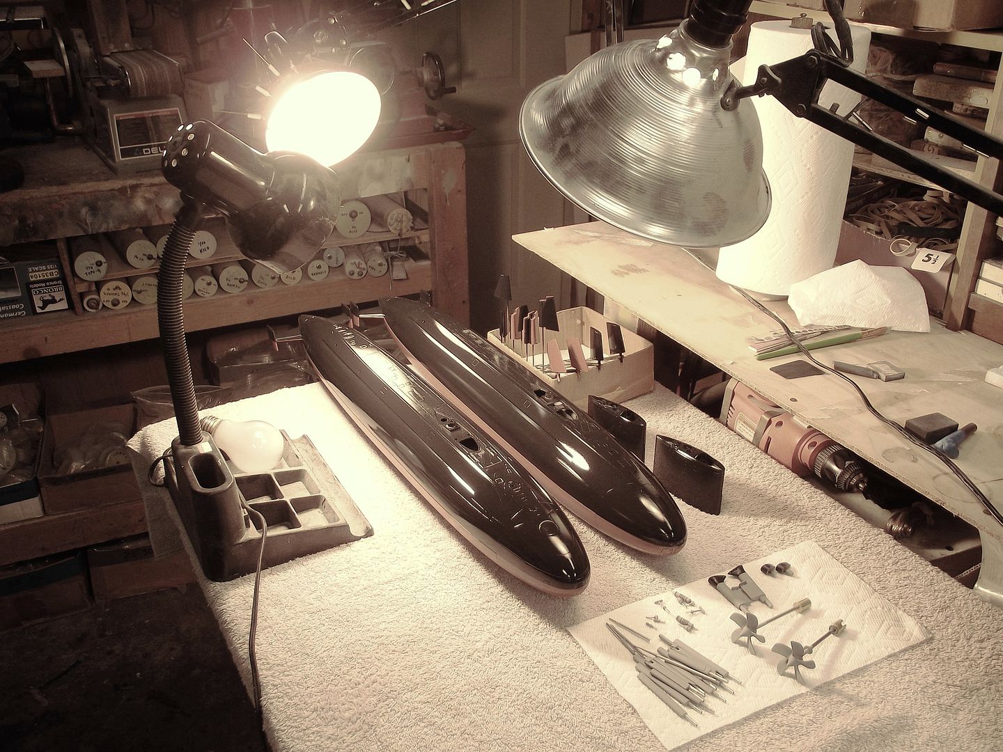
        Though the two-part polyurethane paint cures quickly, I’m the impatient sort, so accelerate the hardening process with some 100-Watt incandescent bulbs (remember those, you Obama fans?) distanced enough to not get the work too hot, but hot enough to get the work ready to mask in a few hours time. Try THAT with a rattle-can paint!
        Who is John Galt?

        Comment

        • He Who Shall Not Be Named
          Moderator
          • Aug 2008
          • 12309

          #19


          With the basic colors down – anti-fouling red and dark, dark gray – all painted surfaces were given a moderate coat of clear-coat to protect the underlying paint from damage should I have to abrade off some weathering during the later finishing operations.

          An excellent paint job is the canvas for the final steps: weathering, markings, and clear-coat, the agents when skillfully applied give the appearance the look of, ‘real’.


          Weathering: the process of using different types of mediums and application tools to render a ‘used’ look to the model. Without weathering the model, no matter how well assembled and painted, will simply look like a flawless toy. But, weather that toy well and it transforms from well crafted model to a display that credibly represents the ‘real thing’!

          Our environment contains gasses, particulates and liquids that affect the submarine mechanically as well as chemically – the pounding of waves over time will dish in light metal plating between frames and stringers; marine life in its many forms will cling to the below waterline portions of the hull and produce all sorts of colors textures, and strata; birds will unashamedly **** over everything, and those portions of topside structure sailors can’t get at quickly (the top of the upper rudder for examples) become stained with running bird-****; and any number of liquids spilled on the deck (milk, eggs, hydraulic fluid, diesel lubricating and propulsion oil, paints, thinners, cooking oils, etc.) and mineral laden sea-spray will accumulate topside and run, with rain-water, as streaks down the sides of the sail, hull and upper rudder.


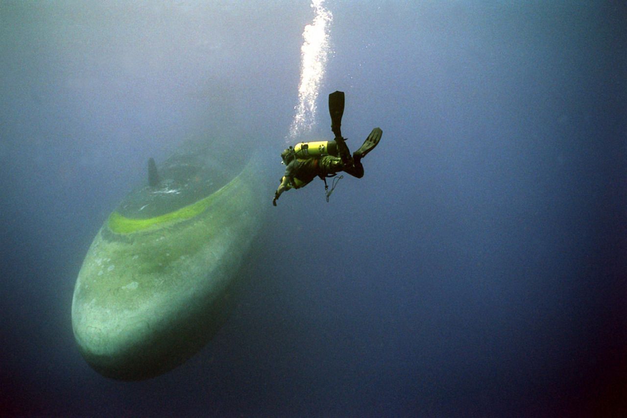
          The look of marine growth on the below waterline portions of the submarine in the water and out of the water are two different things. Even accounting for the loss of some red in this shot, you can still make out the rich color and splotching patterns on this submerged submarine (likely running the range in the Bahamas – a damned good billet for Navy Divers). Once a boat is hoisted out of the water in drydock this marine growth dies and quickly bleaches out to a tan-brown, stinking muck.

          So, a decision has to be made: do I want a model representing an in-water boat, or one that’s been in drydock more than a day? I prefer the in-water look, and that’s how I represented the underwater portions of my SWM 1/96 BLUEBACK model.


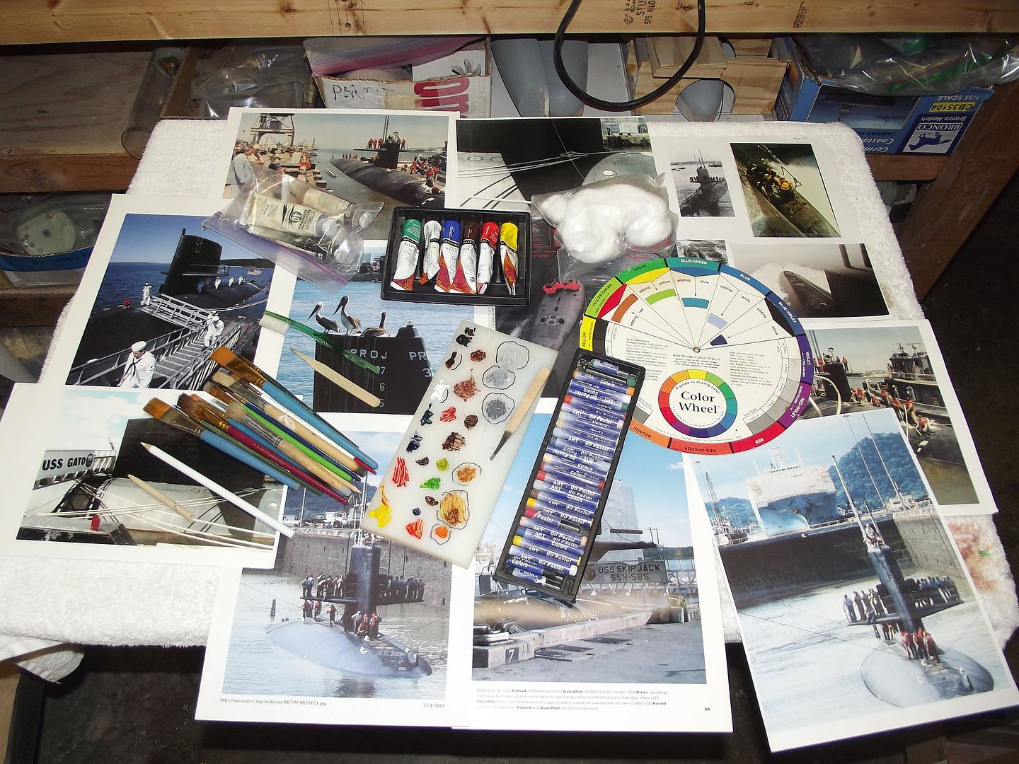
          Weathering is an aquired craft. You’re not born with it, It’s not something you get out of a box, it’s a skill learned by gathering relavant documentation and then just ‘doing it’.

          Weathering is the broad term applied to inviromental and operational changes in appearance as the result of use over time. This change in appearance is simulated through use of any number of mediums and tools of application. Of course, extensive study of prototypes is required to determine the color, steak, and smear patterns typical for the type vehicle being represented in model form.


          Unfortunatly I failed to take any pictures of the topside weathering process on this model. So, a word discription will have to sufice. Gravity and the shadows the sun throws on dished-in sail and rudder plating are the things captured on the above waterline portions of the model. Gravity directs the flow of rain-water at it caries the dirt, oils, and other contamination solids and liquids that gather on the sides of the sail, rudder and hull. Sunlight throws shadows on partially sunken portions of sail and rudder plating, the light and dark areas created form a chekcer-board pattern seen on any boat that has been at sea for a significant amount of time. The dishing is not because of water pressure (discounting that seen on the bottomed SCORPIAN’s appendages – that’s an atypical situation), it’s a consiquence of welding heat distortion and wave action against the plating in heavy seas.


          The ‘581’ and draft numbers are commercially available dry-transfers. Soon after they were applied, a clear-coat was sprayed over them to protect them from handling damage, also to provide a consistent surface over which the weathering agents would be applied and worked.

          The hull numbers went down only after the checker-board plate dishing had been applied and toned down with the base dark, dark grey. In weathering, ‘less is more’ is the watch-word.


          Rain water runs along a structure and picks up contaminates as it runs down the sides. When you smear a weathering agent think only one thing: where will gravity pull this running water? That’s all there is to streaking on the sail, rudder and hull. Note the running rust and lighter colored streaks representing typical grime and oils dragged down by rain water.

          The checker-board dishing pattern to the sail and upper rudder was achieved with hoizontal and vertical strips of tape (the width of the strips equal to the frame and stringer spacing on the prototype) applied and a pure black lightly sprayed into each sunward corner of a masked off square. You can just make out the checkerboard pattern on the sail. The dishing is done before any markings or weathering operations. A mist coating of the dark,dark gray over the dishing work is required to tone-down the work – I wanted the viewer to get just a suggestion of dishing, not to be overwhelmed by the effect.

          Once done with the above waterline weathering and markings, all those surfaces were given a clear-coat to protect the work from handeling as I worked the below waterline portions of hull and lower rudder.


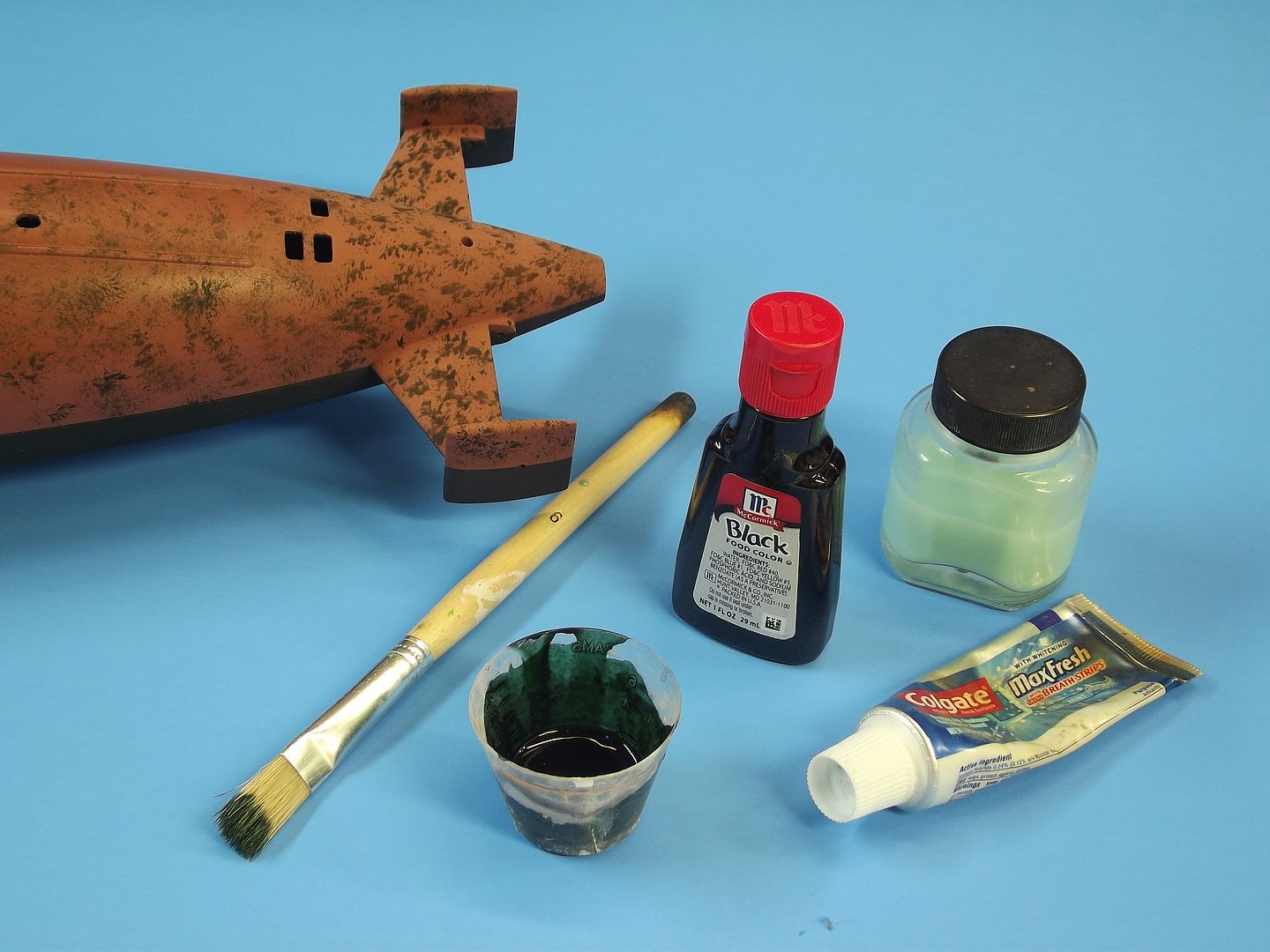
          Water thinned tooth-paste (in the glass bottle) makes an excellent water soluble painting mask. By adding food-coloring to the mix I can see where I’ve applied the masking. The masking ingredients and tool (a very stiff horse-hair brush) presented here.

          The above waterline portions of the hull and stern planes were masked off with tape, and all below waterline items (lower ruder, bottom of the stern planes and lower hull) stippled with the tooth-paste mask. First step in representing the uneven distribution of marine growth on the submarine, but is also an ideal medium to mask when simulating chipped paint effects.


          Look at any dry dock photo of s ship up on the keel-blocks. Examine the below waterline areas and the first thing you note is the splotched, uneven and patchy differences in color of the dead and dying marine growth that invariably clings to most man-made object that has been exposed to water for any length of time.

          The above waterline areas of the hull were masked off with low tack masking tape, as was the above waterline portions of the upper rudder. I then stippled on the tooth-paste masking medium to all below waterline portions of the model. A semi-opaque (paint cut with clear) very light tan color is mixed up and misted to all below waterline structures. After that first light coat of paint dried I wiped all parts down with a very damp dish-towel to scrub away the tooth-paste masking. This presented a rather stark splotchy appearance with was toned down with another light spray coating of the yellow-tan paint

          Who is John Galt?

          Comment

          • He Who Shall Not Be Named
            Moderator
            • Aug 2008
            • 12309

            #20


            The above shot shows the splotchy marine-growth – multiple shots of marine-growth with tooth-paste stippled masking between the coats. Before the last marine-growth coat I brushed a wide strip of tooth-paste mask from water line down. Most real boats evidence a stratification of growth between water line and a few feet below it, with an almost white line at waterline (dead marine growth that bleaches out). That ragged white line at waterline done with an ‘artist’ pencil.


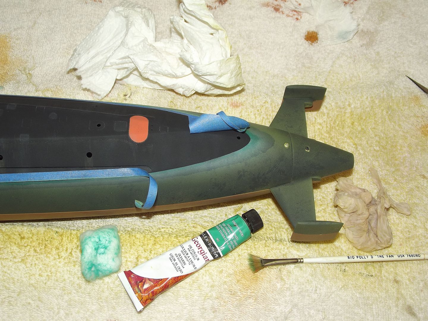
            Below waterline weathering was topped as I rubbed a very small amount of green oil-paint from the edge of the masking tape down, blending the green in with the base and marine-growth colors. The oil was dabbed on with a fan brush and pulled into the work – down strokes only!) using a tightly packed cotton ball.

            The last below waterline job was done after all the masking was pulled away, an ‘artist’ white color pencil was used to lightly lay down a ragged line at the waterline. This was pulled down a bit with fingers and cotton balls. At that point all below waterline portions were give a heavy coat of flattened clear-coat to protect the work.


            Typically, on diesel-electric submarines, the engine exhaust plumbing is injected with sea- water to keep things from over-heating and to abate some of the noise. The water mixes with the particulates of the exhaust and accumulates as a salt and soot laden streaking down the sides of the hull.
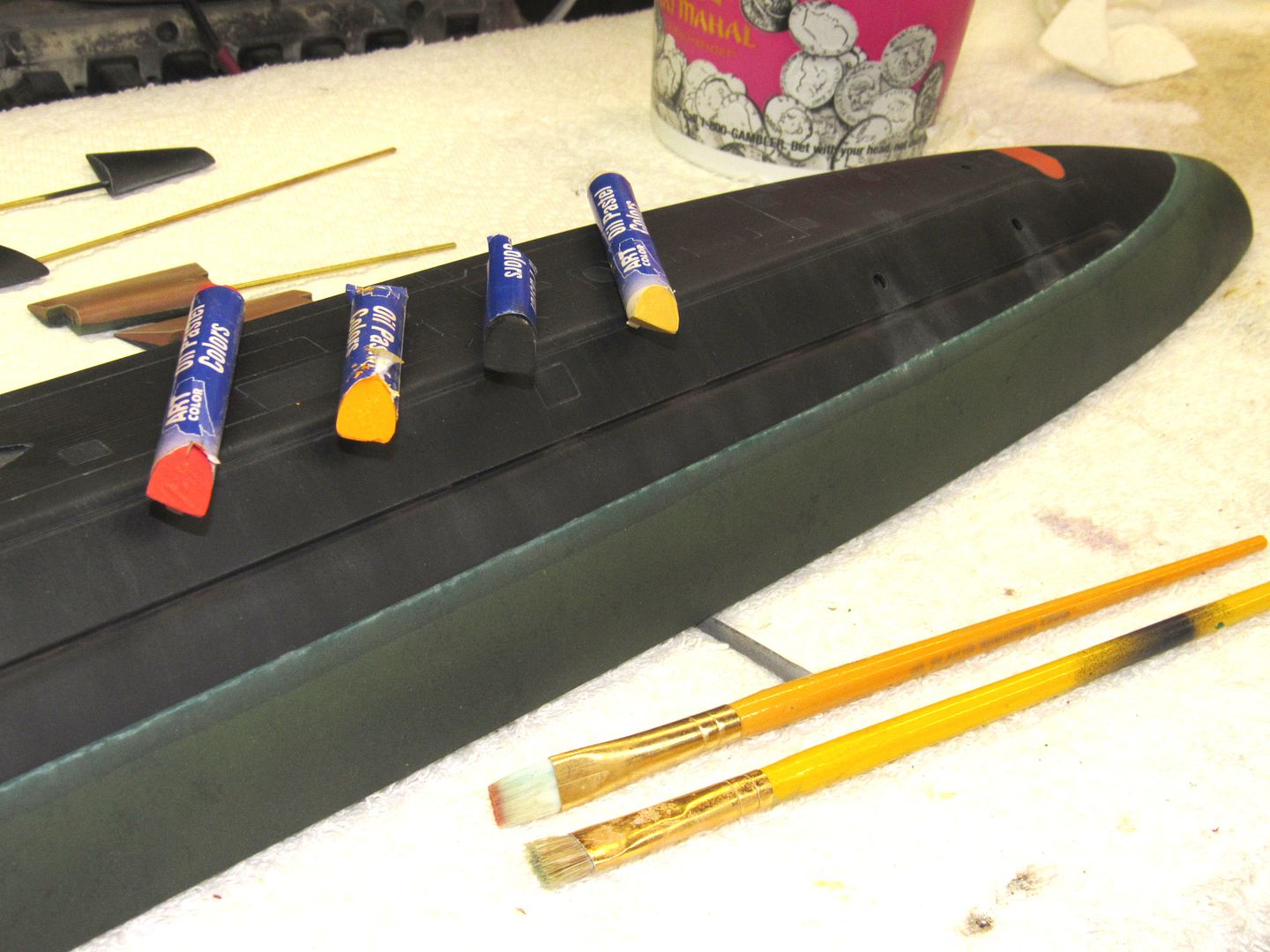
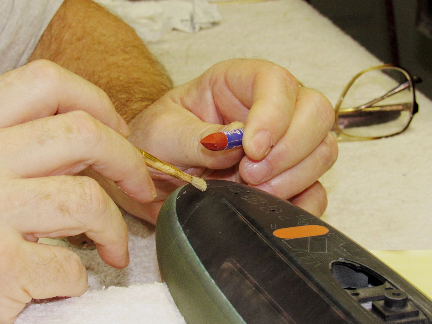
            Oil based crayons were used for rust and carbon soot effects. This material is much, much softer than wax crayons (the type a kid would eat when the teacher’s not looking). When applied its texture is a bit like lip-stick, but quickly turns to a thick liquid as it’s rubbed into the work. Here I’m using a light-gray oil based crayon to start the running soot seen from diesel exhaust ports.


            Most of the running rust on the sides of the superstructure was done with the ‘artist’ crayons. A dab of color was applied to the model right from the crayon, then smeared and pulled down with a stiff brush. You can see the rust effect at the longitudinal superstructure break and safety track near the deck.
            These crayons have pretty much replaced the ‘artist’ oil paints I had been using for streak type weathering effects in that I have more control as to the amount I can apply and push around with brush and other tools.


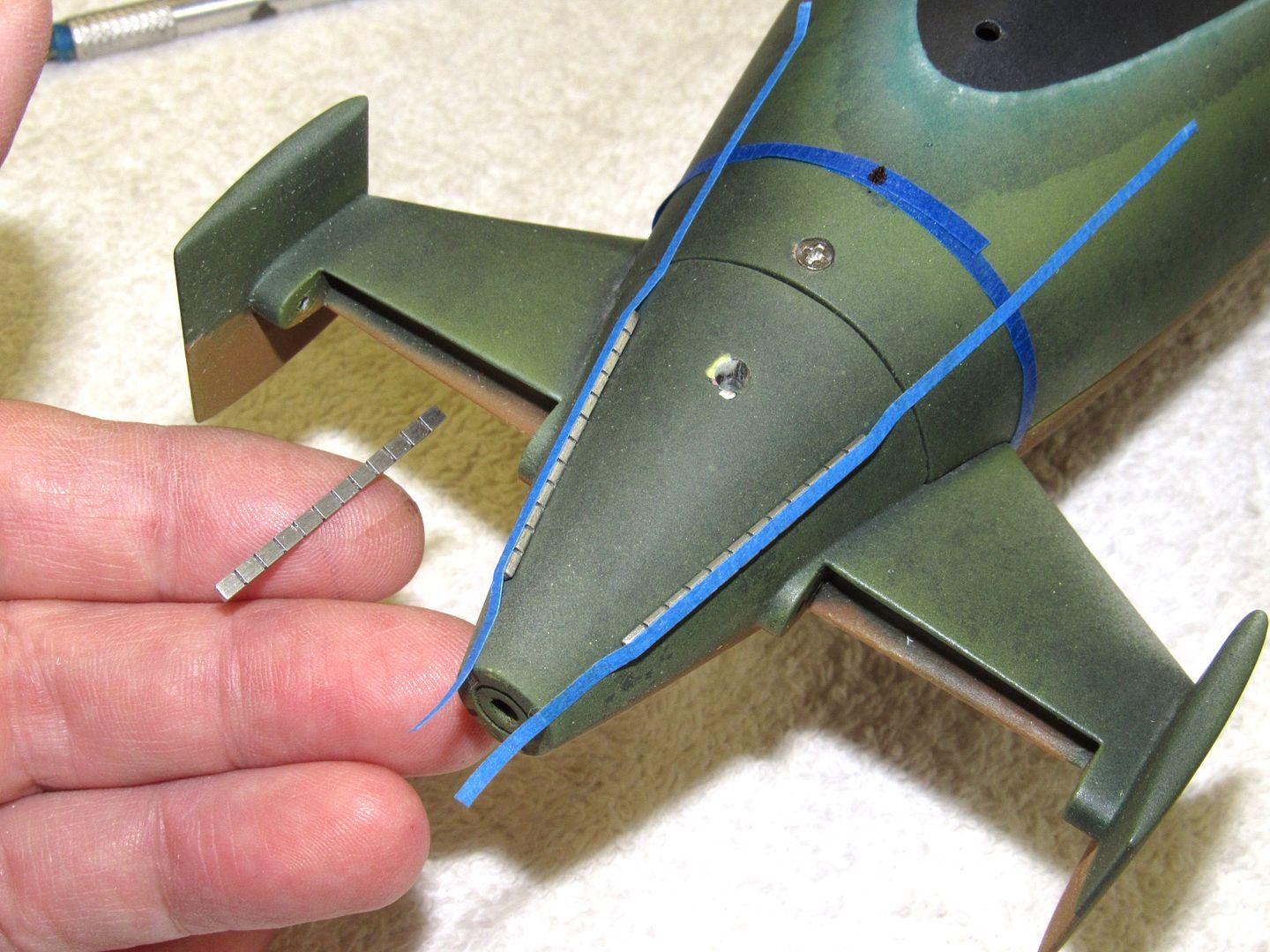
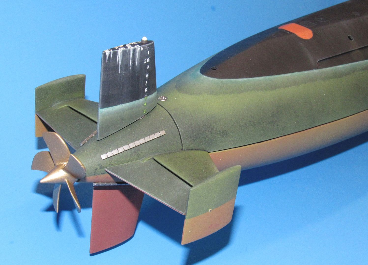
            Four rows of zinc anodes were represented by polished white-metal parts. The trick was to CA them to the stern, centered and with the minimum of glue-smear. I first wrapped a radial strip of tape forward of the horizontal stabilizers and marked on the tape the four points that would place the line of each row of zincs to that point. Each row of zincs was secured to a strip of masking tape and each row test fit to the stern to check for symmetry between them as well as correct position on the hull. Once happy with the look of things, each row was lifted from the front (still attached to the stern by the tape), glue applied, and the row of zincs carefully laid down and held there till the CA had cured hard enough for the tape to be removed.


            Dry brushing … admittedly over-done here … is the practice of applying an oil based paint to the edges of a models upper surface to render the effect of sunlight glinting off those surfaces. As you can see I went way overboard at the tips of the sail planes and horizontal strakes near the top of the sail. I did a better job of it at the soft edges between main deck and sides of the superstructure – you can hardly make it out, but the edges were highlighted just enough to suggest the transition from flat to slopping surface.

            You take the paint from the tube, put it on a pallet and pick it up with a soft ‘fan’ brush. Before going to work the majority of the paint is pulled out of the brush with a rag and repeated stroking on a cardboard box. So little paint is left in the brush so that only repeated swipes of the brush at the models edges will deposit a bit of white. Dry-brushing makes things in high relief pop out as a wash will accentuate sunken details.


            Who is John Galt?

            Comment

            • trout
              Admiral
              • Jul 2011
              • 3547

              #21
              I know taking photos, editing them, creating dialogue, all take a lot of effort and time. Thank you for doing this!
              If you can cut, drill, saw, hit things and swear a lot, you're well on the way to building a working model sub.

              Comment

              • Scott T
                Commander
                • May 2009
                • 378

                #22
                Thanks Dave!

                Comment

                • RCSubGuy
                  Welcome to my underwater realm!
                  • Aug 2009
                  • 1777

                  #23
                  Holy heck.. That was epic!

                  Comment

                  • He Who Shall Not Be Named
                    Moderator
                    • Aug 2008
                    • 12309

                    #24
                    Originally posted by SubHuman
                    Holy heck.. That was epic!
                    Thanks troops. Yeah, my next novel will be Gone With The Wind. Oh ... wait! Some hack already took that title. ****! I wanted to get the BLUEBACK WIP published as I suspect Bob will be selling those kits soon and that document can be cut up into a proper set of kit instructions.

                    I've made up my mind to hold off on publishing any WIP until the project is done, in the water, and proofed out -- I'm sick and tired of all the in-finished WIP's I see at the various forums; guys start a project with their chest all puffed out, but soon loose steam and the project(s) die on the board without conclusion. I have several un-finished WIP's myself and those will get my full attention (other than the business, which comes first) as I close out those little slices of procrastination.

                    The SC is full of these Coitus interruptus pieces of journalism. Not here! Not anymore.

                    Get her done!

                    David
                    Who is John Galt?

                    Comment

                    • roedj
                      Captain
                      • Sep 2008
                      • 563

                      #25
                      David,

                      That was without a doubt the most thorough, lucid and downright awesome explanation of model building ( assembling?) I have ever seen.

                      BUT... (At this point I realize I'm wandering into a mine field here but I must only because of your otherwise great posting.)

                      BEGIN RANT {

                      The BS about 2450MHz (2.45GHz) being a resonant frequency of water is just that, BS. Normally, when I see this nonsense being posted on some forum I just let it go because this mistaken belief causes no real harm anyway. But not this time - why? Because you said that this posting may be transformed into instructions for a future model offering by Bob. And I want, and I know you want, these instructions to be as correct as possible.

                      The 2450MHz band was chosen because it is one of many ISM (Industrial Scientific and Medical) license-free radio bands set aside, more or less world wide, for just such uses and because manufactures learned how to make magnetrons (the device generating the microwave energy) cheaply to operate at that frequency. That's the only reason - period. If there is a resonant frequency of water it's at about 33GHz which is way above any model control frequency. Does water absorb energy at 2.45 GHz? Of course it does - just as it absorbs energy, even better, at 900MHz (0.9GHz) which is another popular frequency used by some large industrial microwave ovens. But it does so because of an effect known as dielectric heating and NOT because of some mythical resonant frequency of water.

                      Please, David, help put an end to this mistaken belief.

                      } END RANT

                      Don't believe me? Use your favorite search engine to look up "microwave heating resonant frequency of water".

                      Am I being totally anal about this - probably. But I feel better now - at least until the inevitable beatings about my head and shoulders begins. Where did I put my helmet?

                      Peace,

                      Dan
                      Born in Detroit - where the weak are killed and eaten.

                      Comment

                      • He Who Shall Not Be Named
                        Moderator
                        • Aug 2008
                        • 12309

                        #26
                        Originally posted by roedj
                        David,

                        That was without a doubt the most thorough, lucid and downright awesome explanation of model building ( assembling?) I have ever seen.

                        BUT... (At this point I realize I'm wandering into a mine field here but I must only because of your otherwise great posting.)

                        BEGIN RANT {

                        The BS about 2450MHz (2.45GHz) being a resonant frequency of water is just that, BS. Normally, when I see this nonsense being posted on some forum I just let it go because this mistaken belief causes no real harm anyway. But not this time - why? Because you said that this posting may be transformed into instructions for a future model offering by Bob. And I want, and I know you want, these instructions to be as correct as possible.

                        The 2450MHz band was chosen because it is one of many ISM (Industrial Scientific and Medical) license-free radio bands set aside, more or less world wide, for just such uses and because manufactures learned how to make magnetrons (the device generating the microwave energy) cheaply to operate at that frequency. That's the only reason - period. If there is a resonant frequency of water it's at about 33GHz which is way above any model control frequency. Does water absorb energy at 2.45 GHz? Of course it does - just as it absorbs energy, even better, at 900MHz (0.9GHz) which is another popular frequency used by some large industrial microwave ovens. But it does so because of an effect known as dielectric heating and NOT because of some mythical resonant frequency of water.

                        Please, David, help put an end to this mistaken belief.

                        } END RANT

                        Don't believe me? Use your favorite search engine to look up "microwave heating resonant frequency of water".

                        Am I being totally anal about this - probably. But I feel better now - at least until the inevitable beatings about my head and shoulders begins. Where did I put my helmet?

                        Peace,

                        Dan
                        Dan, you did us all a service here. I've been passing on wrong information, as you've pointed out. And I will hence forth moderate the comment about 2.4gHz with something like, 'loses most its energy to the water, unlike the lower frequencies". Unless you have a better way of expressing the 2.4gHz problem (as it related to submarine model). I'm all ears, pal. Thanks for putting the record straight. I'll make the appropriate changes to the document.

                        David
                        The Resident Idiot
                        Who is John Galt?

                        Comment

                        • roedj
                          Captain
                          • Sep 2008
                          • 563

                          #27
                          David,

                          Thank you for the response.

                          I would say something like...

                          "At 2450 MHz almost all of the radio energy is lost to the water unlike at the lower, more commonly used frequencies."

                          ... which is pretty much what you proposed anyway.

                          Dan
                          Born in Detroit - where the weak are killed and eaten.

                          Comment

                          • He Who Shall Not Be Named
                            Moderator
                            • Aug 2008
                            • 12309

                            #28
                            Originally posted by roedj
                            David,

                            Thank you for the response.

                            I would say something like...

                            "At 2450 MHz almost all of the radio energy is lost to the water unlike at the lower, more commonly used frequencies."

                            ... which is pretty much what you proposed anyway.

                            Dan
                            I've made the changes to the posted documents and have also made the change to the original. Thanks again.

                            David
                            Who is John Galt?

                            Comment

                            • HardRock
                              Vice Admiral
                              • Mar 2013
                              • 1609

                              #29
                              Thank you for all of the work that you do passing on information. This is an epic read - full of great information, most of which I will probably re-discover AFTER I have ****ed up, yet again. You are a generous and invaluable resource.

                              Comment

                              • He Who Shall Not Be Named
                                Moderator
                                • Aug 2008
                                • 12309

                                #30
                                Originally posted by HardRock
                                Thank you for all of the work that you do passing on information. This is an epic read - full of great information, most of which I will probably re-discover AFTER I have ****ed up, yet again. You are a generous and invaluable resource.
                                Thank you, sir. I stand tall because I stand on the shoulders of the many excellent Craftsmen who, through the course of my life, showed me stuff and steered me in the right direction. Just passing the torch.

                                I so remember the old guys in the sand-pits at the McCord Company showing me things at the prototype pattern shop and what they did at the foundry, from cask to shake-out -- they never turned me away (well ... Dad was the Comptroller there, so I had his clout behind me), I was hooked at eight! Those guys, all dirty, smelly, always smoking and working the floor like the most expertly choreographed dance troop, were the heart and soul of what I wanted to be. And, in time, I am -- at a much smaller scale, and at significantly lower temperatures. While my peers (I had no friends, what a shock!) were frying ants with magnifying glass, I was wrist deep in green-sand. My Dad (though an executive) was an excellent Machinist and Artist in the classical sense. He knew what I was going to be before I did! And let me run with it.

                                David
                                Who is John Galt?

                                Comment

                                Working...