The upgraded SWM 1/96 BLUEBACK kit

Collapse
X
 
  • Time
  • Show
Clear All
new posts
  • He Who Shall Not Be Named
    Moderator
    • Aug 2008
    • 12253

    The upgraded SWM 1/96 BLUEBACK kit


    In the early 60’s America built three diesel boats with ALBACORE hulls. These sleek attack boats represented the end of the diesel-electric combatant submarine. And end of an era for US submariners: further combat submarines would employ an auxiliary diesel engine for emergency power, ventilation, reactor start-up and emergency propulsion only. Fossil fuel gave way to enriched Uranium.

    Diesel Boats Forever. Not to be. I was there at the end (for this country, anyway): I qualified on a diesel boat. I re-qualified on a nuke. I’m one of the few who knew both worlds.

    Was it wise to abandon internal combustion propulsion and go exclusively with the noisier nuclear power plants as the main prime-mover for our submarines?

    Today, with AIP matured and demonstrated, maybe we should have kept our options open in that department. But, that’s another story...

    … This story is about assembling a model kit representing a boat that was to be one of the last diesel-electric combatant submarines to serve in the United States Navy, a member of the three-boat BARBEL class: the USS BLUEBACK (SS 581).

    David Manley, under the banner Small World Models (SWM), introduced his line of 1/96 submarine kits in the 90’s. The kits featuring glass reinforced plastic (GRP) AKA fiberglass hull halves; cast resin sail, tail-cone, and appendages; and cast metal detail parts. His BLUEBACK and his other 1/96 scale submarine kits were all suitable for display and r/c use.

    David’s kits filled a vacuum in the United States. At that time the only mass-produced, medium sized r/c submarine kits were offered by 32nd Parallel, their 1/32 Typ-23; and SubTech’s 1/60 ALBACORE and 1/35 MARLIN. Though these were OK products, the hulls and sails were formed from flimsy vacuformed ABS or polystyrene – nowhere near as robust as GRP. And there was no detail on those parts as they were typically formed over plugs or drawn into simple tools.

    SWM changed all that with stout, thin-walled, and richly detailed hull and sail parts.


    Decades later SWM sold the submarine line and I got the job of surveying the masters and tools to determine the best means of use for the new owner, the Caswell Company. So, assisted by my glass-guy and good friend, Kevin Rimrodt, we popped out GRP hull, and resin appendage parts from the tooling and reported our findings and recommendations to Mr. Caswell.

    Where David used massive blocks of RTV rubber for his slit type resin casting tools (the hard rubber he used permitted him to dispense with strongbacks and rubber-bands), I would have preferred more complicated, but easier to use multi-part type RTV tools.

    To be fair, his techniques, revealed as I studied his tooling, taught this old dog a few neat tricks. For example, I never thought of using packing tape to form a parting plane between tool segments -- now I know how to achieve rubber tools that will produce complicated, delicate parts (such as the KILO quad-DF-antenna) without damaging them during extraction. And the amount of engraved detail he was able to impart to the GRP hull pieces, using hard-shell tools -- and to do so without damage to parts or tools upon extraction -- gave me new respect for what can be achieved with stiff tooling. All good stuff! Five minutes after I opened the package of tooling I knew I was examining the work of a fellow Master modeler. Further, in some respects, that son-of-a-gun was taking me back to school. Slightly humbled, I pressed on with the task.

    Once Mr. Caswell had our report and recommendation to continue the SWM submarine line, I was tasked with the job of getting these kits back into the hands of the general public. I started in with Dave’s bester seller: his BLUEBACK. This article, in no small part, chronicles my upgrade to the kits tooling. Changes to improve production efficiency (time is money), increase detail, and to make the kit more user-friendly for those wishing to adapt it to r/c use.

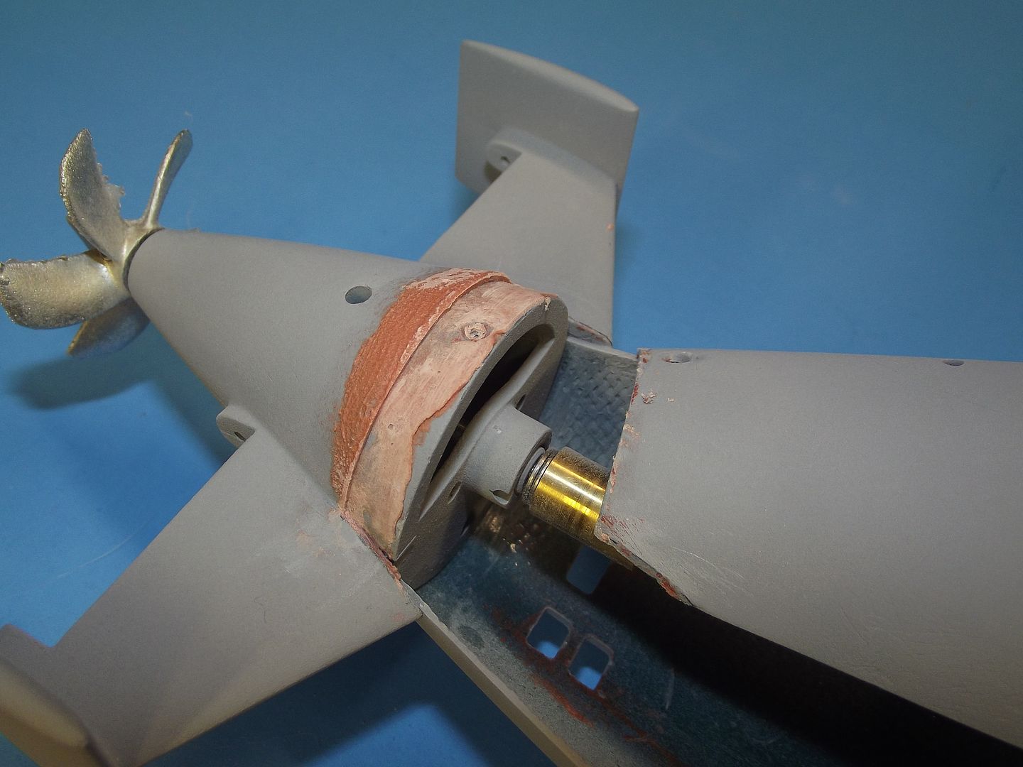
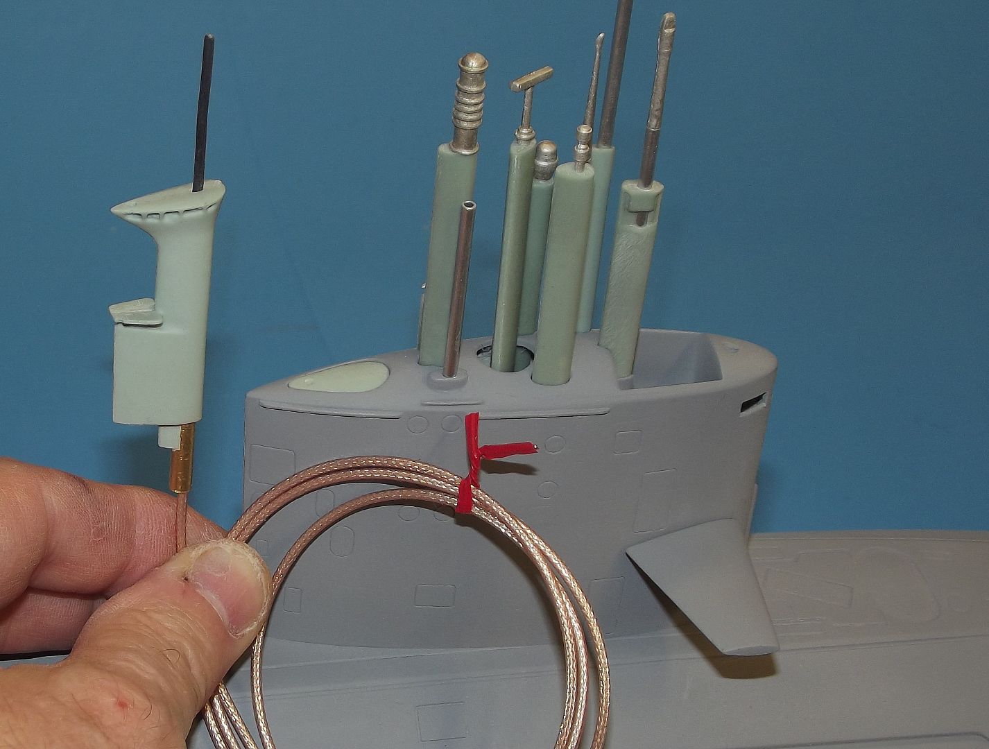
    I made three significant changes to David’s room temperature vulcanizing (RTV) rubber tool masters: I combined the two outboard vertical stabilizers to the tail-cone, three formerly discrete items become one; improved the mast foundation within the sail; and produced brand new scope heads and antennas that go atop the many ‘retractable’ fairings. As to the rubber tooling itself: I created a new set of rubber tools for casting of the resin parts; and created a disc type rubber tool from which white metal detail parts would be centrifugally cast.

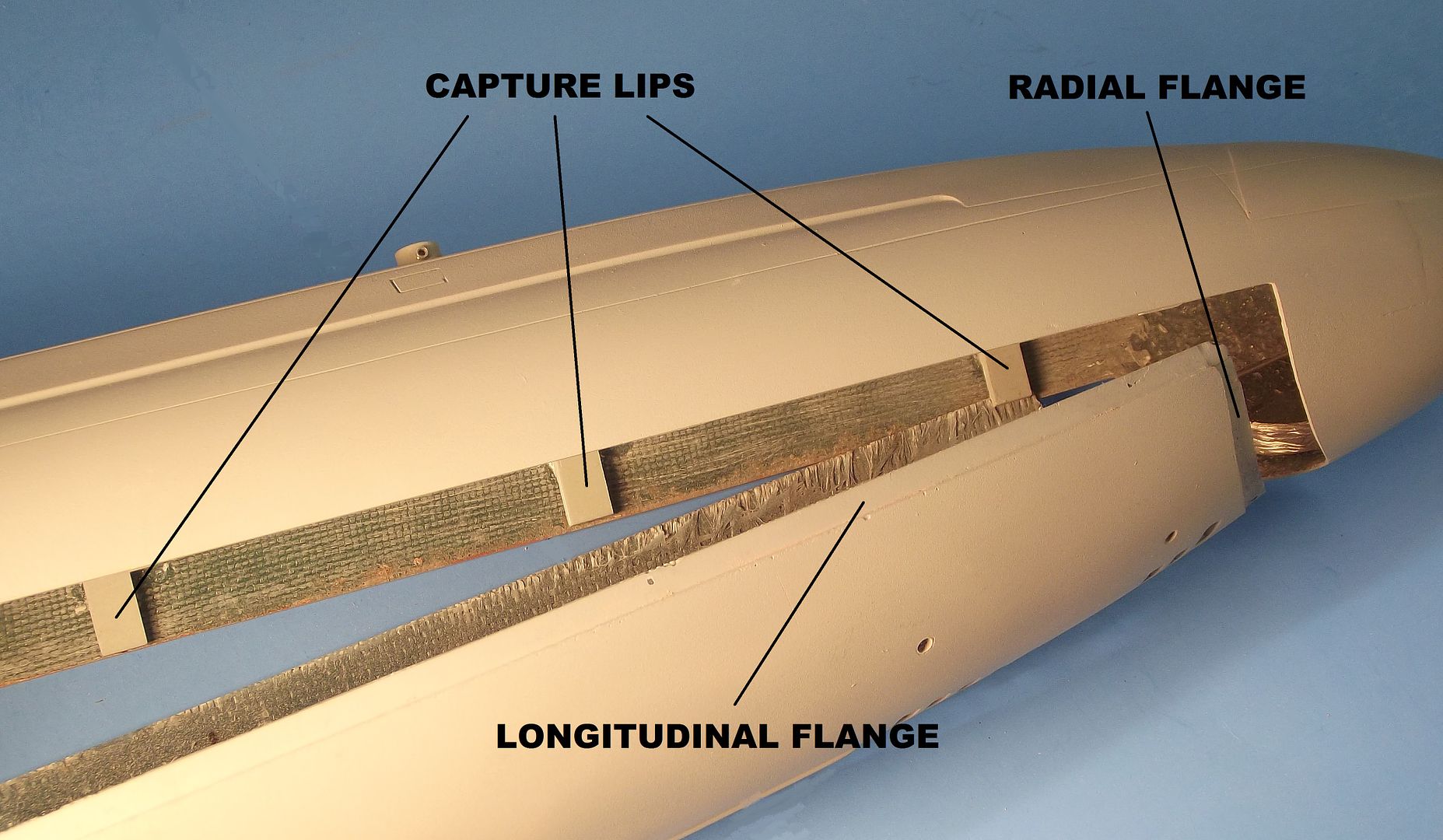
    I added cast metal yokes that connected the opposed rudders and stern planes, magnetic bell-crank for the sail-plane operating shaft, zincs, towing padeye, cleats, and capstans; cast resin Velcro strap and indexing pin foundation, snorkel head-valve blank (representing a retracted snorkel mast), and a set of hull closure capture lips (to hold the assembled hull half longitudinal edges in close alignment.


    Most of my documentation was secured during my navy diving days. I hold plan, profile, and detail drawings of the BARBEL in the form of an old copy of the BARBEL class piping Training Aid Book (TAB).

    These small, flip-page TAB’s used by crew members qualifying or re-qualify on systems unique to a class of boat. I got this copy while using it to validate red-tagging of hull penetrations prior to a security swim on one of these boats. I had the forethought to tuck it away for ‘safe keeping’. It is, of course, an unclassified document.

    I used TAB’s early in my navy career, initially when I transferred off a diesel boat to an SSBN where I re-qualify – the 616 class piping TAB, a coat-hanger and flashlight were my friends during that two-patrol process. The first few pages of any class piping TAB features accurate, detailed plan and profile drawings of the class as well as specific units of the class (such was the case of the WEBSTER, the only boat of the class to be outfitted with experimental bow planes… which drove the Sonar guys nuts near the surface in rough seas).

    Thirty-five years later I found a use for that BARBEL class TAB. The plan and profile drawings were enlarged to 1/96 scale and became primary source as I enhanced the kits production tooling.


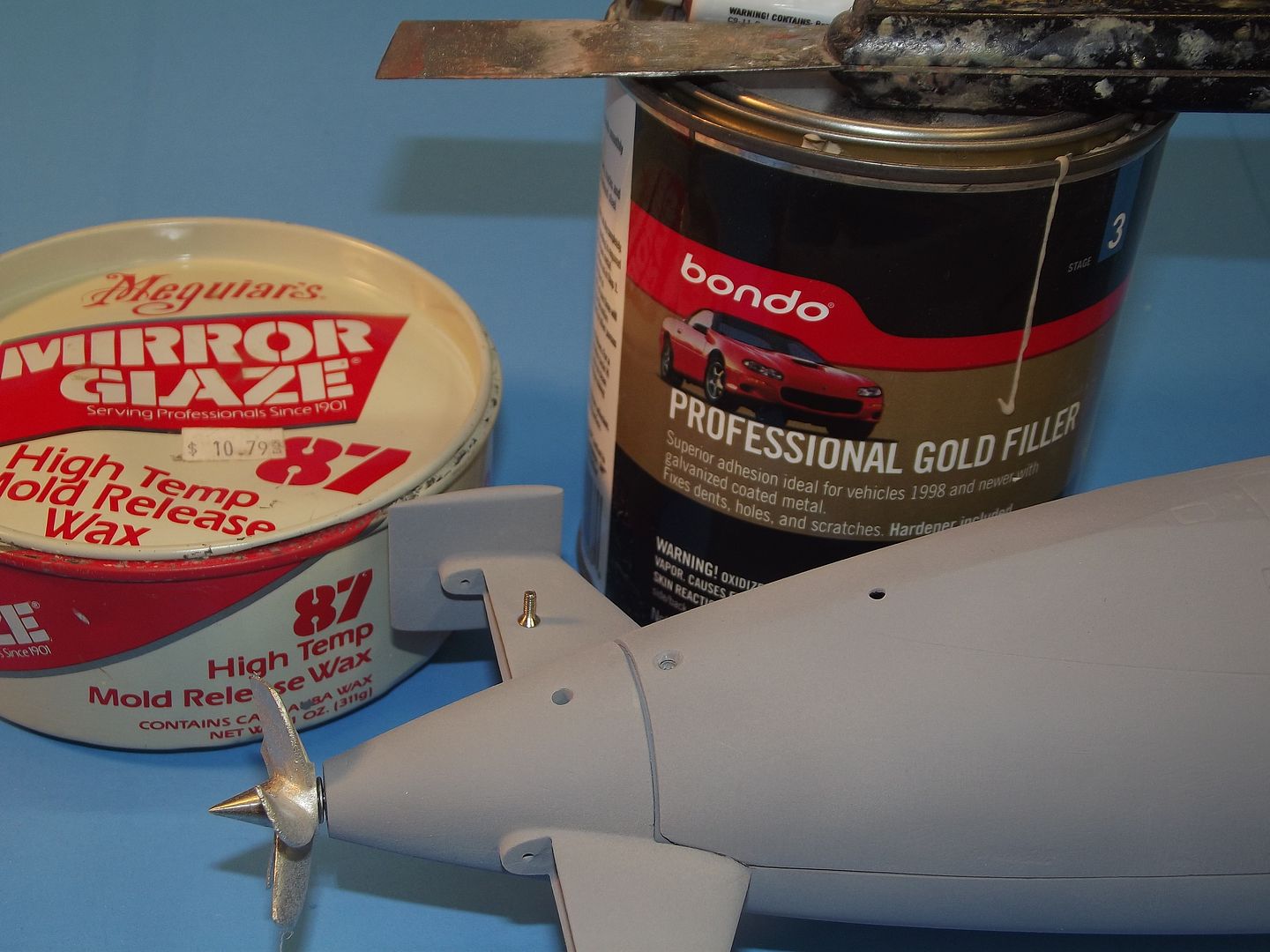
    The hull tooling, consisting of an upper and lower hull GRP tool was not changed a bit. However, new tooling for the resin and metal items started anew with reworked original and original masters. Above is a promotional picture showing the Caswell version of the SWM 1/96 BLUEBACK r/c submarine kit. The much improved tail-cone with attached vertical stabilizers, control surface yokes, and forward bearing foundation -- which also served as the radial flange that interfaced the tail-cone to the hull; and an improved sail mast foundation and antenna-scope array.


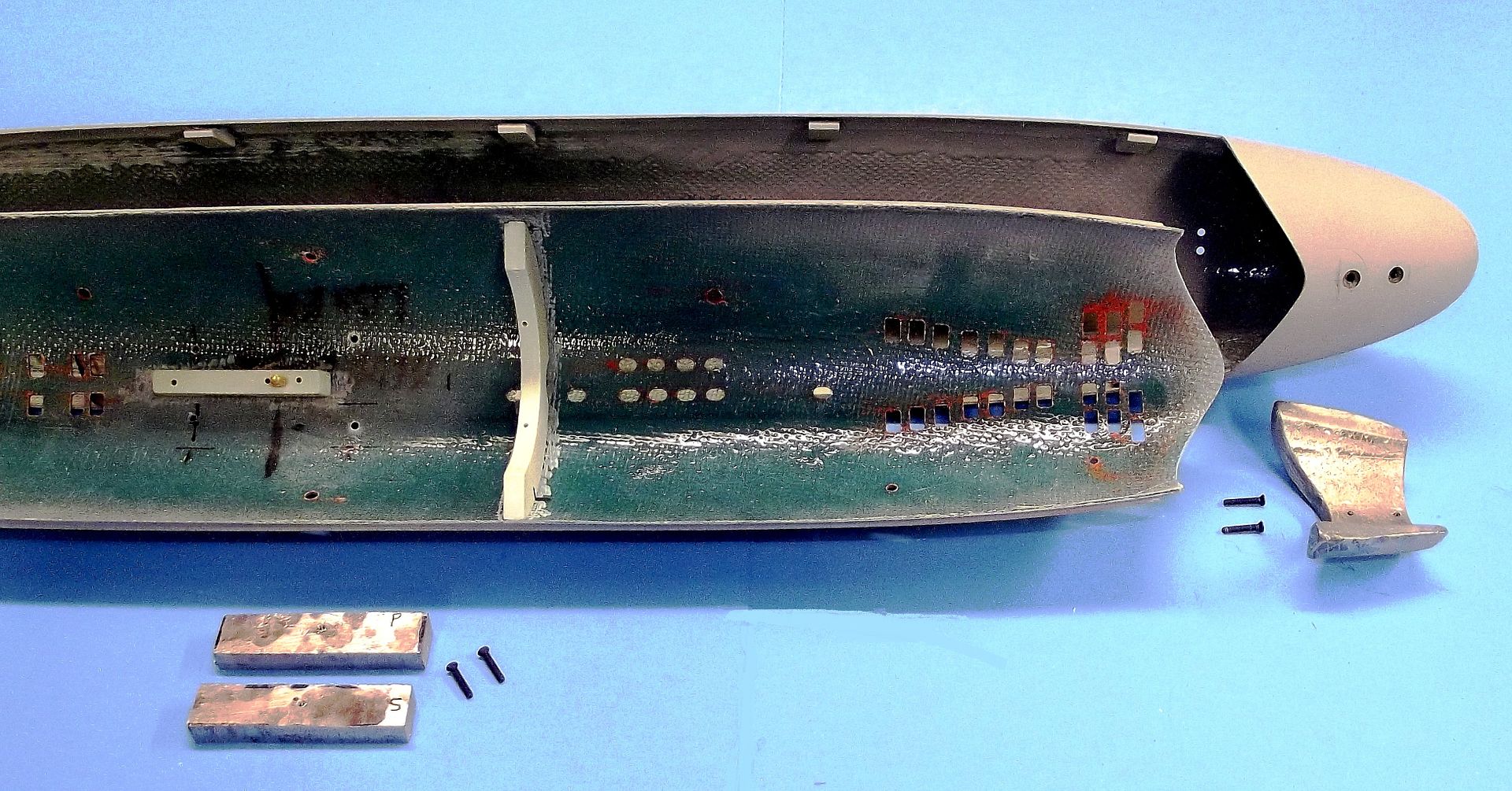
    Layup of the two hull halves went like this: Two highly buffed layers of mold-release wax; two spray coats of polyvinyl alcohol (PVC); a brushed thick gel-coat to fill all the deep voids and high relief items (engraved lines, bottom ‘bottom skids’, radial and longitudinal indexing flanges, and break between hull and superstructure); one laminate of four-ounce fiberglass cloth; and two laminates of ten-ounce cloth. The resin employed is West System 201 laminating epoxy.

    The home-made gel coat was a mixture of resin and phenolic micro-balloons. As is my practice, the laminating resin was tinted blue.


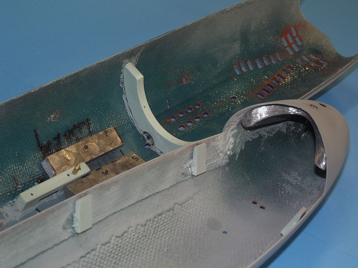
    A useful and time saving feature of the upper hull half tool is the removable portion which permits creation of an entire lower bow section -- all in one lay-up cycle. Being removable, this ‘bottom’ portion of the tool, that gives form to the entire bow, permits easy extraction of the laid up GRP part by simply removing the fasteners that secure the tool sections at the flange separation plane.


    GRP part removal from the tool is greatly aided by simply grasping the two longitudinal flanges of the tool and flexing the tool till the GRP part breaks free from the very slight bond between GRP resin and the PVA-wax release agent – the hull part literally ‘pops’ out of the tool. The lower bow portion of the tool has been removed to facilitate part removal.


    Though this shot presents the trimming of David’s KILO hull, the operation is the same for the BLUEBACK. It’s a simple matter of following the flange line imparted by the tool and cutting away the excess GRP. Use of a Carbide cut-off wheel is the tool of choice when cutting GRP. Glass will dull your carbon-steel tools in a minute, so where you can, cut the stuff with abrasives. Once you commit your box-store file to GRP, forever cosign it to such grunt work … it’s of little use for anything else.

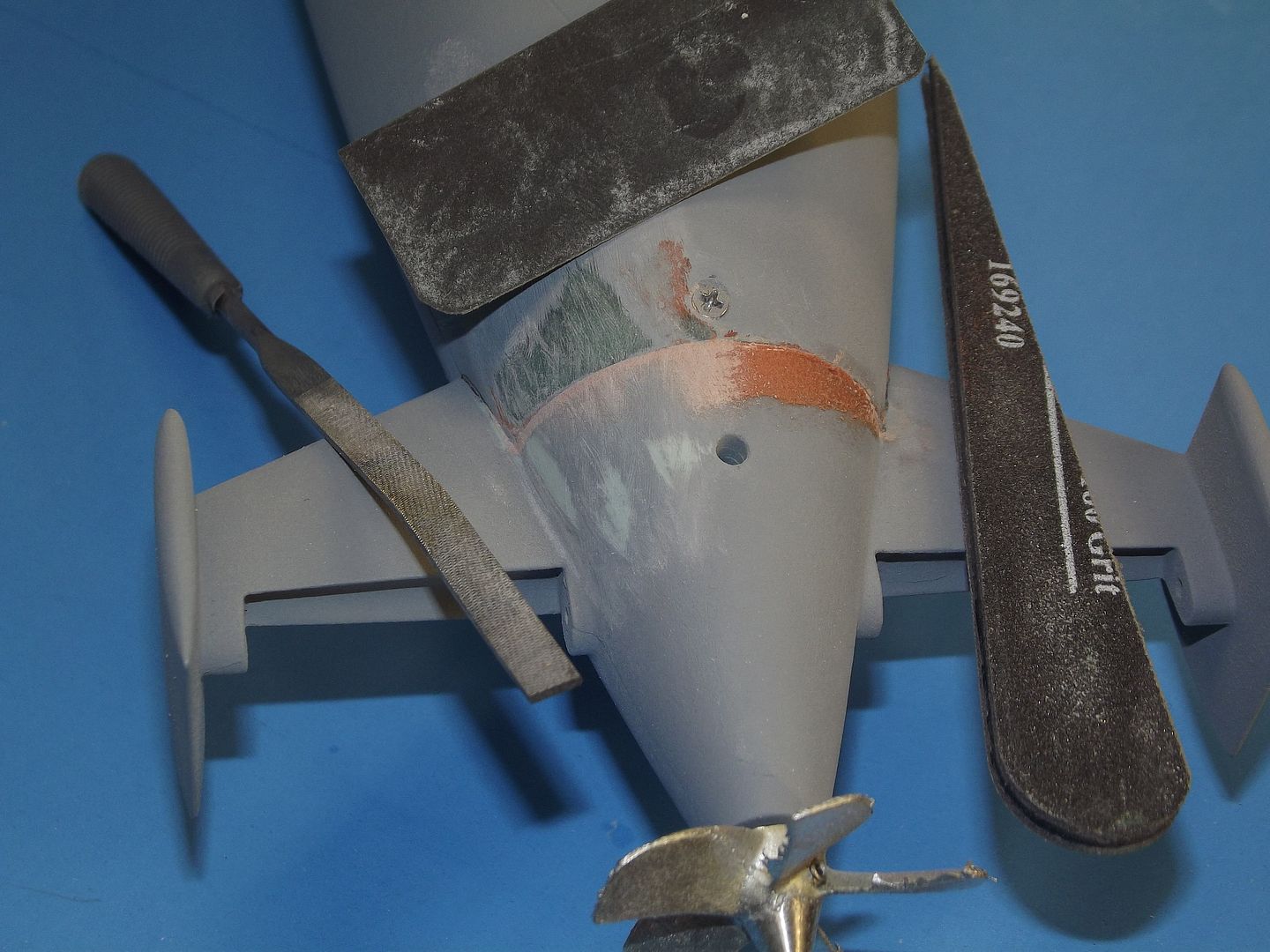
    Note the use of eye-protection and respirator -- nasty but necessary work. Final trimming to the line is done with sanding blocks.


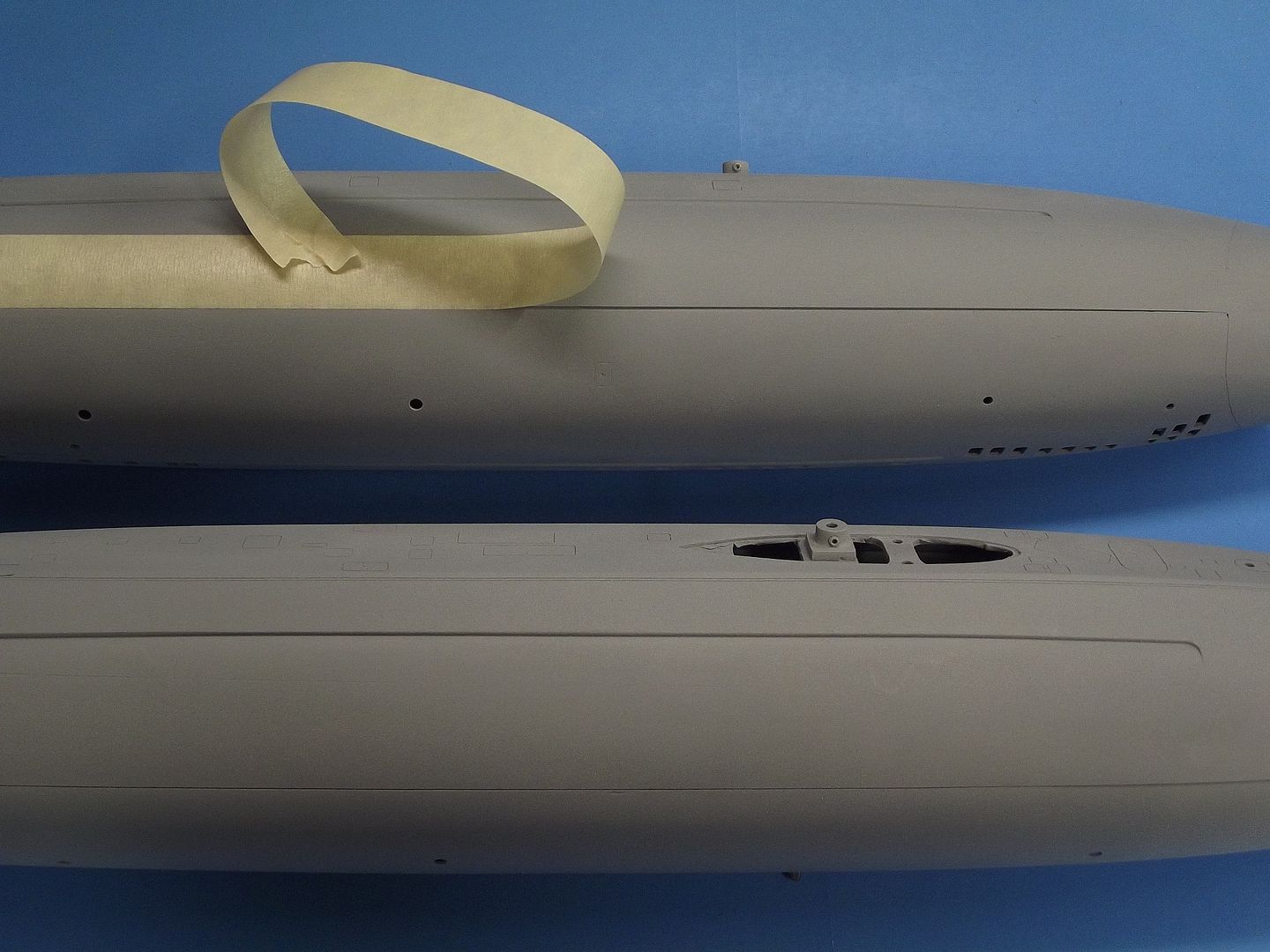
    When sanding flat the longitudinal edges of the upper and lower hulls Iuse a ‘super’ sanding block. Simply a large piece of shelving board with two whole sheets of #100 grit sandpaper contact cemented to it. The work is pushed back and forth over the sandpaper. For the tight areas like the bow of the upper hull I revert to files, sanding sticks and small hand-held sanding blocks.

    Who is John Galt?
  • redboat219
    Admiral
    • Dec 2008
    • 2735

    #2
    Where's the LIKE button here?
    Make it simple, make strong, make it work!

    Comment

    • He Who Shall Not Be Named
      Moderator
      • Aug 2008
      • 12253

      #3


      The forward radial break between upper and lower hull was cleverly devised, it following the actual sonar-window outline at the lower bow. Crafted this way the seam between the two hull halves at this point is lost to an actual prototype feature.

      The lower hull, in hand, has both an inset forward radial flange and inset longitudinal flanges that terminate at the stern. The inset equal to the wall thickness of the upper hull, forming the seating surface between the assembled hull halves.

      The closure methode on this model submarine, an many other r/c models that feature the equatorial split, requires only one fastener at the stern to insure a secure union of the hull halves when assembled. It’s the radial flange forward that captures the lower hull within the upper hull.


      To remove most of the part-release oil, the resin pieces are wipped down with with a lacquer thinner soaked abrasive pad and stiff brush, then wipped dry – this work done quickly to prevent any damage to the resin parts. The GRP hull halves are scrubbed with a slurry of water and scowering powder using an abrasive pad. This to remove any clinging PVA part-release film and wax -- exercising care not to abrade away edges and raised surface details.

      This is just the beginning of the preparation work done before any adhesive, primer, putty, or filler is presented to the raw model parts.

      Surface preparation is EVERTHING! Contaminates left on the model parts have the potential to bite me later during the last stages of painting – as masking tape is pulled away, so will the underlying primer and paint!


      Sanding tool that can negotiate the tight confines of the superstructure-hull break on both sides of the upper hull, as well as the right-angle areas like the sail cut-water and strakes are a necessity.

      Enter the double-sided sand-paper tool. Simply fold over a piece of sand-paper, abrasive side out, to produce a sharp crease, open it up and apply CA to the non-abrasive side, fold back up and compress till the glue cures hard. The result is a thin, stiff, double-sided sanding tool that only requires trimming of the edges with a pair of sissors, cuting the tool to any shape dictated by the job at hand.


      Commercially available ‘sanding sticks’ are also a must. They come in all sizes, shapes, and grits. But don’t get them at the hobby shop – the prices are outragiouse. The place to get these, in bulk, would be a well stocked ‘beauty supply’ or ‘nail care’ supply house.

      I save my abrasive sticks when the abrassive becomes unservicable. It’s a simple task to coat the face of the worn abrasive with CA and lay the stick, glue-side-down, onto the back of a piece of fresh sandpaper, then cut the sheet to the outline of the stick and the tool is back in business.


      Every surface of every part that will eventually be seen is wet sanded with #400 sand-paper. This is the only way of insuring a strong, long lasting bond between primer and substrate. Later will come a substantial amount of masking and painting. If the underlying layer of primer does not adhere tenaciously to the substrate, then desaster looms as the masking tape is removed and my paint job comes up with it! I either get this preparation work done right, or suffer the consiquences later.


      The range of plastics, resin, re-enforcing materials, primers, fillers, putties, adhesives and cohesive, woods, metals, and synthetic modeling board is broad and growing every year. Professionals know what material to use where and when. Material selection, chronology and methodology is everything; every specific thing in its proper place at the proper time. Experience teaches what material to use for the environment it will work within.

      An example of informed material choice and fabrication techniques are the two control surface yoke masters. The eventual yoke parts are used to connect the stern planes and rudders without interfering with the centrally running propeller shaft. As these masters would not only be used to make rubber tools, they would also have to be strong enough to actually function as I mocked-up the tail cone with all linkages before committing the arrangement to production tooling.

      The yoke masters started out as machine brass --an alloy of Copper-Zinc doped with Lead. The alloys attributes include easy machinability, readily solders, dimensional stability, ductility and malleability, and tough but not too tough. It’s the right stuff for this particular job.


      The yoke masters taking form. After boring and beveling machine brass round-stock on the lathe, each piece was soldered to its U-shaped ‘jumper’ – the jumper clears the centrally mounted propeller shaft. The central portion of the round-stock, under the jumper is cut away and the set-screw holes drilled and tapped. From this point the two yokes are hand-worked with moto-tools and files.

      The two yokes differ in dimensions and have to work in the tight confines of a narrowing cone within the tail-cone piece. The rudder yoke forward, the stern plane yoke just aft of that – making the stern plane yoke the shorter of the two.

      Note how small, otherwise hard to handle sub-assemblies -- like the bell-cranks pictured here -- retain a length of stock to serve as a handle. Only after the small piece is bonded to the rest of the structure is the excess material cut away and the nub finished off with a sanding drum and file.


      Most copper bearing alloys, even when scrubbed to an oil and dirt free condition, still refuse to bond effectively to anything but the self-etching primers. That shortcoming overcome by chemically treating the surface of the brass items to give them the ‘tooth’ (in the form of zillions of microscopic pits) needed to mechanically lock the adhesive/primer/filler to the surface of the oxidized metal. This oxidizing done by subjecting the work to an acid, in this case Ferric Chloride applied with a brush. Note the darkening on the surface of the metal as oxidation occurs. The ‘pickled’ part is dunked in fresh which spiked with baking soda. The high pH killing the acid. Rinsed with fresh water, then dried off, the pickled part will bond readily with other materials.

      And notice, at the top of the above shot, the acrylic handle with a length of 1/16-inch brass rod in it. A combination depth-gauge (that’s what the movable wheel-collar is for) and part holder. I have several of these, to handle specific bores of small masters or parts I work by hand.


      The outside diameter of the brass round-stock, coupled with the bore within, left little material for the threaded set-screw to reside in – particularly when considering the properties of white-metal which is what the model parts will be fabricated. White metal is relatively soft as metals go (but much tougher than resin) so the set-screw bores had to be long enough to resist stripping of the thread by excessive torque when setting the control surface operating shafts tight to the yoke. Heightening the length of the bore was done with baking soda and CA. Like this:

      I greased up two long set-screws and inserted them into the yoke. It was then a simple task to build up a mass of CA with baking soda around the set-screws. Each mass was worked with rotary bits and files until they fared in well with the metal components of the yoke. That of course abraded local areas of oxidized metal surface away. Before any putty could be applied, the parts were re-pickled. Pickling is done each time raw metal is revealed as the part is worked – this to insure later applications of putty/ adhesive/primer would stick properly.


      Who is John Galt?

      Comment

      • He Who Shall Not Be Named
        Moderator
        • Aug 2008
        • 12253

        #4


        The two yoke masters were mocked-up with the other masters that went atop or into the tail-cone master. Here you see the re-worked rudders, stern planes, and tail-cone masters. Note that the formerly separate vertical stabilizers have been bonded to the tail-cone master to ease the job of the eventual kit-assembler.

        Practical mechanisms have to be assembled and tested at the master stage to insure non-interference and correct operation. Such is the case with the tail-cone: can the rudders and stern planes swing to their limits without clashing with the internal yokes? Can the centrally running propeller shaft rotate without being hit by a yoke going through its extremes of motion? Can the two stern planes move without binding at the bearing points? Once the mechanism is validated as correct, work proceeded to the finishing stage of all masters.


        The initial design of the BLUEBACK kit had the vertical stabilizers as separate pieces that had to be assembled onto the tail-cones horizontal stabilizers. However, my philosophy of kit engineering is to offer the kit-assembler (the poor slob who has to stick everything together and get it working) as easy a task as possible. That meant integrating the three pieces into one homogeneous model part. Not noticeable to the casual observer I worked in a little toe-in of the vertical stabilizers -- this to give the model more dynamic stability about the yaw axis. (Look up, X-20 and examine the plan view drawings – what works in the air, works in the water … compressibility issues aside).


        Keeping with the make-it-more-easier-on-the-customer philosophy, I built a circular front piece – a separate forward bearing foundation that would nest into the forward end of the tail-cone.

        The forward bearing foundation holds the forward propeller bearing which, with the after bearing set into the extreme after end of the tail-cone, formed a propeller shaft support that assures correct, low drag alignment of the shaft along the hulls longitudinal center line. Additionally, this circular piece was stepped radially at each end – the smaller flange nesting within the tail-cone where it would be bonded. The larger forward extending flange would be screwed and glued to the lower hull. The portion atop that flange would become the seating surface for the after end of the upper hull.


        Jumping ahead a little to further explain what I did to enhanced the tail-cone. Here are cast resin and cast metal parts.

        Assembling your typical (non-toy) r/c submarine kit is hard enough. I sincerely feel it incumbent on the kit designer-manufacturer to give his eventual customer the best possible chance of successfully completing the kit and getting it to work well on and under the water. Providing a completely worked out tail-cone mechanism is but one example of that objective.

        David Manley produced the best kits of the time. With advancements in materials and techniques that transpired over the years I embraced those advances to make his kit even better.


        These are the original masters provided by Dave Manley when he transferred custody of the tooling to the Caswell Company. I’ve already started my upgrade here by replacing the original single-platform mast foundation with a two-platform variant – a more stable foundation insures all elements of the array remain parallel to one another. Dave incorporated the scope heads and antennas with their respective shafts and fairings. I did not. I elected to make the scope heads and antennas separate cast metal parts. I’m using Dave’s original parts here to check fit of the new fairing foundation.


        The scope heads and retractable antenna masters were either turned or hand cut from machine brass. Just a portion of the documentation used as I gave form to metal is posted above the work-bench.

        My work-space has several dedicated work stations -- this one set up for lathe work -- giving me the ability to perform a specific task, and when that is completed, to move on to another work station for further work. It’s vital, if work is to be done in a timely manner, to avoid a situation where you have to re-rig a single work station for every task involved in a project. My days of working out of a closet are way behind me! At one end of the shop everything is in place for grinding, milling, and drilling; and at the other end of the shop everything needed to pressure cast resin and cast metal is at hand. A rational shop set-up is everything if quality work is to be produced in a reasonable amount of time.

        Before the age of CNC, if you visited a professional machine shop you would see an arrangement of machine tools and work stations very much like mine today.
        However, CNC and 3D printing has changed all that, and is destroying the Craft of model building. No computer controlled machining or build-up here. EVER! I’ll be the last dinosaur in this game.

        Ever see a diamond-cutters workbench? The table plane is about even with the Jeweler’s chin. This puts the elbows up high and offers a stable support for the hands. Salvaged hospital tables – the type that can be adjust to height and sit on roller-casters – are used the same way in my shop, for hand-crafting of detail parts.


        Chucked up and being worked here is the stem of what will be the radar antenna. In hand are the VHF antenna, attack scope (type-2) and search/night scope (type-8).

        I’m holding a little go/no-go gauge used to insure I got the base diameters to the scope heads and antenna masters to the desired 1/16-inch diameter. Internal 3/32-inch diameter aluminum tubes, encapsulated in the fairings, project down to fit the mast foundation piece, while the upper end, cut flush with the top of the fairing, afforded the 1/16-inch inside diameter to support the scope head or antenna atop it.


        Solder is an adhesive – the joining of two (or more) parts through the introduction of a third part which bonds readily to the parts being joined. Soldering, like brazing, is a metal adhesive that is introduced in the liquid state and which, once applied to the union site, freezes to a solid at room temperature effecting a bond between all parts subject to the wetting of the solder while it was in the liquid state. Soldering can be looked upon as an extremely hot version of the glue-gun found in almost all kitchen nick-knack drawers. Soldering and brazing is not welding, i.e. there is no fusion of the joined metals.

        The strength of any non-fusion bond is dependent on the mechanical union (proximity) of the parts as well as the strength of the adhesive. Demonstrated above is proper sub-assembly design, the support-columns of the radar and loop antenna fit holes in those antennas providing great sheer, tension, torsion, and compression strength. The solder only holds the parts in place.


        Appreciating the relative weakness of a solder joint, care is taken to arrange the parts to offer the broadest adhesive area where the solder will be applied. In both cases, presented above, the solder not only bonds at the base of the unions, it also runs up and down to bond the support-column or pin within the antenna and foot-ball piece. Know your materials – their abilities, and shortcomings.

        Who is John Galt?

        Comment

        • He Who Shall Not Be Named
          Moderator
          • Aug 2008
          • 12253

          #5


          I used hemostats, pin-vice, alligator-clips, and fingers to hold the parts as they were refined and assembled with the aid of solder.


          The original resin mast masters were acceptable, but had to be lengthened a bit to account for the greater distance they had to pass down into the sail to make up to the new two-platform mast foundation I worked out. You see the grafted fairings here as well as a test fit of the brass scope heads and antennas. This is one busy looking sail!

          Note the forward most fairing is not nested in the mast foundation. This fairing is for the #1-scope (a type-8 with big optics, which resides in a receptacle at the after end of the bridge cockpit. Other than an enhancement at the top of the fairing, nothing was changed from the original.


          From the second-world-war up to recent times the US Navy has made use of two periscopes of different capabilities: a narrow headed periscope (producing a very small ‘feather’, or wake) for close-in attack work; and a large headed periscope, one with a head containing optical elements big enough to gather enough light to make it useful at night and at long ranges. The BARBEL class boats made use of the type-2 attack scope; and the type-8, search-night scope. The type-8 scope head even had radar antennas for range and bearing to target!

          The 1/96 scale type-8scope seen here over one of the many documents I used to render the shape of the scope head and the specialized fairing that could be raised up over the scope cylinder when operating at significant speed underwater.


          The type-8 periscope and retractable fairing seen to good advantage here. The rather involved looking geometry at the top of the fairing is a ‘wake attenuator’. Though the model is not exactly like the prototype, it’s a lot closer than doing without it – the distinctive eye-catching element of this display is a short length of periscope tube seen just below the attenuator side-plates.


          It’s American practice to identify the scopes by their fore-aft position on the boat. That makes the forward thick headed type-8 night scope, the #1 scope. And the much smaller headed type-2 attack scope, the #2 scope.

          Here I’ve cut down and sculpted the tip of the #1 scope fairing master to better represent the wake-attenuator. Without this wake damping device a real submarine, at speed, would throw a rooster-tail wake, alerting even the most dim-witted adversary look-out as to the submarines position.


          A new casting from the original sail tool produced the unit I would enhance with additional scribing and provision of a more robust two platform mast support foundation. Once the new scribing was engraved and the old scribing cleaned up, and deepened, I added the leading edge cut-water and horizontal strakes near the top of the sail. This became my production sail master.


          With all the masters completed, and mocked-up to insure coordinated fit and operation, they were closely inspected and any flaws identified corrected. The masters were then used to create the production rubber tooling needed to make production parts.

          Note that the clear resin propeller – an original part from the package received when the SWM submarine tooling and masters were transferred – was kept as is. I found no faults with it and used it neat to make the propeller tool.

          A quick review of the new and enhanced kit masters: I engineered a more robust mast foundation comprising two spaced platforms cut from polystyrene sheet; new antenna and scope heads formed from machine brass; the original #1-scope fairing was sculpted to capture the suggestion of the wake-attenuator at the top of that fairing; provision of a WTC/SubDriver 2.5” diameter cylinder saddles, and Velcro-indexing pin foundation; capture lips to secure the two hull halves more tightly together after assembly; integration of the vertical stabilizers with the tail-cone; provision of an improved running gear arrangement within the tail-cone; inclusion of purpose built yokes to connect the opposed control surfaces; inclusion of a magnetically coupled sail plane operating shaft bell-crank; and cast white-metal scope heads and antennas, zincs, cleats, towing padeye, capstans, and propeller.


          The tail-cone and sail masters were used to create three-piece room temperature vulcanizing (RTV) rubber tools. In such cases I most often resort to a proper six-sided flask -- basically a box affair such as the above. Constructed of ½-inch, veneered shelving (particle board). All pieces secured with deck screws to afford easy assembly/disassembly of the flask.

          These masters feature hollow interiors that, in rubber form, are cores that displace resin to form the thin walled, hollow cast resin parts. The flask is used to contain the liquid rubber during tool manufacture and used to keep the tool sections together during the casting of production parts.

          Note the horizontally projecting rod from the sides of the sail master; this will form a channel that, in the rubber tool, will suspend another rod that will produce a perfectly placed and sized bore in the sides of the cast resin sail through which the sail-plane operating shaft will pass. The vertical tube at the center of the tail-cone master will form a bore in the eventual rubber core and tool halves. A like sized tube placed in the tool during tail-cone part casting will produce the bore through which the after propeller shaft bearing will fit.


          The masters made of white metal and brass were pickled and primed. Here I’m using double-sided tape to hold the masters as they were spray coated with Nason automotive lacquer acrylic primer. These masters, as well as the rudder and stern plane yokes, used to give form to the molding cavities of a disc type centrifugal rubber tool – that tool used to cast white-metal production parts.


          Who is John Galt?

          Comment

          • He Who Shall Not Be Named
            Moderator
            • Aug 2008
            • 12253

            #6


            Rubber tool design and manufacture is a topic for another, more thorough discussion. But, here you get an idea of the process: the masters set into masking clay, permitting creation of the tools first half without danger of encapsulating the masters. The dimples pressed into the clay flange faces form an array of indexing positives onto the first mold half that will be captured in negative when the second half of the rubber tool is poured over that.

            With the exception of the two flasks (tail-cone and sail masters) the eventual tools will be simple two-piece units.

            I’ve found the BJB platinum-cured silicon RTV rubber, TC-5050, to be the ideal all-round mold making rubber. This stuff finds utility when laying up GRP, casting raw resin, or casting low-temperature melting metals. TC-5050 is relatively hard, chemically stable in liquid or solid state, has a very high cycle-life, and broad temperature tolerance.


            Ready to pour the first half of the centrifugal tool. The masters have been pushed about half-way into the masking clay and runners -- radiating from the central sprue mandrel – formed here as deep channels. The first half of the RTV tool will capture the runners as positives, which in turn will produce the negatives when the second half of the tool is poured.

            The two smaller mandrels will form bores through which the securing studs of the centrifuge spin-plate pass. Those studs will later accept compression nuts that will clamp the spine-plate atop the tool, holding it securely and also compressing the two tool halves together tightly.

            A masking tape dam is wrapped around the disc to contain the catalyzed liquid rubber until it cures hard.


            The propeller master was outfitted with a very long sprue forming mandrel. Though a two-piece tool, the upper half is built up of two pours of RTV rubber: the first to continue the disc shape of the eventual lower tool half; then, after removal of the masking clay, the lower half was poured; the two halves flipped and the sprue forming tube re-inserted; a smaller cylindrical containment made up to the top of the upper half and more RTV rubber poured in to form a tall sprue channel into which the liquid metal will be poured. The taller the sprue the more pressure presented to the lower portion where the tool cavity is, so the quicker the fill, insuring a complete casting with no voids.


            When dealing with a tool of complex architecture, such as the tail-cone, it’s good practice to first generate napkin-studies and from those a more refined full-scale set of isometric projections, such as the ones you see here.

            It’s one thing to ‘think’ in three-dimensions. But arrogant assumptions are revealed as interference points and paradox flaws once the concept is drafted out as a three-view drawing. Only after a checked working drawing is in hand do I make the jump into flask fabrication.

            I don’t need a frig’n CAD program to tell me I’m a part-time dump-ass. I can do that all by myself! Keeping my hands involved in every aspect of model building is how I keep my aging brain in the game, boys and girls. I’ll be a slobbering idiot soon enough – no need to surrender to the machines any quicker than I have too!

            The tail-cone master was suspended within the flask by a 3/8” brass tube projecting out from the extreme after end of the master. Into the open cavity of the master clay was formed to prevent entry of the casting rubber, this clay extending up to the surface of the initial pour, which would encapsulate the rest of the master in one big, intimidating block of rubber.


            After the massive block of hard rubber was stripped of the flask walls I removed the two rods that gave form to rudder and stern plane operating shaft bores within the tool. (Later, when the tool is assembled in preparation to casting, brass wires would be inserted, they giving form to the bores within the cast resin tail-cone. And it would be through those bores that the operating shafts of the rudders and stern planes would run).

            Notice the use of a popsicle stick to hold open the initial slit as I stab-and-slice. The prying permits the mold to tear when the incision gets to within 1/8-inch of the master – avoiding any knife damage. This is an acquired skill. The slitting continues around the four faces until the master can be extracted (and examined for damage).


            The nerve-wracking task of slitting the block into two halves got underway as I consulted the drawings, reminding me where to slit with a knife and, more importantly, where not to slit. The slicing process started at the sides of the block, cutting a shallow wavy line down the sides avoiding the master within. The uneven cut line producing two flange faces that would key together perfectly when the tool was prepared for casting.

            I’ve re-inserted the rods to the master. Both flange faces of the halves are given a heavy spray coating of Mann 200 part/mold-release silicon spray (used to render non-stick surfaces for both tool and part manufacture).


            The third part of the tail-cone tool has to be made. The tool halves are reassembled, the flask assembled around them and another mix of catalyzed rubber poured atop the two hull halves forming the core needed to render hollow cast resin parts. But first these indexing dimples were cut out of the top of the two hull halves. When the third part of the tail-cone tool is poured it will capture, in positive form, the dimples and thus form a perfect indexing array that will hold the third rubber piece in perfect alignment with the other two – this assures that the core piece, an element of the third tool piece, will be suspended correctly within the cavity presented by the initial two hull parts.


            Preparing to pour the third part of the tail-cone tool starts with inserting the master, encased within the two halves, and assembling the flask to hold everything together. Mold-release is sprayed over the top face of the tool, and the flask lid. Note the clay gasket at the top edges of the still open flask lid. The clay serves two functions: First, it keeps the liquid rubber from leaking out. More importantly, the slight stand-off of the lid from the edges of the flask produces a slight excessive height to the third rubber part. Later, when casting, the lid can be compressed a bit to squeeze the tool parts within tight, resulting in castings with the minimal amount of flash.
            Who is John Galt?

            Comment

            • He Who Shall Not Be Named
              Moderator
              • Aug 2008
              • 12253

              #7
              right along side of that unfinished KILO of yours.

              David
              Who is John Galt?

              Comment

              • Subculture
                Admiral
                • Feb 2009
                • 2119

                #8
                What's the advantage of slicing a one piece tool over making it in two parts with registration?

                Comment

                • He Who Shall Not Be Named
                  Moderator
                  • Aug 2008
                  • 12253

                  #9
                  Originally posted by Subculture
                  What's the advantage of slicing a one piece tool over making it in two parts with registration?
                  I see only liabilities with the slit type tool, Andy. That's why I'm an advocate of the multi-part tool.

                  David
                  Who is John Galt?

                  Comment

                  • He Who Shall Not Be Named
                    Moderator
                    • Aug 2008
                    • 12253

                    #10


                    This is how the three-piece tail-cone tool breaks down. When assembled a 1/16-inch rod runs from one vertical stabilizer cavity, through the annular space between tail-cone cavity and core, the tail-cone, and on through the other vertical stabilizer cavity. And a 1/8-inch rod passes, at a right angle to that, through the tail-cone cavity annular space and core. Both of these rods pass through the entirety of the tool and must be extracted from the tool before the master can be accessed (same for the eventual resin tail-cone parts cast in this tool).

                    Those two rods will eventually produce bores in the cast resin tail-cone part through which the stern plane and rudder operating shafts will pass.

                    A ¼-inch tube projecting through the tail-cone suspends the master within the flask during tool making. The cavity that tube produces becomes the bore in the cast resin tail-cone that will accept the after propeller shaft Oilite bearing.

                    The complexity of this type tool dictated by the complexity of the resulting cast resin part: a hollow tail-cone, outfitted with the two vertical stabilizers, ready to accept the after bearing and control surface operating shafts. Worth the effort!


                    At this point I’m half-way through creation of the BLUEBACK rubber tools. All this is an up-grade to the original SWM kit; reworked masters as well as new ones used to make rubber tools I’m comfortable using.

                    The first-half of the two piece tools have been pulled away from the masking clay and masters, mold-release spray applied to the cavities and flange faces of the tool halves, and the masters re-set into the cavities they formed. I then built up masking tape dams around the tool halves and poured the second halves of the tools.
                    Before laying in the masters each tool half was weighed and that number recorded (marked on the side of the tool half with Sharpie-pen).


                    Masking tape dams in place. I’ve found that the ‘low tack’ type blue masking tape does not have the Sulfur content that traditional tan colored masking tape has, which inhibits the cure of Platinum type RTV rubbers. Next, a liberal coating of Mann 200 silicon part-mold release was sprayed over the masters and flange faces – this vital step insures a no-stick situation between the two halves of the eventual tools. If you don’t get this right then the masters will be entombed and you’ll have to cut them out with disastrous results!

                    The total amount of RTV rubber for the job-- determined when the first halves were weighted (the second halves should weight the same) --was mixed and de-aired in the vacuum chamber (to remove air-bubbles entrapped in the mix as the catalyst was stirred in). Just before pouring the second half of each RTV rubber tool it was placed on a scale and the catalyzed rubber poured in until the desired weight of material was in place. This practice insures tool halves of equal thickness and avoidance of wasted RTV rubber – the stuff is expensive!


                    After the second half of a tool is cured hard, it is peeled away from the first half. The masters are removed and placed into safe storage for possible future use. I typically get 50-80 cycles from a tool when casting polyurethane based resin. In the old days I was lucky to get 30 cycles, but the RTV rubbers and cast release agents have progressed so much so that today I run through an entire kits production life with just one set of rubber tools.

                    Note the brass round-stock used to give form to the sprue and main runner channels. You can make out the raised beads formed from the impressions pushed into the masking clay -- to form vent channels needed to displace air as resin is introduced into the tool cavities. The vent channeling presents as a positive on the first tool half, and as a negative on the second tools half.


                    The positive vent channeling has to be turned into negative channeling. This done with a tube-cutter, its end sharpened and a portion of tube removed to permit the cut channeling to run unobstructed through the cutter as it’s pushed along, as you see here.


                    The tube-cutter did not take it all the way to the top of a cavity, that final quarter-inch or so done with a sharp X-Acto blade and the trench made very, very narrow and shallow where it terminates at the cavity. The care exercised here with the vent channeling will later produce cast resin parts that easily break away from the solid resin vent pieces without losing any surface material.


                    The disc type tool seen here is unique in that it is used to form metal parts. The metal is an alloy of Tin (95%) and Antimony (5%), with a melting temperature of about 500-degrees Fahrenheit. The maximum operating temperature of the BJB, TC-5050 platinum-cured RTV rubber -- which I use for almost all my rubber tools -- is 600-degrees Fahrenheit.

                    Centrifugal force is the agent that pushes the molten metal into the tool cavities. The tool spins along the axis of the single sprue hole atop the upper half. Once spinning the molten metal is introduced through the sprue and the spinning sends the metal chasing through the runners and into the cavities of the tool that give form to the metal as it quickly changes state from liquid to solid.

                    I’ve pulled the just formed second half of the tool, seen to the left. Note that the runners on that half are positives and have to be trenched out with the tube-cutter (normally used to cut vent channels). No vent channels are required with this type tool as the force of the heavy metal slamming into the cavities momentarily unseats the flange faces of the tool halves (even though they are clamped shut) enough to ‘burp’ out the displaced air. This results in nearly flash and nub free cast metal parts.

                    (Ever wonder why you don’t see vent channel artifacts on injection formed kit parts? Same mechanism – the tool, even though metal, distorts a bit during injection and the displaced air leaks out across the flange face).


                    Alumilite polyurethane casting resin is the material of choice for cast resin work. The part-A and part-B are mixed equally by weight. At normal room temperature the mixed resin has a pot life of about ninety-seconds – plenty of time to mix, pour into the tool, get the tool into a pressure pot and get it under pressure (typically 30 psi).

                    Here you see most of the items needed to prepare a rubber tool for casting: a resin mixing container and mixing stick; a weight-scale for accurate measurement of the two-part resin; Mann 200 part release spray to reduce chemical interaction between the curing resin an tool cavities; clamping strongbacks and rubber bands; and talc (or corn starch) to dust the tool cavities prior to assembly.

                    The Talc is hydroscopic; it absorbs water and also serves as a wick to pull the resin into every crevasse of even the most complicated cavity. The talc also serves as an additional barrier between resin and rubber. The talc is introduced to the open faces of the tool halves shortly after laying down a coat of part-release spray -- the gummy surface of the cavities then able to hold a very thin layer of talc. Excess talc is shaken out of the tool before assembly and pouring.


                    Pressurizing the tools to 30-psi acts to crush any entrapped air-bubbles into solution, greatly reducing the possibility of any voids in the cast part. The pressure has to be applied before the resin hardens, and must be maintained during almost all of the curing process, about twenty-minutes on a warm day – longer if it’s cool.

                    The pressure pot itself is a spray-gun paint container and comes complete with a 60-psi safety-valve. A must-have feature in my opinion. These pots are available at Harbor Freight or any number of distributors on the Net.

                    Who is John Galt?

                    Comment

                    • He Who Shall Not Be Named
                      Moderator
                      • Aug 2008
                      • 12253

                      #11


                      Ninety-percent of all my resin casting tools will fit a standard paint-pot. Here three tools sit on a simple caddy I made from shelving board and a central all-thread handle. The tools are set on the caddy, filled while conveniently on the table, then lifted and dropped into the pot and the lid quickly secured. It takes only a few moments to get the inside to the two-atmosphere pressure required for bubble-free castings.


                      For those rare occasions where the rubber tool is either too long or tall for thepaint-pot type pressure vessel, I employ one of these custom made pressure pots made by my old Diver buddy, Phil Kordich. Of varying length these three pots usually load from the side, as you see here, but they can be set on end for tall tools. With an inside diameter just a tad under 10-inches these pots can handle anything I’ve ever had to cast or pressure treat.


                      Here are arrayed all the rubber tools used to cast resin parts for the SWM 1/96 BLUEBACK kit. The strongbacks are cut from half-inch thick shelving – this stuff does not warp, and because of the vinyl veneer is very resistant to any resin that gets onto the face of the strongback. The clamping force is provided by rubber bands.

                      Clamping force of the multi-piece tail-cone and sail tools is achieved by the flasks built to both form the tools outboard faces and hold the rubber pieces in perfect registration during the casting process.


                      Resin casting tool design, 101. Note the tall sprues – some of those sprue channels actually cavities that themselves produce resin parts. Leading from the sprue are runners that run to the bottom of a cavities. And, atop each cavity, you see vent channels, there to permit the escape of air as its displaced by the resin.


                      After casting a resin tail-cone piece, the rods that gave form to the castings rudder and stern plane operating shaft bores were pulled out. That done the two side pieces of the tool were pulled away, leaving the cast resin tail-cone piece still connected to the sprue and runners that run through the center of the core – the resin part is still captured between the third tool part through the sprue channel residing within the split core section.

                      The central hole is the sprue, the two either side of the tools top are vent risers leading from the outboard vertical stabilizers and leading edges of the horizontal stabilizers of the tail-cone piece – these areas being the high point where bubbles would otherwise collect.


                      Extracting another cast resin tail-cone piece from the three-piece tool that gave it form. In foreground is another casting, yet to have its flash and runner nubs removed.The core of this tool produces the deep, thin walled cavity of the tail-cone part – and its through the center of the rubber core where the sprue channel resides, distributing the resin to two adjacent runners that lead to the horizontal stabilizer cavities. Complex? Yes. But necessary.


                      Some clever tool design on my part here:to avoid placing the sprue and its runners anywhere on the surface of the tail cone piece I put the sprue channel through the center of the core, with right-angle runners from the base of the sprue channel to the roots of the two horizontal stabilizers. To prevent entrapment of the cast resin part during extraction, the core is split to permit the resin sprue and attached runners to pull free as the core is yanked off the casting.


                      This is how the three-piece sail tool fits together. The elastic property of the rubber permits all sorts of deep-draft sins that solid tools will not permit. You see this evidenced in the bridge well and deep recess for the snorkel induction head. And there are negative draft items here too: the three deadlight projections on the core – if the tool were not rubber these would have sheared off as the master was pulled away from the tool. Also, at the base of the core are recesses that form foundations for the eventual machines screws that hold the cast resin sail down on the GRP deck of the hull, these have serious negative draft to them. I modified the master only slightly from Dave Manley’s original work. It’s simply amazing how much detail he worked into a one-piece casting – and with a slit-type tool as well!


                      A characteristic of the spin-casting process is the need to arrange all the forming cavities in one or more concentric circles around the center of rotation. In one of the two tool halves is punched a sprue hole at its center.

                      Foreground, left is the first shot from the tool – note the heavy flash on the cleats, radar and towing-padeye. That shot told me where to shim the tool under the casting machine compression plate, to make a tighter fit between the tool halves. A much improved shot of metal is seen to the right – the shims now in place (glued to the upper half of the tool) consistently good shots became the rule of the day.
                      Who is John Galt?

                      Comment

                      • He Who Shall Not Be Named
                        Moderator
                        • Aug 2008
                        • 12253

                        #12


                        The machine used to spin the disc type tool is a modified blood-separation centrifuge. These machines are available on Evil-Bay or a medical supply broker. Note that I control the speed of the machine with an old style Dremel speed-controller. To the right you see an electric melting ladle – designed to melt lead (used most often by the gun re-loader guys), it’s suitable for melting the ‘leadless solder’ which is the usual labeling for the alloy used -- in our circles called, white-metal.

                        Removed for clarity is a ring shaped ‘splash shield’ made of heavy cardboard – this vital piece of safety gear catches any spilled molten metal that overflows from the sprue during the pour. Without the shield you get a face full of hot metal, which, I can assure you … gives one pause. Eye protection is a must.


                        Gravity is the agent that insures a successful pour of molten metal with this tool. Note the long sprues at the after ends of these cast white-metal propeller blanks. The taller the sprue, the greater the pressure-head, the more complete the fill of the tools cavities. And speed of fill is critical with the quick freezing white-metal.

                        Prior to tool assembly a greased 1/8-inch diameter stainless steel mandrel is inserted into the lower half of the propeller tool. This gives form to the metal propellers bore during the casting operation.


                        Just plug in the ladle, drop in the white-metal (‘leadless solder’) and wait about ten minutes for the metal to reach pouring temperature, and things are ready for a pour.

                        A typical gravity-pour type two piece tool is seen ready for a pour. Clamping force is gravity acting on the four lead weights sitting on a strongback atop the upper tool half. The long pouring sprue is seen projecting from the center of the strongback. The taller the sprue, the greater the pressure head, the greater the pressure at the base of the tool.

                        The long sprues atop the propeller blanks are sawed off and the metal re-used. Unlike resin, almost all metal be it sprue, channels, vents, risers, runners or shaving – they are all reclaimed.

                        Into the side of a cast propeller is drilled a hole which is threaded for a 4-40 set-screw. This set screw later bears against the flat of the propeller shaft, securing the propeller in place.


                        Each propeller was mounted on a lathe installed 1/8-inch stainless steel rod and its set-screw synched down tight. The chuck was brought up to speed and this special angle-cutting tool-holder used to cut the exact cone-angle into the sprue to turn it into a proper propeller dunce-cap. In my hand you see before and after results of the lathe work.


                        Wherever possible I use a file to prevent abrading away material next to the raised flash. One element of good tool design is the placement of the flange plane(s); where the segments of a multi-part tool meet. To arrange the flange plane away from areas of the part that would be subject to accidental hand-tool strikes.


                        As the resin parts are trimmed and made ready for de-greasing all mechanisms, such as the bow planes, sail masts, and stern control surfaces were test-fit together and operated by hand to insure that no interference problems existed, and to again familiarize myself with what-goes-where later during permanent installation after all painting, markings, weathering, and clear-coat had been accomplished.

                        An ounce of prevention and familiarization here negates a ton of work later.


                        It’s much easier to work the mechanisms contained within and on the tail-cone while it’s still off-hull. Here I’ve installed the propeller shaft and bearings and assured that the running gear works in a non-binding condition. I then did a trial fit of the stern planes and rudders, operating shafts, and yokes -- checking them for full deflection with little friction and no contact with the centrally running propeller shaft. Once all moving parts had been validated to be in working order I removed them from the tail cone and set about the task of degreasing and priming the work.


                        To the left is a tail-cone with its as-yet-to-be attached forward bearing foundation in front. It’s a simple matter to CA the bearing foundation to the tail-cone. The large half-moon opening in the bearing foundation offers enough room to later install the yokes. The holes either side of that part permit passage of a hex-wrench to tighten/loosen the yoke securing set-screws once the unit is assembled.

                        Set screws set within the bottom of the stern planes (to keep them out of sight) lock the operating shaft to the stern plane, and the set-screw within the stern plane yoke secures the stern plane operating shafts to the linkage that controls motion of the stern planes. The rudder operating shafts are permanently secured to their respective rudders and slide down and up into the rudder yoke.

                        An assembled tail-cone is seen to the right, made up to the lower hull. Note that the control surface push-rods terminate forward as magnetic couplers. These make up to magnetic couplers from the SD’s rudder and stern planes servos.


                        Raw resin parts, even with the flash and nubs snipped off and filed flush with the parts, are far from ready for primer. Still clinging to their surfaces is the silicon part-release grease applied at the beginning of each casting cycle. Nothing sticks to that goo! The first step in removing the gunk is to scrub all parts with a fresh lacquer thinner saturated abrasive pad. Extreme care is taken to not round off edges or high relief detail items. For such areas where the gross work of the pad is inappropriate, I dunk a piece of double-sided #400 sandpaper in the lacquer thinner and ‘wet’ sand the detailed areas with that. I also make use of a spiral-wrapped piece of sandpaper, like the one on the extreme left – the perfect abrading tool for those tight inside spaces of a model part such as the edges of the mast openings atop the sail and bridge cockpit. I took care not to soak the resin part in excess of ten-minutes else the part would start to wilt in the strong solvent.


                        Who is John Galt?

                        Comment

                        • He Who Shall Not Be Named
                          Moderator
                          • Aug 2008
                          • 12253

                          #13


                          The GRP hull pieces got the same treatment preparing them for primer and putty work. The best ever, all purpose, high-fill primer I’ve ever used was the Dupont 131S automotive acrylic lacquer gray primer. However, the much cheaper Nason 421-23 Select Prime is just about the same thing and won’t break the bank. I use only the recommended high-grade lacquer thinner to cut the primer and the eventual ChromaColor painting system.


                          All metal parts were prepared for priming by first being pickled in Ferric Chloride acid. This pickling oxidizing the surface of the parts producing a porous surface that will mechanically bond with the primer. The pickling of the white-metal parts is the same process as that done earlier for the brass masters. Note the use of a 3/16-inch handle used to hold the propeller during work.


                          The acid won’t attack resin, GRP or primer and paint. But, it will do a number on your fingers. Here I’m using the fairings to hold the metal scope heads and antennas as I pickle these parts in preparation of priming. Once dry the pickled parts are scrubbed lightly with a stiff paint brush to remove loose oxide, but no more. To dig in with abrasive pads or steel wool would abrade the oxide surface away, defeating the effort to make the parts receptive to primer, air-dry putty, two-part filler, CA and the like.


                          Holding the parts during priming, painting and clear-coat is an issue addressed with hemostats, lengths of rod, fingers and the occasional pointy knife blade.

                          Primer does three important things: It’s a dense neutral color, usually gray, that in strong single-source lighting makes flaws in the surface noticeable; it’s the first layer of film to the model part substrate, and as such further painting and weather operations relay on to be a firm, non-peeling interface; and (in most cases) the primer can be laid down thick (as one or several coats) to fill imperfections and soften edges. I regard the initial coats of primer as‘high fidelity’ filler. Several layers of the stuff and you have something you can contour and etch with scribe, abrading tools, and knife. More skin than film, that first layer of primer is EVERYTHING!


                          The permanently glued-in-place forward bearing foundation at the forward end of the tail-cone produces the recessed radial flange that, at its bottom, will be bonded to the after end of the lower hull. The top of that radial flange serves as foundation for the after end of the removable upper hull.

                          Here, I’ve drilled holes in the lower hull – oversized and oblong – that will assist me as I get the tail-cones propeller shaft axis aligned with the hulls longitudinal axis. The bottom of the tail cone radial flange has been drilled and taped to receiver 2-56 machine screws. Initially I used round-heads during the alignment task. Later, after tack-gluing the tail-cone to the lower hull, I substituted flat-head screws to permanently secure (backed up with copious amounts of CA adhesive) the tail-cone to the lower hull.


                          The tail-cone is secured to the lower hull initially with round head machine screws. The flat bottoms of the screws permit easy positioning of the tail-cone in relation to the hull as the propeller bore is brought into alignment with the hulls longitudinal centerline.

                          The round-head screws are loose enough to permit me to slew the tail-cone to the lower hull till the temporarily installed 1/8-inch rod, running through the two tail-cone propeller bearings, is aligned with the hulls center line. Once alignment had been achieved, the screws were tightened up to prevent accidental miss-alignment between the two structures.


                          The three round-head machine screws temporarily made up tight, a 1/8-inch diameter, 18-inch long length of round-stock is run through the tail cone propeller shaft bearings. The forward end of this rod is then used as an indication of the propeller shafts orientation to that of the hulls longitudinal center line. Here I’ve already twisted and turned the tail-cone onto the flange of the lower hull until the thrust line (propeller shaft axis) is in alignment with the hulls centerline.

                          CA adhesive was applied to the radial seam between tail-cone and hull, and accelerator applied to set the adhesive hard. Care was taken not to go crazy with the adhesive yet, just enough glue used to achieve a firm bond between the two parts, but not so much as to get into the round-head fasteners threads.


                          The three temporary round-head screws were removed and the holes counter-sunk to accept three permanent flat-head screws. CA was then poured into the radial gap and over the leading edge of the horizontal stabilizer roots. CA is also applied to the screw heads to insure the glue locks in the screws to the tapped holes – they are staying there for keeps. Excess adhesive was wiped away, and accelerator applied.


                          Most submarines will have their center of gravity (c.g.) a bit forward of the hulls mid-point. And that is the case with this 1/96 scale model of the USS BLUEBACK. I’ve put the ballast tank in the ideal spot – the center of the tank at the submarines longitudinal c.g.

                          A combatant type submarine (until recently) has no dynamic means of stabilizing itself about the roll axis, so the boat has to be statically stable, i.e. the conditions of its environment (gravity and buoyancy) and the vertical distance between the submarines c.g. and center of buoyancy (c.b.) must be significant -- with the c.b always above the c.g. That’s one reason we put a lot of dead weight (fixed ballast) as low in the hull as possible – to place the c.g.’s vertical component low.

                          The other reason we install fixed ballast is to place the assembled submarines c.g.’s longitudinal component at the center of the ballast tank – the ‘X’ denoted in the above shot. Fixed ballast weight lowers the c.g. and places it under the ballast tanks center of mass.
                          Who is John Galt?

                          Comment

                          • He Who Shall Not Be Named
                            Moderator
                            • Aug 2008
                            • 12253

                            #14


                            The lower hull receives two resin semi-circular SD saddles and one SD strap-pin foundation. These are secured within the hull by both 2-56 machine screws and CA. The strap-pin foundation is located under the SD’s ballast tank. Care was taken to move the foundation so that its indexing pin would position under a portion of Lexan cylinder, not one of the three ballast tank flood-drain openings.

                            The hull was marked inside and out with a Sharpie pen denoting the positions of these three foundations. Counter-sunk holes were drilled through the hull – four for each SD saddle, and three for the strap-pin foundation.


                            Once the foundations were screwed in place, the hull was flipped and a generous amount of CA was slathered where foundations met hull. Excess adhesive was wiped away and accelerator sprayed on to set the adhesive.


                            All counter-sunk screw heads were coated with CA, and baking soda was sprinkeled on the still wet adhesive -- the high pH of the baking soda immediatally catalizes the CA and the mass hardens into a filler that both fills the major gap and locks the screws in place. The filler is then filed flush with the contours of the hull.


                            The cured CA-baking soda mass is terribly hard, and the surface is usually pock-marked and course, even after filing and sanding. So, the surfaces are filled with air-dry touch-up putty trolled on with a putty knife. Once the putty dries the surface is worked by a block sanding of #240 grit initially, followed by #400 grit finishing strokes. The work is then spot primed. The putty-sand-prim cycle repeated till all blemishes are removed.


                            When abrading filler or putty I use a stiff or semi-flexible backing, such as those sanding sticks sold at the hobby and beauty supply houses. I can think of no situation, other than compound curves (and only special cases) where it’s advantageous to simply fold over a raw piece of sandpaper and use it neat – the abrasive will dig into soft areas, and leaving ‘bumps’ on the hard areas.

                            Presented here is the type sanding tools used to knock down the air-dry putty used to fill the small flaws over the covered machine screw heads.


                            The square and oval shapped flood-drain holes at the bottom of the hull had to be opened up. Also, there are diesel exhaust, auxillary, main, and a/c sea water suction/discharge holes in the sides of the hull to be punched out. Atop the hull the centers of the two deck hatches are opened up as well as the two main ballast tank vents at the bow – these, and the big openings under the sail, permit quick escape of air as the model submarine makes the transition from surfaced to submerged trim. All hole positions are engraved onto the hull simplifying the task.

                            The square and oval holes are done with a small drill bit, maneuvered within a holes outline much as an end-mill, roughing out the shape of the hole. The holes were finished with appropriately shaped jewelers files and custom cut sanding sticks. GRP is HARD! And it will quickly dull tool-steel, so the best type file here are the ones that employ diamond grit. Note the use of wound sandpaper to do the final work on the oval and round holes.
                            A very short length of 1/8-inch diameter round-file is chucked up in the moto-tool and used to work the semi-circle portions of the oval holes.


                            Obviously the round holes are addressed with a standard drill bit – but care had to be taken to us a bit smaller in diameter than the eventual hole. Why? Because punching through GRP, with a gel-coat surface, can chip.

                            Starting with an undersized hole and finish up with a tappered (rat-tail) file affixed to the chuck of a reversable drill motor negates the possibility of chipping. Once the round-file is chucked up the drill motor to spun in reverse at low speed. Reverse because most round file teeth have a right-hand helical twist along the length of the tool, and the self-feeding tool would pull itself into the work immediately, stressing the GRP, cracking it, producing a god-awful mess. That’s why the rat-tail fil-in-a-drill-motor is run backwards! Guess how I learned that trick?!....


                            Invariably I made over-strikes in some area as I punched out the holes. And, in spite of my best efforts some of the gel-coat chipped. These flaws were addressed with an air-dry putty applied with a semi-soft, chisel brush -- the brush occasionally dipped in fresh lacquer thinner to keep the hardening putty from stiffening up the brush.

                            Working small patches at a time with the brush I quickly swirled a 1/16-inch brass rod within the hole. This both pushes the putty into the edges of the holes filling file-marks, and at the same time produces a 1/32-inch radius at the corners of the square holes. When dry, the surface of the puttied areas were wet-sanded with #400 sandpaper. Spot primer was sprayed over the work and inspected for pits and unfilled tools marks -- these problem areas addressed with more putty. The process repeated until the holes were eye-ball perfect.


                            The longitudinal indexing flange molded into the lower hull did the job of preventing the upper hull from pulling in, but did nothing to keep the upper hull from bowing outboard. Capture lips did the job of pulling the upper hull up tight against the lower hulls longitudinal indexing flange. The trick is to position a capture lip within the upper hull so that its open end presents a gap just a tad smaller than the thickness of the lower hull longitudinal indexing flange.

                            When the two hull halves are assembled the slight spring to the capture lips, glued within the upper hull, capture the outboard face of the longitudinal indexing flange of the lower hull, pulling the longitudinal edges of the two hull halves into alignment.


                            Who is John Galt?

                            Comment

                            • He Who Shall Not Be Named
                              Moderator
                              • Aug 2008
                              • 12253

                              #15


                              This pretty well illustrates how the upper hull capture lips engage and pull tight the longitudinal flange of the lower hull. The objected is to prevent any significant ‘overbite’ between upper and lower hull edges when the hull is assembled.


                              It’s been my experience that single propeller r/c model submarines with an overall length not exceeding 30-inches can get away with a minimum of 2-pounds of fixed lead weight, placed as low in the model as possible. The positioning of the weight, longitudinally, within the model depends on how far off the initial c.g (of the completely assembled model submarine) is from the ideal longitudinal position of the c.g. In the case of the BLUEBACK here I had to put that weight well forward to get the c.g. correctly positioned -- one piece at the extreme bow, and two smaller pieces of lead just forward of the strap-pin foundation piece.


                              Like the resin SD saddles and strap-pin foundation, the three lead weights were secured within the lower hull with the aid of 2-56 flat-head machine screws. Just before the machine screws were made up to the weights, a judicious amount of RTV adhesive was squirted into the hull where each weight would seat.


                              On one of the two hulls I was working I encountered a significant gap between upper and lower hull when assembled. This is a common problem on boats with a long-running equatorial break between hull halves. The fix is either more securing screws – which is a pain and is an out-of-scale solution to be avoided – or to build up the edge of one or both halves to reduce the gap.

                              The BLUEBACK hull at the top of the picture has such an unsightly gap and I’ve already begun the fix after identifying that it was the upper hulls edge that was slightly bowed. A length of masking tape, its bottom edge even with the edge of the lower hull half, was laid down over the upper hull. Once the tape was tamped down, the hull halves were separated and the upper hull inverted.


                              A length of masking tape was set within the hull, its edge even with the outside strip of tape. Baking soda was sprinkled into the gap between the two pieces of tape and leveled off carefully. Then, thin formula CA was dribbled onto the baking soda, instantly catalyzing it forming a hard filler that tenaciously bonded the mass to the models edge, it also built up the material needed to tighten the gap between the two hull halves.

                              The new CA-baking soda edge is a bit ragged, but that is easily addressed with file and sanding block. Notice that the tips of the upper hulls capture-lips are under the hull separation plane, which makes it possible to use a big sanding block to true up the longitudinal edge without have to cut around the capture lips. Both strips of masking tape were removed and the inboard and outboard faces of the filler hit with CA to cure any remaining un-catalyzed baking soda. Two-part filler was applied to fill any remaining voids (and there always are) in the baking soda-CA filler.


                              To tighten up that wide radial gap between the tail cone and the after end of the upper hull I use a two-part automotive filler. The trick is to keep it from sticking to the underside of the upper hulls radial edge. That is done with mold release wax – applying it to the radial edge and the bottom of the upper hull. Once assured that the Bondo will only stick to the tail-cones radial flange and edge, a quantity of the goo is mixed with catalyst and trolled onto the tail-cone radial flange liberally. Then, quickly, the upper hull is set in place and the 2-56 flat-head machine screw made up tight. It takes only a few minutes for the filler to harden to the point where the upper hull can be removed.


                              The automotive two-part filler cured hard, the upper hull was removed revealing what appears to be a mess, but is actually a very tight fit between the radial portions of the upper hull and tail-cones upper radial flange. At this point the wax is carefully scrubbed off the interior of the upper and after radial edge of the upper hull and the radial flange of the tail-cone – this done with quick swips of a lacquer thinner saturated rag.


                              The upper hull is once again secured to the lower hull and the excess filler is filed and block sanded off. As the two-part automotive filler is a bit porous I remove the upper hull and give the surface of the contoured filler a thin coating of CA to fill the pours and strengthen the bond between filler and resin substrate. Once again the upper hull is installed and the area wet-sanded with a #400 grit sanding block, followed by spot priming of the worked area.


                              A r/c model submarine, to operate effectively (and realistically) must have a radio link that can penetrate fresh water to considerable depth. And for decades we r/c model vehicle drivers in the States had that in the form of standard, no license r/c systems tuned to the 27 and 75mHz band. However, recently all of the major manufactures of this gear have jumped onto the 2.4gHz band-wagon. No more lower frequency gear.

                              The problem for those of us who need radio waves to punch through fresh water is this: At that high frequency most of the RF energy is lost to the water. The radio waves are absorbed by that medium and converted to heat. No problem for r/c car, boat, plane, tank, and robot drivers. A devastating situation for those of us who drive r/c submarines! (and Dan, thanks for the clarification).

                              Use of 2.4gHz radio means we sub drivers have to come up with a means to keep the receivers antenna projecting up into the air – that means running the antenna from the receiver (well under water, even with the boat in surfaced trim) up into and atop the model submarines sail. Yes, the model can be controlled underwater, but only if that antenna projects from atop a mast. To me that’s like asking a marathon runner to only job around the block at a slow pace!

                              One of the two BLUEBACK’s was built up for my former boss, Mike Caswell, and he wanted his boat on that frequency band. Above is the solution to the antenna problem – splice in a length of non-radiating coaxial cable between SD and antenna. Ugly!


                              Repositioning the receiver antenna to a point high up on the model is required if the submarine is to get any signal while submerged. In this case through and projecting over the raised snorkel mast. .071-inch diameter coaxial cable between receiver and antenna insures that the critical 1.25-inch long, full-wave antenna is so positioned.

                              Note that this dynamic diving type SD (no ballast sub-system) has both a 27-75mHz antenna (not used in this application) and the 2.4gHz antenna formed at the extreme end of the coaxial cable. The coaxial cable runs through a watertight gland set within the SD’s motor bulkhead.

                              Last edited by He Who Shall Not Be Named; 05-02-2017, 05:03 PM.
                              Who is John Galt?

                              Comment

                              Working...