-
Practical wisdom is only to be learned in the school of experience.
"Samuel Smiles" -
It took me the whole day to sand down all the pieces, but it was worth it. I always sand the first layer down until it is vanished on the high spots.
No matter how smooth a piece looks.....when you apply some paint and sand it down.....it's amazing how many imperfections are filled up by the paint.
Tomorrow next burst of paint.
There was a garage sale in our neighborhood so I hired a guard to protect the sub parts.
Wet sanding is hard
It was quite surprising how many imperfections popped up on the sail.
The lower and upper hull
The bow
All done
Grtz,
Bart
Practical wisdom is only to be learned in the school of experience.
"Samuel Smiles"Comment
-
Will the limber holes be scribed in later?Comment
-
Yes it will Tom, together with all the rest.....I'm working on the stencils at the moment.
Grtz,
Bart
Practical wisdom is only to be learned in the school of experience.
"Samuel Smiles"Comment
-
Drawing scribing stencils equals looking at pictures for hours, figuring out the positions of all the hatches, the distance between them, to be honest for me it's quite boring stuff, but it has to be done.
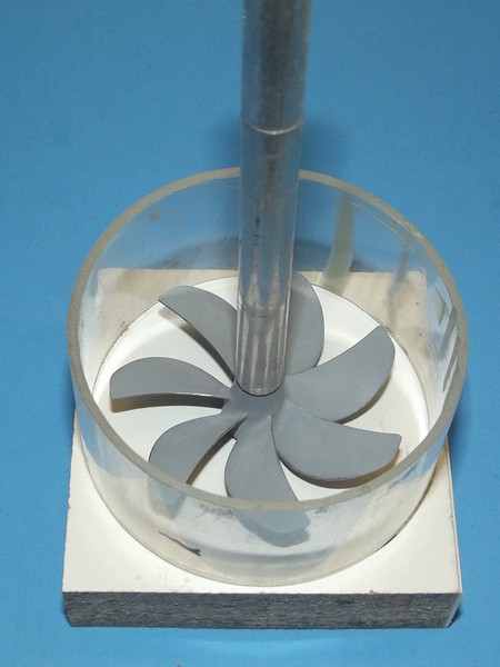
I needed to do something in between that is fun, such as designing and making of the propeller.
Although I must admit that this is also involving the profession of staring at pictures.
This will be my second propeller I made the first one was for my AKULA, there I used brass sheetmetal for the blades, now I wanted to add some body into it by designing the blades with actual airfoil shaped cross-sections.
I went all in (HWSNBN makes me do all this ****) I refer to HWSNBN excellent explanation of propeller making in a SCR from some time ago (damn I'm polite).
I do not want to post a picture of the prop assembly without explaining what it takes to design a propeller. If you want the skip all this just scroll down, but in my opinion, this is part of the fun.
The V3 I�m trying to make here is equipped with a tandem propeller. Each propeller has 4 blades, so the complete propeller assembly has 8 blades.
Based on the pictures I made following assumptions in my design.- It is a non-skewed propeller as the projected outline is symmetrical in most pictures (Projected Outline is the outline of the silhouette created on a screen just forward of the propeller, by a light directly behind the propeller, shining directly forward).
- The total propeller is quite short although it there are two propellers involved here, the propeller will have very little rake (A propeller with rake has blades that slant fore or aft of a line perpendicular to the propeller axis of rotation).
- The pitch of both propellers is the same (The pitch is the linear distance that a propeller would move in one revolution with no slippage).
- Pitch 53mm (17 feet for a real one)
- Diameter 49mm (6m for a real one)
- The projected area ratio is about 70% (Projected Area is expressed as a percentage of total disc area: PAR ≡ Projected Area/Disc Area, the Projected Area is the area enclosed by the projected outline of the blades and the disk area is the area of the circle scribed by the blade tips)
- It will be a constant pitch propeller (With Constant Pitch Propeller the propeller blades have the same value of pitch from root to tip).
- The cross-sections of the blade changes with the radius, the root is thicker than the blade tip (see expanded sections in picture below).
- Max blade thickness 2.5mm (root)
- Hub diameter, decided to make the whole hub assembly conical in continuation of the stern hull shape, the fwd end diameter of the fwd hub is 12mm, the aft end diameter of the aft hub is 10mm.
Pictures below are the propeller at different stage�s.
All blade roots milled to fit the slot in the propeller hub(s). I numbered the blades to make sure they go into the right slot.
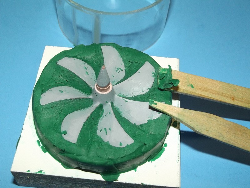
Blades were glued in the hub slots by means of thin CA, the root filled was accomplished by applying thick CA.
I coated everything with a shot of primer, which was sanded down, touched up all remaining imperfections. The sanding paper is used to clean up the mating surfases of the hubs.
I also provided recesses and bosses for indexing the different parts of the tandem propeller.
Second layer of primer applied��yeah, she is a beauty if I may say so myself.
Presented on the stern
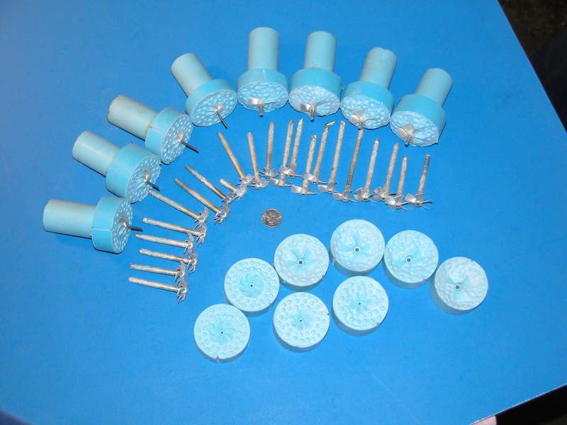
I still in doulbt if I should cast them in resin or white metal.......I don't own a spinning machine nor a melting tool......yet.
Grtz,
Bart
Practical wisdom is only to be learned in the school of experience.
"Samuel Smiles"Comment
-
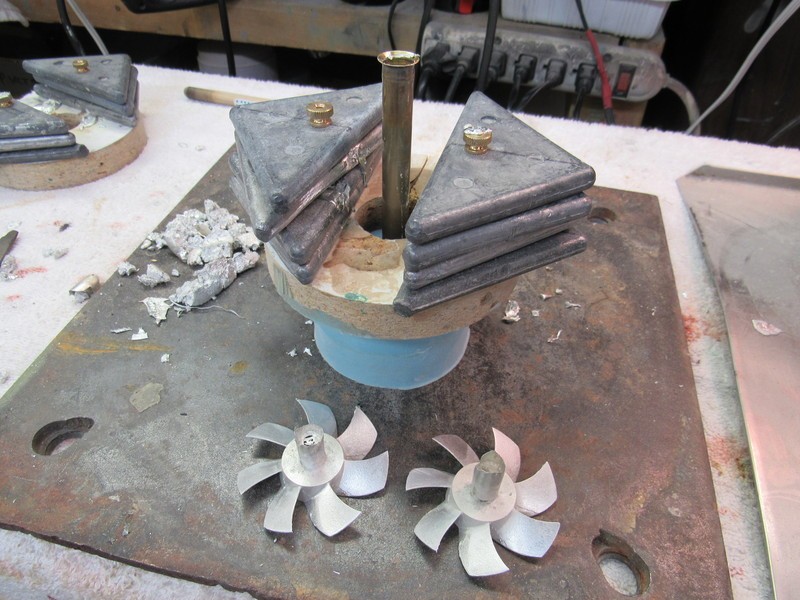
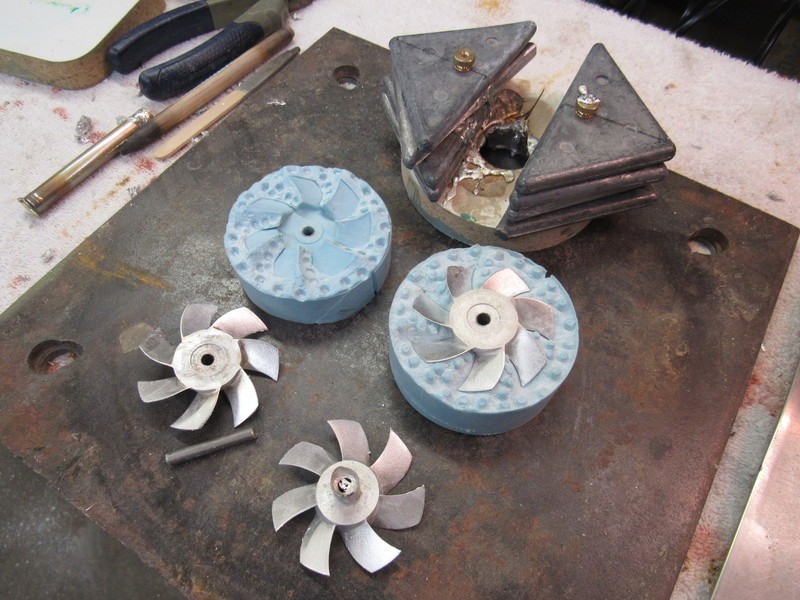
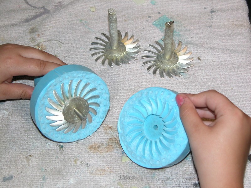
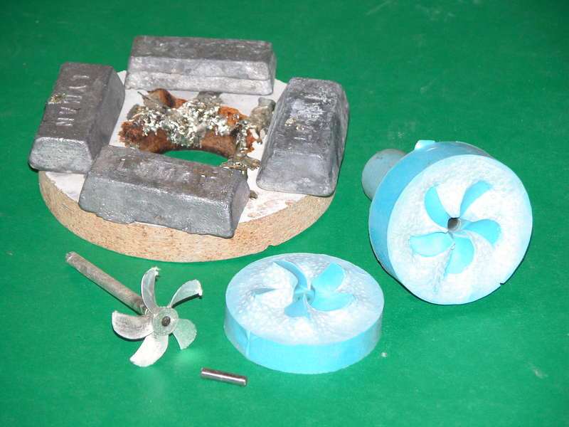
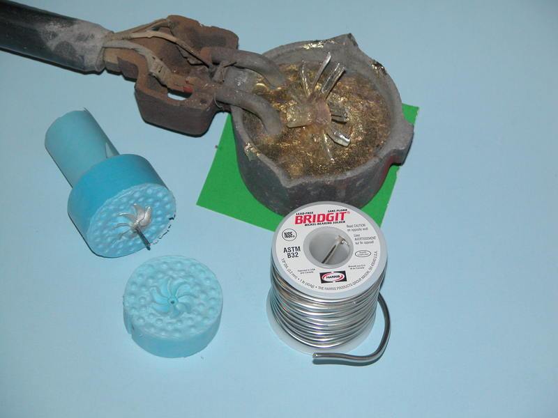
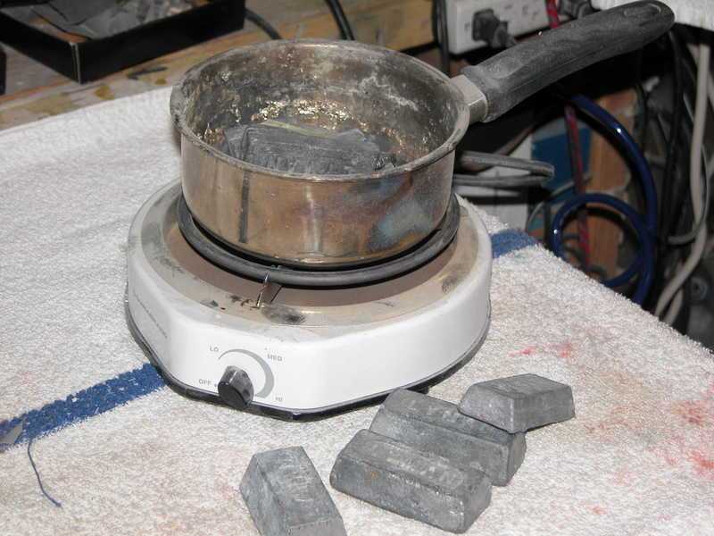
Wonderful work there, Bart. Cast them in white metal. A hot-plate and old pan is good enough to reach the 500-degrees needed to turn white-metal into a liquid. The silicon rubber used for most resin casting will tolerate this heat with little if any scorching

 Who is John Galt?
Comment
-
DavidWho is John Galt?Comment
-
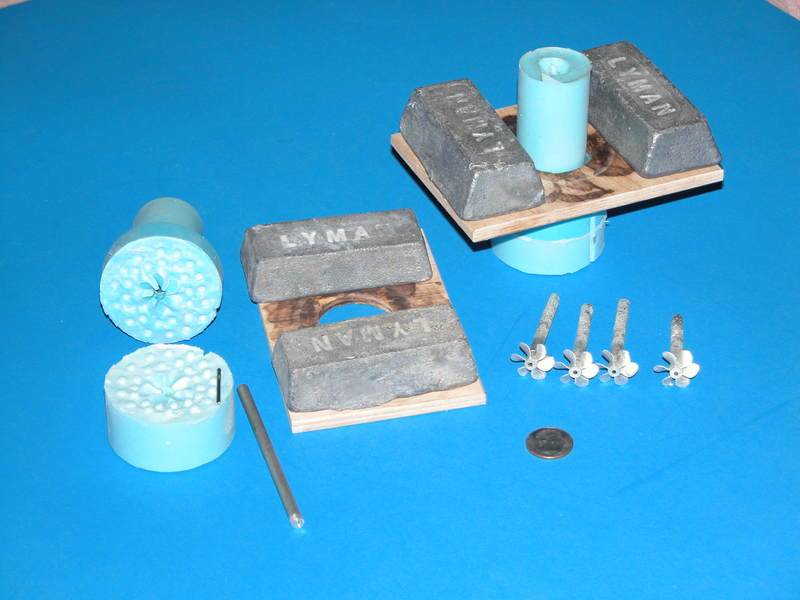
Ok thanks David that simplifies things.....you add quite some hydrostatic pressure with the sprue height so therefore I guess no need for risers as I don't see any in the pictures....air is pushed out the mould by the hydrostatic pressure of the white metal?
Grtz,
Bart
Practical wisdom is only to be learned in the school of experience.
"Samuel Smiles"Comment
-
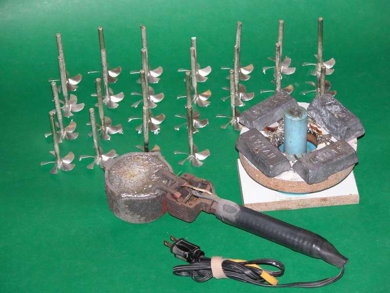
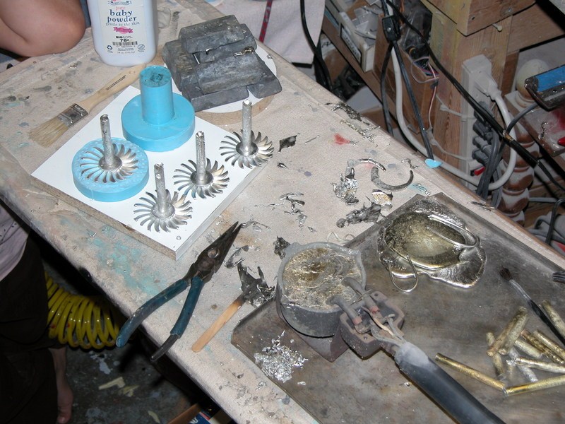
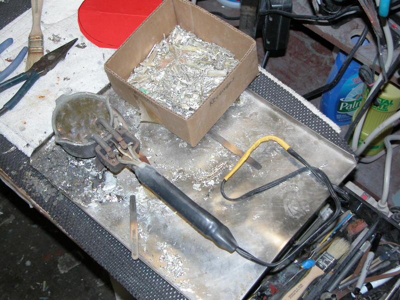
That's right, the pressure exerted at the bottom of the pressure-head is a function of the height of the fluid. Hydraulics 101. Lots of otherwise wasted sprue is recycled back into the pot once trimmed away from the cast propeller, no loss. Even the shavings from the lathe work goes back into the melting-pot.
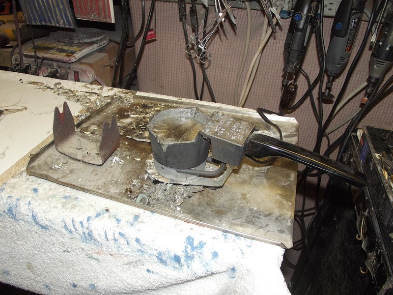
And you got it right about the displace air -- it squirts out between the tool flange faces as the metal is poured in. The elasticity of the rubber mold permits this.
DavidWho is John Galt?Comment
-
Hi Bart.Your propeller work looks very much correct. Great job!! / FredrikComment
-
Propellers and sail.
Seems that I�m completely into propellers this week.
Made a set for a 1/72 Gato for a member of the �pond staring community� and I made a high skewed 7 bladed prop for the V3.
The sub number I'm making has a tandem prop, but there are other sub numbers that have a high skewed one, now we can chose.
It took along time to get high skewed right, but I finally managed to tame the beast. Not all went right the first time. When I widened the hole for the propeller shaft to 3mm on the drill press. Afterwards I noted the bore was slightly out of center, bad news.
I rectified it on the lathe by first using a centre drill and then oversizing the bore of the hub to 4mm. Bushings are a mechanic best friend. Made a 4mm bushing with an inner bore of 3mm that fits perfect in the bore of the hub, problem solved.
Bushing in the making
Cleaning the faces of the hub
Primer sanded off
And ready she is
The sail, I was quite ****ed about the fact that after I applied the primer on the sail the details of the gratings / louvres were fainted. I expected some loss of detail but this was too much, I wanted those details to POP OUT.
I needed to remove the paint, after some test I found a thinner that didn�t dissolve the masking tape and still dissolved the paint itself. I used cotton sticks to apply the thinner, these are my go to for applying paint, CA�.I also use them as absorbers for excess glue and other stuff. Then I used the same to clean of the paint on top of the gratings/louvres. To remove the paint inside all those small recesses I used a toothbrush, I also have a collection of them fellows, always come in handy. Now all those details are back, and I�m happy.
Before, gratings/louvres partly filled with primer
Masking tape applied, tools used.
All done
Grtz,
Bart
Practical wisdom is only to be learned in the school of experience.
"Samuel Smiles"Comment
-
Why are the props printed with separate blades and boss rather than in one piece?Comment
-
I hate you!
DavidWho is John Galt?Comment
-
"Supports"
It will take a lot of supports if I want to print the prop in one piece.....and I hate supports, adding them and removing them.
By printing them separately I have more opportunities to angle the part in a way that I need the minimum on supports and preferable I want to place them on a flat surface which is easy to grind, sand, file or machine.
For me, it is more convenience to assemble the prop then to remove supports.
Grtz,
Bart
Practical wisdom is only to be learned in the school of experience.
"Samuel Smiles"Comment


Comment